¶ Chapter 7 — COMPLETE DENTURES
Reference Edition
This chapter is part of the Air Force Dental Laboratory Manual (2005) – Digitally Restored Edition.
This edition preserves the original publication while correcting OCR errors, restoring formatting, reconstructing damaged tables where necessary, and improving digital readability.
The technical content has not been rewritten, modernized, expanded, or altered.
It is provided as a professional reference. Modern instructional material is published separately throughout DentalTechnology.org.
¶ Section 7A — Overview
¶ 7.1. Introduction
A complete denture is a type of removable prosthesis designed to replace all of the natural teeth in an arch. The word “all” is used with reservation because a complete denture does not usually replace third molars and some situations require fewer teeth to be used. Patients sometimes need aset of complete dentures, one for each arch.
¶ 7.2. Steps in Complete Denture Construction
Complete dentures are fabricated by using a series of steps the dentist and laboratory technician perform as a team (paragraphs 7.2.1 through 7.2.18). Each step must be performed accurately and precisely. A slight error during any procedure can easily result in an unsatisfactory prosthodontic restoration. The major steps in complete denture construction are as follows:
7.2.1. The dentist makes preliminary impressions.
7.2.2. The technician pours diagnostic casts and fabricates custom trays.
7.2.3. The dentist makes final impressions.
7.2.4. The technician pours master casts.
7.2.5. The technician makes record bases with occlusion rims on the master casts.
7.2.6. The dentist uses the record bases with occlusion rims to determine the amount of facial muscle support the patient needs. The dentist then contours the occlusion rims to make a centric relation and occlusal vertical dimension jaw relationship record.
7.2.7. The technician uses a jaw relationship record to mount master casts in an articulator. A jaw relationship record, as received from the dentist, is a cast-mounting template.
7.2.8. The technician constructs a wax trial denture on the record bases, using the prescribed denture teeth.
7.2.9. The dentist checks the trial denture in the patient’s mouth for appearance and tooth contact relationships. The patient approves (or disapproves) the trial denture.
7.2.10. The technician makes all changes directed by the dentist.
7.2.11. After the patient and dentist approve the tr ial denture, the technician prepares it for investing. That is, the technician creates a uniformly thick palatal vault area and perfects the surface contours of the wax trial denture.
7.2.12. The technician creates a mold by flasking the wax dentures into denture flasks.
7.2.13. The technician removes the record base material and wax (boilout procedures) by heating and then separating the flasks and pouring boiling water over the cast to remove the wax.
7.2.14. The technician packs the molds with denture base resin and cures the resin.
7.2.15. The technician recovers cured dentures from the molds and remounts the dentures in the articulator to correct the occlusion.
7.2.16. The technician corrects processing errors (selective grinding)
7.2.17. The technician finishes and then polishes the dentures.
7.2.18. The dentist delivers the dentures to the patient.
¶ 7.3. Normal Denture Construction Procedures
The technician’s role is to pour impressions, trim casts, and finish dentures as part of normal denture construction procedures.
7.3.1. In complete dentures, an impression is an accurate, negative likeness of a highly specific intraoral area.
7.3.2. A cast is a positive likeness poured from an impression. When pouring an impression, there is a serious potential for omitting important impression features. After the gypsum product used to pour a cast sets, it is customary to trim the excess. It is very crucial to discriminate between cast areas that are excess and areas that are important to the success of the denture.
7.3.3. After processing the dentures in resin on the casts, finish and polish the dentures, using highly abrasive substances. During finishing, be extremely careful not to inadvertently changethe shape of a denture border. If this happens, it no longer corresponds to the original impression.
¶ 7.4. Relationships Between Impressions, Casts, and Dentures
Standard impression-cast-denture relationships are illustrated in Figures 7.1 and 7.2. For example, the buccal frenum of the mouth produces a buccal notch in the impression. When the impression is poured, a buccal frenum is visible on the cast. When the denture is made, the cast produces a buccal notch in the border of the denture.
¶ 7.5. Denture-Bearing Areas
7.5.1. In the maxillary arch, the denture-bearing areas are the residual ridge and hard palate. The border extensions of a maxillary complete denture are limited by the labial sulci, buccal sulci, pterygomaxillary notches, and vibrating line.
7.5.2. The denture-bearing areas of the mandible are the residual ridge, retromolar pads, and buccal shelves. The border extensions of a mandibular complete denture are determined by the labial sulci, buccal sulci, lingual sulcus, posterior extent of the retromylohyoid space, and posterior extent of the retromolar pads. NOTE: The negative and positive likenesses of these anatomical landmarks must be maintained throughout the impression-cast-denture-process.
¶ 7.6. Muscles Shaping Impression Borders
The muscles responsible for shaping impression borders (flanges) are listed in Figure 7.3.
¶ Section 7B — Functional Occlusions Organized for Complete Dentures
¶ 7.7. Complete Balance
7.7.1. According to the fourthedition of the Glossary of Prosthodontic Terms, complete balance is “the simultaneous contacting of the maxillary and mandibular teeth on the right and left in the posterior and anterior occlusal areas in centric and eccentric positions, developed to lessen or limit a tipping or rotating of the denture bases in relation to the supporting structures.” In simpler language, just about all of the teeth are supposed to be able to contact everywhere in centric occlusion and eccentric positions. In order to achieve this elusive ideal, dentures must be fabricated with a compensating curve (Figure 7.4)
Figure 7.1. Identification of Maxillary Arch Impressions, Casts, and Dentures.

7.7.2. A compensating curve is an alignment of occluding surfaces and incisal edges along definite anteroposterior and lateral curvatures for purposes of developing complete balance in dentures. The lateral component of the compensating curve is called the Curve of Wilson; the anteroposterior component is called the Curve of Spee.
7.7.3. In practice, the place where the compensating curve begins varies witheach dentist’s personal denture philosophy. It also varies with the kind of posterior denture tooth used. For example, the curve used with one manufacturer’s teeth starts in the first premolar region; a curve appropriate for a different tooth form begins in the first molar area. (When in doubt, read the directions.)
7.7.4. One major reason a compensating curve is necessary is the presence of the Christensen’s Phenomenon (Figure 7.5)
In this phenomenon, the condyles leave their fossae and move down the eminences until the incisors are edge to edge. If the compensating curve in a denture is shallow or absent, the descent of the condyles down the articular eminences shows up as a gap between the teeth posterior to the contacting incisors (Figure 7.5-B). The space is smallest anteriorly and becomes progressively greater posteriorly.
Figure 7.2. Identification of Mandibular Arch Impressions, Casts, and Dentures.

7.7.5. Recall that the occlusal plane of natural teethroughly conforms to the surface of asphere. Then why are balancing side and posterior protrusive contacts usually absent in the natural dentition? There are many possible reasons. Part of the answer might be the existing curvatures are not pronounced enough to overcome the Christensen’s phenomenon. Also, steep vertical overlaps between anterior teeth are very influential in causing separation of upper and lower posterior teeth, eventhough marked curvatures might be present. In Figure 7.5-C, enough of a compensating curve is present so most of the opposing teeth contact in protrusion.
¶ 7.8. Tooth Contact Characteristics of Completely Balanced Dentures
A completely balanced denture can be made using teeth with almost a ny cusp angle, from 0-degree through 33-degree teeth. However, most balanced complete dentures are made with cusped teeth.
7.8.1. Anterior Teeth. In centric occlusion there is about 1 mm of vertical and horizontal overlap between the maxillary and mandibular anterior teeth.
7.8.2. Working Side. The maxillary and mandibular anterior teeth on the working side contact each other. The posterior teethexhibit what is called cross tooth balance, which means the lingual inclines of the maxillary buccal cusps are in even contact with the buccal inclines of the mandibular buccal cusps and the lingual inclines of the maxillary lingual cusps are in even contact with the buccal inclines of the mandibular lingual cusps.
Figure 7.3. Muscles Responsible for Shaping Impression Borders.

Figure 7.4. Compensating Curve.

7.8.3. Balancing Side. The buccal inclines of the maxillary lingual cusps are in even contact with the lingual inclines of the mandibular buccal cusps, and there is no contact between upper and lower anteriors.
Figure 7.5. Christensen’s Phenomenon.

7.8.4. Protrusive. When the incisors are edge to edge, the posteriors contact just short of a cusp tip to cusp tip relationship.
¶ 7.9. Advantages of Completely Balanced Dentures
7.9.1. Cusped teeth look more natural than 0-degree teeth.
7.9.2. Cusped teeth seem to break up food better than nonanatomic teeth.
7.9.3. Balanced dentures are somewhat resistant to tipping forces. (When a denture “tips,” one end pops up while the other stays down.)
¶ 7.10. Disadvantages of Completely Balanced Dentures
7.10.1. Balanced dentures are more difficult to set.
7.10.2. Completely balanced dentures work well for patients with good ridges, but are not as effective for patients with poor ridges. Cusped teeth set for balance are expected to mesh well in centric occlusion. If a patient’s residual ridge height is insufficient to support a balanced denture, lateral mandibular movement will cause the lowe r denture to dislodge and stay behind or the upper denture to lose its seal and travel with the laterally moving lower denture.
7.10.3. Precise records are required to accurately reproduce the mandible’s movements on the articulator. This involves a more careful and time-consuming technique.
7.10.4. With balanced dentures and cusped teeth, there is an increase in lateral forces which can be detrimental to the residual ridges.
¶ 7.11. Nonbalanced Dentures
The only position in which tooth contact s are deliberately organized is in centric occlusion. Once the dentures leave centric occlusion, any contacts that develop in working, balancing, and protrusive excursions are present by chance. The contacts have not been intentionally programmed into the denture setup. This type of setup is primarily used when asingle denture opposes natural dentition or a partially edentulous arch.
¶ 7.12. Using Cusped Teeth
In this type of setup, 20-degree (or less) posterior teeth are set along a modest compensating curve in the tightest centric occlusion possible. If an Angle’s Class I molar relationship is indicated, there will probably be 1 mm of horizontal and vertical overlap between maxillary and mandibular anterior teeth. Little attention is paid to interferences that might arise in lateral excursions. The questionable value of the setup lies in the fact that, although it is easily and quickly done, these dentures tend to tip and slide in contact positions other than centric occlusion.
¶ 7.13. Monoplane Denture Setups Using 0-Degree or Nonanatomic Teeth
In this denture occlusion, 0-degree teeth (no cusps) are set on a flat plane (no compensating curve).
¶ 7.14. Tooth Contact Characteristics of Nonbalanced Dentures
7.14.1. Anterior Teeth. In centric occlusion, anterior teeth normally have a vertical overlap of 0.0 mm and 1 to 2 mm of horizontal overlap.
7.14.2. Working Side. There are isolated, unprogrammed contacts among a few upper and lower teeth on the working side.
7.14.3. Balancing Side. On the balancing side, there is us ually no contact between any of the upper and lower teeth.
7.14.4. Protrusive. When the incisors are edge to edge, there is no contact posteriorly.
¶ 7.15. Advantages of Monoplane Dentures
7.15.1. Monoplane dentures are somewhat easier to set than completely balanced dentures.
7.15.2. A set of monoplane dentures function well in almost all patients and is the denture occlusion of choice for patients with poor ridges. A set of monoplane dentures minimizes lateral stresses on the residual ridge. Due to the absence of inclined planes, the ridges are subject to vertical pressures which are considered less damaging.
7.15.3. The monoplane principle is the denture occlusion of choice for Class II and Class III jaw relationships. It is also the denture occlusion of choice for crossbite cases.
¶ 7.16. Disadvantages of Monoplane Dentures
7.16.1. The 0-degree teeth don’t look as natural as cusped teeth.
7.16.2. The 0-degree teeth might not break up food as well as cusped teeth.
7.16.3. Monoplane dentures have more of a tendency to tip than balanced complete dentures. In fact, the lack of protrusive balance is a special invitation to tipping.
¶ 7.17. Lingualized Occlusion
This denture occlusion is very versatile and can use either the balanced or nonbalanced concept. Lingualized occlusion uses cusped maxillary posterior teeth set against 0-degree or shallow cusp mandibular posterior teeth. The maxillary lingual cusps acts as the major functioning cusp occluding onto the mandibular teeth.
¶ 7.18. Tooth Contact Characteristics of Lingualized Occlusion
7.18.1. Anterior Teeth. In centric occlusion, the anterior teeth have a vertical overlap of 1 mm and a horizontal overlap of 1 mm.
7.18.2. Working Side. The maxillary and mandibular anterior teeth on the working side contact each other. In the posterior, only the lingual inclines of the maxillary lingual cusps are in even contact with the buccal inclines of the mandibular lingual cusps.
7.18.3. Balancing Side. On the balancing side, there is no contact between any of the maxillary and mandibular teeth in a nonbalanced setup. In a balanced setup, the buccal inclines of the maxillary lingual cusp contact the lingual cusp of the mandibular buccal cusp.
7.18.4. Protrusive. When the incisors are edge to edge, posterior contact is possible provided the Curve of Spee is properly formed.
¶ 7.19. Advantages of Lingualized Occlusion
7.19.1. There is maximized cutting efficiency with minimized lateral forces (denture base slide)
7.19.2. There are improved esthetics over purely 0-degree posterior teeth arrangements.
7.19.3. Maxillary cusp teeth break up food better.
7.19.4. Lingualized occlusion has a limited amount of lateral forces due to the small area of contact between the maxillary lingual cusp and the 0-degree mandibular teeth during lateral excursions.
7.19.5. This occlusion can be used for a wide variety of residual ridge conditions.
¶ 7.20. Disadvantages of Lingualized Occlusion
Lingualized occlusion is a compromise between using anatomic and nonanatomic posterior tooth forms. In a nonbalanced setup, the dentures may stilll tip in contact positions other than centric occlusion due to the lack of balancing contacts.
¶ Section 7C — General Rules for Pouring, Trimming, and Handling Casts
¶ 7.21. Impression Considerations To Obtain an Accurate Cast
7.21.1. Always follow infection control guidelines when pouring and trimming a cast. (For information, refer to Chapter 1, Section 1D.)
7.21.2. Pour the impressions as soon as possible. Keep in mind that alginate impressions should be poured within 10 to 15 minutes after removal from the mouth and all impression materials are subject to distortion.
7.21.3. Remove the mucous film and debris from the surface of the impression with a gentle stream of body temperature water. Some manufacturers suggest “fixing” hydrocolloid impression materials before pouring. An impression made from agar may require fixing by immersing it into a 2 percent solution of potassium sulfate for 5 minutes. This fixing improves the surface detail and hardness of the cast. Most agar products now contain potassium sulfate (an accelerator for the gypsum setting reaction), and soaking is no longer required.
¶ 7.22. Pouring Casts
7.22.1. Carefully follow the manufacturer’s directions when preparing a mix of gypsum product. The water-to-powder ratio is absolutely critical. Because gypsum products are easily contaminated by moisture, preweigh them into convenient amounts and store them in airtight containers. Alternatively, purchase preproportioned, sealed packets of gypsum.
7.22.2. Use a proper separator, such as super sep, when pouring one gypsum material against another.
7.22.3. Remember, the primary objective when pouring a cast is to capture all surface detail of the impression in as bubble-free a manner as possible. Use a vibrating table to make a thick, gypsum mix flow into all of the crevices of the impression (Figure 7.6). The usual practice is to pour a small amount of the gypsum product into a corner of the impression and let it slowly advance to the other side.
Figure 7.6. Pouring a Typical Impression.

7.22.4. After covering the entire surface of the impression, progressively larger amounts of the mix may safely be added. There is a rate of vibration that is best for the characteristics of each mix of gypsum and type of impression material. The vibration intensity should be set high enough to make the material move across the surface of the impression. The vibrator is set too high if the impression “jum ps” in your hand, if the mix moves sofast it skips over surface detail, or if vibration wave patterns develop on the surface of the mix which can cause entrapment of air.
¶ 7.23. Separating, Trimming, and Storing Casts
7.23.1. Separate a cast from an impression after the heat generated by the final setting reaction dissipates completely (about 45 minutes after pouring). If a cast is not separated from an alginate impression before the alginate shows signs of dehydration, the cast will probably show unacceptable surface dam age. Do not allow a poured cast to stand in an alginate impression for more than 1 hour.
7.23.2. For a modeling plastic impression (commonly called compound), uniformly heat the material in a water bath (140 oF) until it softens before attempting to separate the cast from the impression.
7.23.3. Do not trim a cast for at least 2 hours after it has reached the final set.
7.23.4. Rinsethe cast in a container of saturated calcium sulfate dihydrate solution (SDS) trimming procedure. Never trim a dry cast on a wet model trimmer because the slushy debris coming off the trimming wheel falls on the dry surface and becomes permanently attached to the cast surface. Use only SDS for soaking or rinsing casts.
7.23.5. Make sure the cast includes all of the denture support areas and features that define denture borders. Keep the cast free of nodules or voids. When trimming a maxillary cast, follow the general shape shown in Figure 7.7. Cut mandibular cast to correspond with the shape shown in the same figure. Fully represent the sulci areas in the cast, but not more than 3 mm deep. The sulci are routinely protected by a peripheral “land” area or ledge extending 4 mm outward.
7.23.6. Make sure the cast extends 5 mm beyond the ptyerygomaxillary notch areas of the maxillary arch and 5 mm beyond the retromolar pads of the mandibular arch. A cast should be about 15 mm (5/8 inch) thick at its thinnest area (usually the palatal vault of the upper and the tongue space region of the lower)
7.23.7. Store the cast in a safe place to prevent damage.
Figure 7.7. Trimming Maxillary and Mandibular Casts.

¶ 7.24. Preliminary Impressions
7.24.1. Impressions are made by carrying a suitable impression material to the mouth of the patient in a specially shaped container (impression tray). There are two basic kinds of impression trays; prefabricated and custom.
7.24.2. Prefabricated trays are available in a range of types, shapes, and sizes.
Figure 7.8 contains two types--maxillary rimlock (on the left) and maxillary edentulous (on the right). All preliminary impressions are made in prefabricated trays. Technicians make custom trays on preexisting casts. Dentists make preliminary impressions as a first step in many prosthodontic treatment plans. Because casts made from these impressions (diagnostic casts) are used to evaluate the patient’s dental problems (diagnosis) as well as to make custom trays, these casts must be made as accurately as master casts.
7.24.3. Alginate is the material used to make preliminary impressions. Alginate impressions brought into the laboratory should be poured immediately after disinfection is completed. Alginate impressions begin to distort within 10 to 15 minutes after the material is removed from the patient’s mouth. Placing the impression in a 100 pe rcent humid atmosphere (humidor) may retard the distortion. Even if a hum idor is available, an alginate impression should be poured within 10 minutes after it is made.
¶ 7.25. Two-Step Method of Pouring a Diagnostic Cast
7.25.1. To help prevent distortion caused by pressure from its own weight, a poured impression may be suspended by the handle from a tray holder (Figure 7.9). In a two-step method, pour the anatomic portion first; then add the base as a second step (Figure 7.10)
Figure 7.8. Two Types of Prefabricated Trays.

Figure 7.9. Tray Holder.

7.25.2. For the first step, fill the anatomical portion of the impression as described above, to include full-border coverage. To guarantee a union between the two pours, leave nodules and roughened peaks on the surface of the first pour. After the final set, wet the first pour with SDS and invert it into a newly mixed mound of the same material. While it is stilll soft, shape the mound to the desired size and thickness. This second step forms a base. Build up a basethickness of about 18 mm (1/4 inch). Overbuild the base to com pensate for trimming reductions. Separate and trim the cast as previously directed.
Figure 7.10. Two-Step Method of Pouring a Cast.

Cast separated from the impression
Cast trimmed
7.25.3. In a mandibular impression, the second pour tends to creep up over the lingual flanges and lock the tray into the hardened mix. A tray is difficult to remove under these conditions, and the cast may be ruined in the process. To prevent this problem, invert the first pour onto the second mix of material without letting the tray become buried. While the material is stilll soft, flatten and shape the tongue area of a mandibular impression so the area is relatively smooth and is about 1 mm above (occlusal to) the lingual sulcus.
¶ 7.26. One-Step Method of Pouring a Diagnostic Cast
There are quicker ways of pouring diagnostic casts than the two-step method as follows:
7.26.1. Impressions must never be poured, then inverted into a mound of gypsum material to form the entire cast in one step. The material tends to settle toward the base while it is setting, leaving the softer material toward the anatomic areas of the cast, producing a marginally adequate cast. The gypsum mix has a tendency to fall away from important impression borders, and the potential for soft cast surfaces can be greater. In addition, it is difficult to control the thickness of the base and the orientation of the anatomic portion to the base.
7.26.2. An impression may be filled with a mix of gypsum product with enough material stacked up for a base right on top (sometimes called the “upright method”). This technique is more successful with maxillary than with mandibular impressions.
7.26.3. Some dentists request a “high mount” pour of the diagnostic cast. In this method, the impression is poured similar to the upright method, making sure the first pour is at least 15 mm thick in the dentulous areas and 10 mm thick over edentulous areas. Large retention nodules are placed, but no attem pt is made to develop a base. After final set and separation of the cast, the retention nodules are flattened slightly. This method is usually used when the dentist will be using the casts to make a diagnostic mounting and will have no need to remove the casts from the mountings.
7.26.4. In general, though, it is best to depend on the two-step method. It will save time in the long run by ensuring the best cast quality.
¶ Section 7D — Custom Trays
¶ 7.27. Overview
7.27.1. Prefabricated trays are made to fit everyone moderately well, but thesetrays fit no one perfectly. On the other hand, a custom tray provides an impression material carrier which helps the dentist make a more accurate impression than he or she could make by using a stock (prefabricated) tray.
7.27.2. The custom tray is made on a diagnostic cast. The dentist draws the border outlines of the proposed custom tray on the diagnostic cast and gives other design directions (such as handle position, amount and placement of wax spacer if required, and the need for vertical stops). The tray is then made to conform to the design.
7.27.3. Some of the more popular ways of making custom trays are the self-curing resin dough method (paragraph 7.28), vacuummethod (paragraph 7.29), and light cured material method (paragraph 7.30)
¶ 7.28. Self-Curing Resin Dough Method
This is a bulk method for using resin as opposed to “sprinkle on” methods.
7.28.1. Preparing the Cast. First, use baseplate wax to generously fill in all undercuts within the tray area outlined on the cast (Figure 7.11-B). Next paint the cast with two layers of tinfoil substitute to prevent the acrylic resin from sticking.
7.28.2. Molding the Dough. Use a simple stone mold to control the shape and thickness of the resin dough (Figure 7.12). This preshaped resin mass results in a tray of consistent quality when adapted to the cast. Once made, the mold may be used indefinitely. Making a mold is a simple procedure following the steps as outlined below:
7.28.2.1. Using two sheets of athletic mouthguard material, cut one sheet the shape of a maxillary arch to include the palate. Cut the other sheet the shape of a mandibular arch not including the tongue space.
7.28.2.2. Place each of the sheets of athletic mouthguard on aslab and pour gypsum 15 mm (5/8 inch) thick over the material to include the edges.
7.28.2.3. Remove the mouthguard material after the stone mix sets and lightly petroleum the recesses.
7.28.2.4. Cut a 6-inch length of 1 -inch diameter dowel to use as a roller.
7.28.3. Fabricating the Tray.
7.28.3.1. Mix the monomer and polymer components of the autopolymerizing resin. Always follow the manufacturer’s monomer-polymer proportioning directions. Allow the mix to set until it reaches a dough-like consistency.
7.28.3.2. Always wear gloves when handling acrylic resin. Lightly coat the glove fingers with petrolatum before handling the dough. Also ensure that the mold is coated with petrolatum. When resin becomes doughy, remove from mixing container and quickly knead the dough to ensure thorough mixing of the polymer and monomer. Place the resin into the stone mold. Cover the resin with a polyethylene sheet, and then roll out the resin to match the mold’s shape and thickness (Figure 7.11-C).
Figure 7.11. Fabricating a Maxillary Custom Tray (Autopolymerizing Resin).

7.28.3.3. Trim away any excess dough and lift the acr ylic resin blank from the mold. Store excess acrylic in a jar to use later for fabricating a tray handle.
7.28.3.4. Center the resin over the cast and rapidly adapt the dough to the cast’s surfaces (Figure 7.11-D)
Be careful not to create thin s pots by pressing too hard. Shape the resin to the borders and cut away the excess with a sharp knife.
7.28.3.5. Attach a handle to the tray (Figure 7.11-E)
Ensure the handle is strong enough to withstand considerable force and its shape does not interfere with lip movements. If you work fast enough, you should be able to usethe unpolymerized excess from the first mix for the handle. If not, mix another small amount of tray resin. When polymerization reaches the dough stage, form it into an “L.” Use a few drops of monomer to moisten the attachment site between
the handle and the tray. Press the base of monomer should provide good bonding.
the handle onto the moistened area. The fluid
Figure 7.12. Baseplate Mold for Autopolymerizing Resin Material.

7.28.4. Finishing the Tray. After the acrylic resin has set, remove the tray from the cast. The posterior border of a maxillary custom tray is supposed to extend a short distance onto the soft palate. Mandibular custom trays cover the retromolar pads. Trim the tray’s flanges back to the dentist’s peripheral border markings. Use an ar bor band to remove bulk. Use acrylic finishing stones and burs for finer details. Make sure there are no sharp edges on the tray’s borders. NOTE: Making custom trays from autopolymerizing resin dough gives excellent results. Made this way, the trays are rigid and dimensionally stable. Most of the time, this is the preferred method.
¶ 7.29. Vacuum Method
The vacuummethod (Figure 7.13) is a viable alternative to the autopolymerizing resin dough method.
7.29.1. Equipment and Materials. For this procedure, use a unit capable of vacuum-forming a plastic sheet (thermoplastic vinyl resin). (The commercially available OMNIVAC ® unit falls in this category.) Plastic sheets come preformed to fit the machine and in color-coded thicknesses appropriate for different purposes. Custom trays are made from extra weight (0.125 inch) tray material.
7.29.2. Cast Preparation. For a handle, cut ascrap piece of tray material 1-inch long and 1/2-inch wide and round off the corners on one end. Attach the square end to the cast surface with sticky wax. Place it on the anterior residual ridge in the midline and stand it upperpendicular to the cast (Figure 7.13-B). Thoroughly wet the cast with SDS. Block out all undercuts with wet tissue.
7.29.3. Tray Formation. Place a sheet of tray material in the sliding carriage of the OMNIVAC and raisethe carriage completely. Switch on the heating element and position it directly over the tray material. Place the cast on the vacuum base. When the plastic sheet sags about 1 inch, turn on the vacuumm otor. Lower the sliding carriage and bring the tray material down over the cast
(Figure 7.13-C). Swing the heating element aside. Position the impression tray handle at an angle that is 45 degrees to the base of the cast. Turn off the heating element. When the tray material is cool, turn off the vacuummotor.
7.29.4. Tray Finishing. Draw a line on the tray material indicating the outer edge of the cast’s land area (Figure 7.13-D). Use a separating disc to follow the line and cut through the plastic to the cast (Figure 7.13-E). After completing the cut, separate the tray and the cast from the excess. Lift the tray off the cast. For mandibular trays, usethe separating disc to cut away the bulk of the tongue space. ALWAYS WEAR SAFETY GLASSES WHEN USING A SEPARATING DISC. Use an arbor band to trim the border of the tray down to the design. Use an acrylic finishing stone to round the edges. Clean away any remaining tissue or sticky wax.
Figure 7.13. Custom Tray Fabrication by the Vacuum Method.

¶ 7.30. Light-Cured Material Method
Light-cured materials are becoming popular because of their ease of use and quickness in making a tray.
7.30.1. A light curing unit is needed to thoroughly cure the material. Materials come prepackaged for consistent size and thickness. The Dentsply International ® Triad system is a complete lightcured system for making custom trays.
7.30.2. Block out cast undercuts with wax or molding compound. Then apply a separator to the cast.
7.30.3. Adapt the tray material to the cast, being careful not to create any thin areas. Once the tray material is removed from the manufacturer’s package, the working time of the material begins. Light in the working area will start the curing process. Position the wire support for the handle in the uncured tray (Figure 7.14-A). Add the material around the wire support to form a tray handle (Figure 7.14-B).
7.30.4. Cure the tray in a light-curing unit for two minutes (Figure 7.14-C)
Remove the tray from the cast and apply the manufacturer’s air barrier coating on all sides. Cure the tray for an additional 8 minutes.
7.30.5. Finish the tray to the design line with carbide burs, ensuring the peripheral border is smooth and has no sharp edges (Figure 7.14-D)
The tray may also be perforated to help retain the impression material.
Figure 7.14. Custom Tray Fabrication by the Light-Cured Method.

¶ 7.31. Custom Tray Spacer Modifications
In the preceding technique descriptions (paragraphs 7.28 through 7.30), the trays were closely adapted to the diagnostic cast. However, more often than not, the dentist prefers a tray that provides room for controlled thickness of impression material (Figure 7.15). Spacers used to develop tissue stops accomplish this purpose. The stops are made to hold the tray off the cast by a distance equal to the thickness of the spacer. When the spacer is removed and the tray is placed in the patient’s mouth, the stops hold the inner surface of the tray out of contact with the patient’s tissue. The space between the tray and the tissue is filled with a very accurate, relatively fluid impression material called a wash (such as zinc oxide and eugenol paste) or rubber base.
7.31.1. Self-Curing Resin Trays.
7.31.1.1. Adapt a layer of baseplate wax to the blockout design line on the diagnostic cast after you fill in the undercuts. If prescribed, cut out four small pieces of the baseplate wax over the crest of the ridge at areas outlined in the molar and canine regions.
7.31.1.2. Apply a tinfoil substitute to the gypsum surfaces of the cast to prevent the acrylic resin from sticking. Apply a thin layer of petroleum to the surface of the baseplate wax to make removing the wax from the polymerized tray easier. Use the self-curing dough method to make the tray.
Figure 7.15. Custom Tray Wax Spacer.

Wax spacer incompleted tray

Wax spacer adapted to tray design
7.31.1.3. After the resin is hard, remove the tray from the cast and pull the baseplate wax off the tissue surface of the tray. Some dentists may require the blockout wax to remain in the tray until the final impression is taken. If tissue stops are used, they should appear on the ridge areas where the four pieces of baseplate wax were originally cut out. Trimany excess acrylic resin to the outline border on the cast. Round and smooth the borders of the tray.
7.31.1.4. Be sure to clean away all traces of petrolatum that might be present on the tissue surface of the tray. Shellblasting does this very effectively.
7.31.2. Vacuum-Formed Trays.
7.31.2.1. As described in paragraph 7.29.2, use sticky wax to attach the handle to the dry cast. Fill in the undercuts with wet tissue or some other heat-resistant substitute. Adapt one or two layers of wet tissue (about 2 mm thick) to the cast surfaces, including the peripheries. If prescribed, cut four tissue stops through the tissue layer (down to the cast) and place the stops in the second molar and canine regions.
7.31.2.2. Operate the OMNIVAC or similar unit. As soon as the carriage is dropped, use a blunt instrument to adapt the tray material into the tissue stops. Cut away the excess tray material, remove the tray from the cast, and trim it topredetermined borders.
7.31.3. Light-Cured Tray Method.
7.31.3.1. Adapt a layer of baseplate wax to the blockout design line on the diagnostic cast after you fill in the undercuts. If prescribed, cut out four small pieces of the baseplate wax over the crest of the ridge at areas outlined in the molar and canine regions. Adapt the tray material to the cast. Position wire support for handle then cure tray for 30 to 45 seconds to “set” the material.
7.31.3.2. Separate the tray and remove wax spacer. This will prevent melting the wax in the curing unit. Add material for the handle and cure tray for 2 minutes. Apply the manufacturer’s air barrier coating and cure tray for an additional 8 minutes. Finish the tray to the design line.
¶ Section 7E — Master Casts
¶ 7.32. Overview
The dentist uses the custom tray to make a final impression of the patient. In most cases, final, complete denture impressions are boxed before pouring the master cast. Boxing the impression represents a way of confining the flow of the stone to control the shape, thickness, and density of the cast. This is the best method to make sure that all peripheral borders are complete. There are several ways to box an impression. The method selected depends on the kind of wash material the dentist used. (See paragraphs 7.33 and 7.34.)
¶ 7.33. Wax Bead, Box, and Pour System
This method (Figure 7.16) can be used with all final impression materials, but is particularly suited for elastic materials such as zinc oxide and eugenol paste or impression plaster.
Figure 7.16. Wax Bead, Box, and Pour System.

Maxillary arch impression beaded

Impression boxed
7.33.1. Maxillary Impression.
7.33.1.1. Carefully adapt a strip of utility wax around the impression (3 mm from the edges of the flanges.) Extend the wax strip across the posterior border, about 6 mm behind the vibrating line. Make the beading on one side continuous with the beading on the other. Lute (seal) the wax to the tray with a hot spatula. To avoid possible damage to the impression, seal the beading to the tray from the side opposite the flange edges.
7.33.1.2. Build asidewall around the circumference of the beading to provide an enclosure or “box” into which artificial stone can be poured. Make the sidewall of boxing wax or baseplate wax cut wide enough to extend 15 mm (5/8 inch) above the highest point on the impression. Just as you sealed the beading to the tray from the side opposite the flange edges, do the same when you lute the boxing material to the beading. Water test the assembly for leaks by filling the impression with water. The maxillary final impression is now boxed and ready for pouring.
7.33.2. Mandibular Impression.
7.33.2.1. Box the mandibular impression the same way you boxed the maxillary impression. EXCEPTIONS: From the distal 1/3 of the buccal flange, across the posterior border of the retromolar fossa, and down to the retromylohyoid eminence on each heel, usetwo thicknesses of utility wax to provide an adequate land area on the resultant cast.
7.33.2.2. Continue the beading wax around the outline of the lingual area 3 mm distant from the edges of the lingual flanges. Fill in the lingual area with baseplate wax luted to the beading. After the impression is boxed, test it for leaks and pour the cast.
¶ 7.34. Plaster-Pumice Matrix, Box, and Pour System
7.34.1. Overview. The small amount of force used to mold boxing material around a utility wax bead sometimes alters the shape of a final impression made with an elastic impression material. The plaster-pumice matrix, box, and pour system is appropriate for boxing any kind offinal impression, but is particularly suited when using an elastic impression material. The matrix is composed of equal volumes of plaster and coarse pumice. Pumice is incorporated into the plaster to weaken the matrix and make separation of the poured cast easier. It is this matrix that supports the tray and edges of a final impression made with an elastic impression material of rubber base, silicone, etc.
7.34.2. Maxillary Impression.
7.34.2.1. With a small piece of clay, support the tray about 12 mm (1/2 inch) off the surface of the table. Take the tray with the attached clay and put it aside. Stack aslushy, yet cohesive, mound of the 50/50 plaster pumice mix on a flat, nonabsorbent surface. Make the patty about 12 mm larger than the diameter of the impression. Place the impression and clay stop into the patty tissue side up.
7.34.2.2. Manipulate the matrix mix so 1.5 mm of flange height is visible all the way around, exposing at least 6 mm of the impression’s surface posterior to the vibrating line. Ensure enough of the matrix mix remains around the circumference of the impression to create a ledge at least 8 mm wide.
7.34.2.3. Let the matrix achieve initial set. Hold a razor-sharp blade at right angles to the flanges and carefully (and uniformly) cut to e xpose 3 mm of the flanges. After the matrix reaches final set, trim a 6 mm land area around the circumference with a cast trimmer.
7.34.2.4. Paint the land area with two coats of a suitable stone to stone separator such as Super Sep®. Wrap the matrix with boxing wax that stands 15 mm (5/8 inch) above the impression’s highest point and lute the wax to the matrix. Water test the boxed impression for leaks and pour the cast.
7.34.3. Mandibular Impression.
7.34.3.1. Box the mandibular impression the same as the maxillary impression. EXCEPTIONS: Usetwo pieces of clay—one on the right and the other on the left in the first molar areas—to hold the tray (especially the heels) 12 mm (1/2 inch) off the table (Figure 7.17).
7.34.3.2. Before the matrix reaches its initial set, try to create asmoothly contoured tongue space. Complete the contouring of the tongue space with a sharp knife after the final set. Make a 6 mm wide land area. Extend it from the distal 1/3 of the buccal flange, across the posterior border of the retromolar fossa, and down to the retromylohyoid eminence on each heel. Paint two to three coats of separator onto the land and tongue space regions.
Figure 7.17. Plaster-Pumice Matrix, Box, and Pour System.

¶ 7.35. Pouring Master Casts
7.35.1. Most final impression materials do not require a coating of separator before a cast is poured. However, impression plaster is the exception. Pouring a cast against impression plaster without the use of an intervening separator causes the impression and the stone to bond together.
7.35.2. Before pouring a cast, proportion the water and gypsum according to the manufacturer’s directions. Spatulate the mixture thoroughly to obtain a homogeneous mix. To obtain a dense, accurate cast, always vacuum spatulate stone for final impressions. Place a small quantity of the mix in the boxed impression on the vibrator and make it flow around the impression. Continue to add small quantities of stone until the tissue surface of the impression is covered; somewhat more rapidly, fill the boxing to the desired level.
¶ 7.36. Separating and Trimming Master Casts
7.36.1. After the stone has final set (according to the manufacturer’s directions), remove the boxing materials. If a plaster-pumice matrix was used, the matrix should break away cleanly and easily.
7.36.2. Some dentists make their own modeling plastic trays at chairside to carry corrective wash materials. Others use modeling plastic to form the borders of custom resin trays before they make a final impression. If modeling compound was used in the final impression procedure, place the
assembly in 140 oF water for 3 minutes so it will separate. After separating a cast from any kind of impression, always inspect the cast’s surface for inaccuracies (irregular voids and positive and negative bubbles).
7.36.3. Casts poured from properly boxed impressions require minimal trimming. Dip the cast in SDS, usethe cast trimmer to flatten the base (15 mm thick), and produce land areas of proper dimensions as discussed in paragraphs 7.23.4 and 7.23.5. Rinsethe debris from the cast with SDS.
7.36.4. Let the cast dry somewhat and cut indexing grooves into the base of the cast. These grooves can assume different lengths and cross-sectional shapes, depending on the wishes of the dentist. Two styles are shown in Figure 7.18. Do not cut indexing grooves so deeply they compromisethe strength of the cast.
Figure 7.18. Indexing Grooves.

¶ Section 7F — Record Bases With Occlusion Rims
¶ 7.37. Characteristics
Record bases with occlusion rims (Figure 7.19) are a combination of a base material that accurately fits the cast (record base) and an arch-shaped wax buildup (occlusion rim) that occupies the space formerly occupied by the patient’s natural teeth.
¶ 7.38. Primary Uses
Primary uses for record bases with occlusion rims (paragraphs 7.38.1 through 7.38.6) are to:
7.38.1. Help the dentist select and properly position denture teeth. The dentist shapes and positions the labial surfaces of the occlusion rims to approximate the amount of lip support required by the patient. The dentist then adjusts the vertical length of the maxillary occlusion rim to indicate the length of the incisor teeth. Some dentists scribe marks on the occlusion rims as aids in choosing and positioning denture teeth (Figure 7.20). The markings are usually made on the maxillary occlusion rim, but they occasionally carry over onto the mandibular rim.
7.38.1.1. Midline Marking. The midline marking represents the center of the patient’s face. The incisive papilla is also a good guide.
Figure 7.19. Record Base With Occlusion Rim.

Figure 7.20. Occlusion Rim Markings.

7.38.1.2. High Lip Line. Some dentists mark the high lip line on the maxillary rim. This line indicates the level to which the upper lip rises when the patient smiles. It helps determine the gingivoincisal length of maxillary denture teeth so the patient displays a minimum of denture base.
7.38.1.3. Canine Lines. Canine lines are placed on the right and left sides. They represent the estimated positions of the long axis of the canines. The distance between the lines is used to select the proper width of the six anterior teeth. The usual procedure is to make a measurement around the labial surface of the occlusion rim, from canine line to canine line, and add 8 mm. If a tooth’s long axis roughly splits it down the middle, the 8 mm accounts for the distal halves of both canines. In addition, the combined width of the maxillary posterior teeth in a quadrant can be estimated by measuring between the canine line and the mesial beginnings of the maxillary tuberosity.
38.2. Help the dentist determine the corr ect occlusal vertical dimension.
(NOTE: If terms like orrect occlusal vertical dimension, centric relation, and physiologic rest are unfamiliar, refer to
Chapter 5.) a dentist might usethe following seque nce of steps to determine a patient’s correct occlusal vertical dimension. the dentist:
7.38.2.1. Makes it a point to start the procedure with occlusion rims that obviously hold the jaws too far apart. It causes the patient to slur “S” sounds badly and the occlusion rims to hit when he or she attempts to speak.
7.38.2.2. Makes a physiologic rest position measurement and quickly reduces the vertical height of the wax rims to match the measurement.
7.38.2.3. From this point on, very carefully cuts back the height of the occlusion rims and continually tests the patient’s speaking abilities.
7.38.2.4. Reaches the correct occlusal vertical dimension when pronunciation of the “S” sound is distinct and the occlusion rims barely miss each other when the sound is spoken.
7.38.3. Enable the dentist to make a combined occl usal vertical dimension and centric relation record. This is a type of lower to upper jaw relationship record consisting of occlusion rims locked together at the correct occlusal vertical dimension estimate in centric relation. The dentist:
7.38.3.1. Makes an estimate of the correct occlusal vertical dimension as described above.
7.38.3.2. Positions the mandible in centric relation.
7.38.3.3. Keys or seals occlusion rims together and, ideally, makes a facebow transfer. The dentist removes the entire assembly from the patient’s mouth and gives it to the technician.
7.38.4. Enable the technician to usethe occlusal vertical dimension and centric relation record made from the record bases with occlusion rims to mount the patient’s casts on the articulator (Figure 7.21)
7.38.5. Act as a matrix or foundation for arranging denture teeth.
7.38.6. Develop a wax trial denture on the record base s. Before a denture is processed in plastic, the dentist uses the wax trial denture to verify that jaw relations and denture esthetics are correct.
¶ Section 7G — Record Bases
¶ 7.39. Construction Characteristics
To be used successfully, record bases should have certain construction characteristics because they are made to cover the identical surfaces the completed dentures cover.
7.39.1. The bearing areas in the maxillary arch are the residual ridges and hard palate. Maxillary record base borders are defined by the labial sulci, buccal sulci, pterygomaxillary notches, and vibrating line. The dentist should have marked the vibrating line on the cast.
7.39.2. The bearing areas in the mandibular arch are the residual ridges, retromolar pads, and buccal shelves. Mandibular denture base borders are defined by the labial sulci, buccal sulci, lingual sulcus, retromylohyoid spaces, and posterior extent of the retromolar pads.
7.39.3. An accurate fit is vital. A record base must be made to fit a cast exactly. Once adapted to cast contours, the record base must keep its shape without breaking.
Figure 7.21. Use of Record Bases With Occlusion Rims to Mount Casts.

7.39.4. Record bases can be made from either light-cured material or autopolymerizing resin, but autopolymerizing resin is preferred because it is stronger and more stable.
7.39.5. In keeping with mandatory requirements for strengthand stability, some mandibular record bases may need to be reinforced with a “U” shaped piece of coat hangar wire. The wire is adapted to the lingual sulcus area of the residual ridge, anteri or to the right and left premolar regions. It is then embedded in the substance of the record base.
7.39.6. Last, but definitely not least, record base s must be neat, clean, and smoothenough to place in the patient’s mouth without causing discomfort.
¶ 7.40. Fabricating an Autopolymerizing Acrylic Record Base
7.40.1. Sprinkle-On Method (Figure 7.22)
7.40.1.1. Use wax to block out the undercuts. Paint a tinfoil substitute onto the tissue surfaces and land areas of the master cast. After the tinfoil substitute dries, use aspoon-shaped instrument or ashaker to sprinkle autopolymerizing acrylic resin evenly over asection of the cast.
Figure 7.22. Sprinkle-On Method of Making an Acrylic Resin Record Base (Mandibular Arch).

7.40.1.2. Use a medicine dropper to moisten the polymer with monomer. Do not bathe the polymer with monomer because such a mixture will flow uncontrollably. The suggested sequence of application is labial and buccal flanges, lingual and palatal areas, and finally the ridge crests.
7.40.1.3. Continue the application until the cast surface is uniformly covered. Let the resin polymerize under water in a pressure pot with 110 oF water at 15 lb/in 2 for 10 minutes. Trim and round the border of the record base with an arbor band or acrylic bur.
7.40.1.4. The finished record base should be 2 to 3mm thick with the excep tion of the crest of the residual ridge, which should be thinned to aid intooth setting. The peripheral roll should also be full and rounded to conform to the sulcus of the cast.
7.40.2. Bulk Resin With a Wax Form Method.
7.40.2.1. Start by blocking out undercut areas with wax. Loosely adapt one sheet of baseplate wax to the cast. Extend the borders of the wax just shy of the peripheral rolls. Remove the sheet wax form and set it aside. Apply a coat of tinfoil substitute.
7.40.2.2. Mix a 2:1 ratio of polymer to monomer. (NOTE: 20 cc of polymer to 10 cc of monomer should be enough for most record bases.) Let the mix set until it develops some body. Place the resin into the peripheral roll areas first; put the remaining resin in the wax form and position it on the cast. Push down on the wax form lightly and evenly until the resin layer is thinned uniformly 1 to 2 mm thick under the wax form. Ensure the peripheral roll is full and trim away excess resin on the outside of the wax form.
7.40.2.3. After the resin has set in a pressure pot with 110 oF water at 15 lb/in 2 for 10 minutes, carefully remove the record base from the cast. Trim excess resin from the record base with a cherry stone or an arbor band. NOTE: Do not polish acrylic resin record bases. The heat generated by polishing procedures often causes warpage.
¶ 7.41. Fabricating a Light-Cured Record Base (Figure 7.23)
7.41.1. Block out any undesirable undercuts on the master cast and apply a coating of manufacturer’s separator. Carefully adapt the record base material to the cast.
7.41.2. Ensure the peripheral roll is full and do not over thin material over the crest of the ridge. If wax is used as undercut relief, cure the record base in the curing unit for one minute to “set” the material. Then remove the record base from the cast and remove any wax remaining on the record base to prevent melting of the wax during curing.
7.41.3. Apply the manufacturers air barrier coating to all surfaces and cure the record base for an additional 9 minutes. Finish any excess material from the borders leaving the peripheral roll full and rounded.
¶ 7.42. Stabilizing Record Bases
Record bases are subject to distortion and may require stabilizing procedures to ensure a good fit. Stabilization usually means lining the tissue surface of arecord base with a secondary substance that reproduces cast contours better than the original record base material. This improves the fit, both on the cast and in the mouth. Common stabilizing substances are zinc oxide-eugenol paste, rigid self-curing acrylic resin, and resilient self-curing resin.
7.42.1. Stabilization Using Rigid Lining Materials. These substances are used on casts with no natural undercuts or where existing undercuts are blocked out. The following two methods can be used on acrylic resin record bases:
7.42.1.1. Zinc Oxide-Eugenol Paste Stabilization. Block out cast undercuts with wax. Apply a thin layer of petrolatum to the tissue surfaces of the cast, and adapt a sheet of .001-inch tinfoil to the cast’s contours. A piece of cotton roll makes an effective burnisher and will not tear the tinfoil if used carefully. Mix zinc oxide -eugenol impression paste according to the manufacturer’s directions and spread it evenly over the tissue surface of the record base. Place the record base over the tinfoiled areas of the master cast and seat firmly. Hold it in place until the paste sets. Remove the record base from the cast. The zinc oxide-eugenol paste will have stuck to both the record base and the foil, with the foil remaining attached to the record base. Trim and smooth the lose edges of the foil.
Figure 7.23. Method of Fabricating a Light-Cured Record Base.

7.42.1.2. Rigid, Self-Curing Acrylic Resin. Fill in cast undercuts with the wax. Paint on the tinfoil substitute. Trim the record base 2 mm short of contact with the peripheral border of the cast. Pour a polymer-monomer mix (use a 2:1 ratio) of self-curing resin on the tissue surface of the record base and spread it evenly. Seat the record base firmly on the cast and allow it to set for 30 minutes. Remove the record base from the cast and trim away the rough edges.
7.42.2. Stabilization Using Resilient Autopolymerizing Resin. Record base stability is inversely proportional to the amount of blockout performed on a cast. As the amount of blockout increases, the stability of the record basedecreases. A record base adapted to fit into moderate undercuts, which springs in and out of those undercuts without permanently deforming, is close to being ideal. An excellent way to meet this requirement is to make arecord basethat is a combination of rigid and resilient autopolymerizing resins. The resilient resincompletely fills in moderate undercuts. The rigid resin forms the body of the record base, and the two kinds of resin bond at their interface. As shown in Figure 7.24 and the following subparagraphs:
7.42.2.1. Apply tinfoil substitute to the cast and let it dry.
7.42.2.2. Mix resilient autopolymer, such as Coe-Soft? (Coe Laboratories, Inc) or Dura Base? (Reliance Dental Mfg Co), in a dappen dish. Wait until the mixture reaches a semi-runny state. Apply the mix with a cement spatula and liberally fill cast undercuts.
7.42.2.3. Sprinkle on an autopolymerizing, hard acrylic resin. (This part of the record base should be about 2 mm thick.) Follow the procedure outlined in paragraph 7.40.1.
7.42.2.4. Because resilient autopolymerizing resin remains somewhat tacky after it sets, dust the cast with talc to avoid “rolling up” the resilient part. This allows the record base to slide into the undercuts.
Figure 7.24. Stabilizing a Resin Record Base with Resilient Autopolymerizing Resin.

¶ Section 7H — Occlusion Rims
¶ 7.43. Commonly Used Materials
Baseplate wax is the most commonly used material for making occlusion rims. The wax rims are supposed to simulate the amount of space formerly occupied by natural teeth and related tissue. The technician builds the occlusion rims to standard, average dimensions and attaches them to the record bases. During the patient’s appointment, the dentist modifies the shape, height, and thickness of the occlusion rims in keeping with the person’s appearance and functional requirements.
¶ 7.44. General Construction Characteristics
Occlusion rims can be made with a device called an occlusion rim former or they can be made freehand.
7.44.1. If an occlusion rim former is used (Figure 7.25), apply petrolatum jelly to the halves to prevent wax from sticking. Place the lubricated rim former on a well lubricated glass slab and fill the rim former with molten baseplate wax. The wax can be heated in an electric wax pot or ceramic pickling dish held over an open flame. Slightly overfill the rim former to compensate for solidification shrinkage.
Figure 7.25. Occlusion Rim Former.

7.44.2. Another, less desirable technique is to soften a sheet of baseplate wax, roll it into a cylinder, and place the softened wax cylinder betw een the two separated parts of the rim former. Then force the halves together, and trim the excess wax flush with the edge of the mold. Remove the wax horseshoe when it hardens.
7.44.3. In the freehand method, baseplate wax is simply rolled lengthwise into a tight cylinder, and then it is shaped to the cast’s arch form (Figure 7.26)
7.44.4. Whichever way the mass of the rim is molded, it must be attached to the record base. A wax rim is centered over the crest of the residual ridge and sealed to the record base with molten wax. Melt the wax on a large spatula or use an eyedropper to carry the wax from an electrically heated container. When an eyedropper is used, warm the glass in the Bunsen flame so the temperature of the dropper does not harden the wax before it is used. Contour the facial and lingual surfaces of the rim according to directions in paragraph 7.45. Flatten the rim ’s occlusal surface with a metal plate.
¶ 7.45. Specific Construction Characteristics
7.45.1. Maxillary Occlusion Rim Measurements. The anterior height for the maxillary occlusion rimmeasures 22 mm from the labial flange (beside the labial notch) to the occlusal plane (Figure 7.27). The labial surface of the rim falls on a line that drops from the sulcus perpendicular to the occlusal plane. The anterior width of the rim is 8 mm. The posterior height of the rim is 18 mm from the deepest point on the buccal flangeto the o cclusal plane. The posterior width of the rim is 10 mm with the rim centered over the crest of the ridge.
Figure 7.26. Occlusion Rim Fabrication Procedures.

Figure 7.27. Maxillary and Mandibular Occlusion Rim Measurements.

7.45.2. Mandibular Occlusion Rim Measurements. The anterior height of the mandibular rimmeasures 18 mm from the labial flange (beside the labial notch) to the occlusal plane (Figure 7.27). The labial surface of the rim falls on a line that extends from the depth of the sulcus perpendicular to the occlusal plane. The anterior width of the rim is 8 mm. The posterior height varies with the patients anatom y. The wax rim is flush with lines scored on both heels of the mandibular record base, two-thirds of the way up the retromolar pads. The posterior width of the rim is 10 mm with the rim centered over the crest of the ridge.
¶ Section 7I — Cast Mounting Procedures
¶ 7.46. Overview
7.46.1. Review Chapter 6 for arefresher on the types and uses of articulators. A Hanau® or similar semiadjustable articulator is commonly used for making removable prostheses.
7.46.2. At this point, the dentist has given the technician a centric relation and occlusal vertical dimension jaw relationship record. Included in this record are occlusion rims that have been contoured to guide the positioning of teeth faciolingually; a trimmed maxillary occlusion rim that will guide vertical positioning of maxillary anterior teeth; and canine, high lip, and midline markings on the maxillary occlusion rim act as guides to denture tooth selection. The maxillary and mandibular occlusion rims also have been keye d or fused together at the patient’s occlusal vertical dimension and in centric relation.
7.46.3. The cast mounting procedure is used to orient the maxillary cast to the articulator’s condylar elements in the same way that the patient’s upper jaw relates to the temporomandibular joints. The procedure is also used to duplicate the patient’s occlusal vertical dimension and centric relation.
¶ 7.47. Mounting the Maxillary Cast
The position of the cast in the articulator should approximate the position of the patient’s maxilla in relation to both temporomandibular joints. Depending on what the dentist thinks the case requires, the mounting may be based on an educated guess or an actual measurement of the patient.
7.47.1. Arbitrary, Average, or Educated Guess Method.
7.47.1.1. Because an arbitrary mounting is an estimate of where the maxillary cast should be positioned, this type of mounting has certain limitations. The dentist cannot be confident that lateral excursion tooth contacts developed in the articulator are correct when the patient moves the mandible laterally. When testing a wax trial denture in the patient’s mouth, the dentist sometimes discovers that the occlusal vertical dimension estimate was incorrect.
7.47.1.2. In cases where an arbitrary mounting of the maxillary cast has been used, incorrect registration of the occlusal vertical dimension requires the dentist to make a new occlusal vertical dimension estimate and a new record of centric relation on the patient. This corrected jaw relationship record is then used to mount the mandibular cast again. Of course, the teeth in the wax trial denture have to be set in new positions.
7.47.1.3. The procedures associated with an arbitrary or average maxillary cast mounting are to.
7.47.1.3.1. Key the casts. This allows the cast to be accurately repositioned on the mounting when the need arises.
7.47.1.3.2. Attach mounting rings to the articulator. A pply a light coat of petrolatum jelly to the mounting rings toprotect them from corrosion and extend their usefulness.
7.47.1.3.3. Use the centric locks to lock the condylar elements against the centric stops.
7.47.1.3.4. Check the articulator settings. Make the incisal guide pin flush with the top of the upper member. Set the horizontal condylar guidance at 30 degrees on the horizontal scale. Rotate the posts to 15 degrees on the lateral condylar indicator scale. Set the incisal guide table and its wings at 0 degrees.
7.47.1.3.5. Prepare the cast and jaw relationship record assembly (Figure 7.28)
Seat the maxillary cast in its record base and spot-lute the record base to the cast with wax. Seat the mandibular cast in its record base and do the same. Be sure the occlusion rims are properly oriented, one to the other. Reinforce the assembly with pieces of coat hanger wire. Make sure there is no trace of wobble among any of the components of the assembly. Apply separator to the keys of the casts only.
Figure 7.28. Preparing the Cast and Jaw Relationship Record Assembly.

7.47.1.3.6. Position the upper cast by placing a thin rubber band around the incisal guide pin and both posts. Position the band on the pin’s lower mark and make the remainder of the band parallel to the horizontal plane of the artic ulator. Then use clay to position the cast and jaw relationship record assembly between the upper and lower mounting rings.
7.47.1.3.7. Make points A and B of the assembly fall on the plane of the rubber band (Figure 7.29)
Point B represents the incisal edge of a maxillary central incisor, and two A points are places measured two-thirds of the way up the re tromolar pads on the right and left sides of the mandibular cast.
7.47.1.3.8. Center the upper cast under the upper mounting ring. Use the incisal pin as a guide to center the midline mark of the maxillary occlusion rim.
7.47.1.3.9. Moisten the base of the cast with a little SDS. Attach the cast to the upper mounting ring with a slurry accelerated mix of dental stone.
7.47.2. Facebow Method.
7.47.2.1. A facebow is a caliper-like device. By using the facebow transfer procedure, a maxillary cast can be positioned on an articulator in three dimensions the same way a patient’s upper jaw relates to the temporomandibular joints. Mounting the maxillary cast is no longer dependent on an educated guess. Instead, it is based on an actual measurement of the patient. With a facebow transfer, there is a much better chance the lateral contact relations developed between maxillary and mandibular teeth in the ar ticulator will show up the same as when the patient moves the mandible laterally.
Figure 7.29. Positioning the Upper Cast.

7.47.2.2. If the dentist determines the patient’s o cclusal vertical dimension was incorrectly registered, a new centric relation occlusal vertical dimension record may not be necessary.
7.47.2.3. When a maxillary cast is mounted with a facebow, it is possible to make slight increases or decreases in the occlusal vertical dimension (± 2 mm) on the articulator without requiring a new jaw relationship record from the dentist. Denture teeth are then reset into positions that correspond with the adjusted occlusal vertical dimension.
7.47.2.4. Parts of the facebow assembly include the bow, jack clamp, jackscrew, slide bars and locks, facebow fork, and orbital pointer (Figure 7.30)
7.47.2.5. Procedures for a facebow transfer are as follows.
7.47.2.5.1. The dentistheats the facebow fork and fuses it to the maxillary occlusion rim, orienting the plane of the fork parallel to the plane of the wax rim. Any one of a number of methods can be used to locate the patient’s condyles, and their positions are marked on the surface of the skin.
7.47.2.5.2. The maxillary occlusion rim with attached facebow fork is inserted into the patient’s mouth, and the facebow is placed over the patient’s face with the stem on the facebow fork entering the jack clamp. The ends of the slide bars are locked over the skin marks that indicate the location of the condyles. The facebow fork is then locked together with the jack clamp, and the entire assembly is removed from the patient as a unit (Figure 7.31-A)
Figure 7.30. Parts of the Facebow Assembly.

7.47.2.5.3. Before placing the facebow on the articulator, set the articulator to average readings (30 degrees horizontal condylar guidance, 15 degrees lateral condyle guidance, and 0 degrees incisal guidance). Make sure the centric locks are secured. In almost all cases the distance between the f acebow’s slide bars will not m match the length of the articulator’s condylar shaft. Also, the readings on the slide bar scales may or may not be the same.
7.47.2.5.4. Before trying to attach the bow assembly to the articulator, make a note of the readings on the slide bar scales. Move the slide bars in or out by the same amount until the facebow springs gently over the ends of the condylar shaft (Figure 7.31-B). Adjust the jackscrew until the plane of the occlusion rim is parallel to the base of the articulator (Figure 7.31-C).
7.47.2.5.5. Index the maxillary cast and apply separator into the keys. Carefully seat the cast in the record base. The weight of the cast and the stone used to mount it must be supported. To counteract this weight, support the occlusion rim with a cast-supporting device or clay.
7.47.2.5.6. Attach the cast to the upper mounting ring with a slurry accelerated mix of dental stone (Figure 7.31-D)
Loosen the jack clamp after the stone has reached final set, and remove the facebow from the articulator. Return the maxillary record base and occlusion rim to the dentist who will determine the centric relation and occlusal vertical dimension jaw relationship.
7.47.2.5.7. The value of using a third point of reference is most notable during a clinical remount procedure. A dentist uses a facebow transfer with a third point of reference for a first (or original) articulation. Then, interocclusal records or a pantographic tracing is made to set the condylar guidance. If a clinical remount procedure is needed at some later date after the castings or prosthesis is done, the de ntist makes another facebow transfer using the same third point.
Figure 7.31. Facebow Mounting of the Maxillary Cast (Hanau H2 Articulator).

7.47.2.5.8. The technician can usethe same condylar settings that were used the first time. The dentist does not have to make new interocclusal records or make a new pantographic tracing. The specific point of reference used with the Hanau facebow is the orbital pointer, but the Whip-Mix uses a nasion relator. (See Chapter 1, Volume 2, of this pamphlet.). The Hanau H2 also has an attachment called the orbital plane indicator which corresponds to the orbital plane of the patient.
7.47.2.5.9. In addition toprocedures in paragraphs 7.47.2.5.1 and 7.47.2.5.2, the dentist positions the tip of the orbital point at the patient’s orbitale. After the technician receives the facebow transfer, he or she places the facebow on the articulator and adjusts the jackscrew until the tip of the orbital pointer touches the articulator’s orbital plane indicator (Figure 7.31-C)
¶ 7.48. Mounting the Mandibular Cast
7.48.1. If the arbitrary (educated-guess) method was used to mount the maxillary cast (paragraph 7.47.1), the mandibular cast is now part of a cast and jaw relationship record assembly stabilized with coat hanger wires.
7.48.2. To mount the mandibular cast, invert the ar ticulator, using astand if necessary (Figure 7.32)
Be certain the condylar elements are locked against the centric stops. Remove the clay from between the base of the mandibular cast and the mounting ring. Moisten the base of the mandibular cast. Attach the mandibular cast to the lower mounting ring with a slurry accelerated
mix of dental stone. The incisal guide pin must be in contact with the incisal guide table after the mounting is complete. Smooth the mounting with wet/dry sandpaper, and clean up the articulator.
Figure 7.32. Mounting the Mandibular Cast.

7.48.3. If the facebow transfer method is used, the maxillary cast should first be attached to the maxillary mounting ring according to directions in paragraphs 7.47.2.5.3 through 7.47.2.5.6. Invert the articulator using astand if necessar y. Be certain the condylar elements are locked against the centric stops. Seat the centric relati on and occlusal vertical dimension record on the maxillary cast and spot-lute the record base to the cast. Seat the mandibular cast in the mandibular record base and spot-lute to the record base. Make absolutely sure the occlusion rims are properly oriented one to another. Reinforce the assembly with coat hanger wires. Adjust the top of the incisal guide pin flush with the top surface of the articulator.
7.48.4. Apply separator to the cast index keys, moisten the base slightly, and use dental stone to attach the cast to the mounting ring. Before the stone reaches its initial set, check to see that the incisal guide pin is contacting the incisal guide table. Smooth the mounting and make the articulator presentable.
¶ Section 7J — Hanau H2 Articulator Settings in Complete Denture Construction
¶ 7.49. Using the Hanau H2 as a Fixed Guide Instrument (Arbitrary, Average, or Educated-Guess Method)
7.49.1. Mount the maxillary cast in an average manner according toparagraph 7.47.1.
7.49.2. Set the horizontal condylar guidances at 30 degrees on the horizontal scale.
7.49.3. Rotate the posts to 15 degrees on the lateral condylar indication scale.
7.49.4. During cast mounting procedures, set the incisal guide table at 0 degrees. The setting of the incisal guide table changes with the kind of complete denture being made; for example, balanced complete dentures versus the monoplane variet y. The use of the incisal guide table will be explained as part of the directions for the type of case being done.
¶ 7.50. Using the Semiadjustable Capabilities of the Hanau H2
7.50.1. Facebow Transfer. Mount the maxillary cast by the facebow transfer method described in paragraphs 7.47.2.5.3 through 7.47.2.5.6.
7.50.2. Adjustment of Horizontal Condylar Guidance.
7.50.2.1. After the mandibular cast is mounted using the usual centric relation and occlusal vertical dimension record, set the horizontal condylar guidances with a separate, protrusive jaw relationship record or checkbite (Figure 7.33). This checkbite is used to transfer the angulation of a person’s eminence, as it exists in the skull, to the articulator. A protrusive checkbite gives this relationship with an accuracy of ± 5 degrees.
7.50.2.2. The dentist places the maxillary and mandibular record bases with occlusion rims in the patient’s mouth, and makes arecord of a protrusive occlusal relationship. The technician then prepares the articulator to receive this record. The technician will raisethe incisal pin out of contact with the incisal guide table, loosen the centric locks, loosen the thumb nuts for the horizontal condylar guide inclinations, and set the lateral rotation of the condylar posts at 15 degrees. Unscrew the mounted maxillary cast from the upper member. Separate the cast from the mounting stone in a way that maintains the mounting, the keys, and the cast intact. Separation should not present a problem if separator was applied to the cast before mounting.
7.50.2.3. Position the protrusive jaw relationship record on the lower cast and spot-lute the record base in place. Put the upper cast in its record base and do the same. Reinforce the entire assembly with coat hanger wires. Screw the maxillary cast’s mounting back onto the upper member. Move the upper member of the articulator to a place where the mounting stone and the base of the maxillary cast seem to fit together best.
7.50.2.4. To adjust the right and left horizontal condylar guidances, rotate the guides back and forth in their housings. Carefully hunt for settings where the stone mounting and the base of the cast fit together perfectly. Tighten the condylar guide inclination thumbnuts to preserve the adjustments. Record the settings. Remove the protrusive record. The form al nam e for the method used to make the horizontal condylar guidance adjustment is the split cast technique. NOTE: Adjustment of the horizontal condylar guidan ce using a protrusive record is often done after receiving the wax trial denture or during a clinical remount procedure. If this is the case, refer to the procedures in Chapter 1, Volum e 2, of this pam phlet for a description of that technique.
Figure 7.33. Split Cast Technique for Adjusting Horizontal Condylar Guidance.

7.50.3. Adjustment of Lateral Condylar Guidance. The Hanau articulator provides a formula on the underside of the lower member which is used to set the lateral or sideshift setting of the articulator. To determine lateral condylar guidance, divide the horizontal condylar inclination by 8 and add 12. Calculate the proper lateral condylar guidance figure for each condylar post and rotate each post accordingly.
7.50.4. Adjustment of Incisal Guide Table. The adjustment of the incisal guide table will be explained with the type of case or situation being described.
¶ Section 7K — Denture Tooth Characteristics and Selection Factors
¶ 7.51. Overview
Teeth differ significantly in shape, size, and shade from one person to another (Figures 7.34 and 7.35). To allow for this, manufacturers produce many different kinds of denture teeth. In fact, there are thousands of possible combinations. NOTE: Denture teeth may be stocked in varieties and quantities appropriate to local usage. A denture tooth stock management system should be established to order and stock the teeth. For information about this system, see Attachment 4.
Figure 7.34. Denture Tooth Shape and Size Variability.

Figure 7.35. Denture Tooth Shade Variability.

¶ 7.52. Denture Tooth Sets
7.52.1. Denture teeth are commercially available in maxillary anterior, mandibular anterior, maxillary posterior, or mandibular posterior matched sets made from porcelain or plastic. Anterior tooth sets consist of six teeth and are known as “1 x 6s.” Posterior tooth sets are called “1 x 8s” (Figures 7.36 and 7.37)
7.52.2. Differences in shape, size, and color (among other characteristics) make the sets distinct from one another. A full complement of denture teeth contains 28 teeth becausethird molars are not used in the fabrication of complete and RPDs.
Figure 7.36. Anterior Tooth Sets (1 x 6s).

Figure 7.37. Posterior Tooth Sets (1 x 8s).

¶ 7.53. Design Features of Porcelain Denture Teeth
Denture bases are made from acrylic resin. Porcelain is an inert material that does not chemically bond to acrylic resin. Therefore, mechanical retention in the form of pins or undercut holes (diatorics) is necessary to retain porcelain teeth in a denture base. If there is very little room between the arches of a complete denture setup, a slightly oversize porcelaintooth might be ground to fit the space. However, care must be taken because a porcelaintooth is ruined the instant the mechanical retention is cut away. The following design features are associated with porcelain teeth (Figure 7.38):
Figure 7.38. Design Features of Artificial Teeth.

7.53.1. Collar. The collar is that area on the facial side of a denture tooth, about 1 mm wide, that extends from the gingival edge to the groove acro ss the facial surface. The collar is em bedded in the plastic denture base. It helps retain the denture tooth. Sometimes a part of the collar is intentionally left uncovered to simulate the root surface of a tooth.
7.53.2. Neck. The neck of a denture tooth is the bulge on the facial side, that is just incisal or occlusal to the collar and its limiting groove.
7.53.3. Bite. The bite is the lingual surface of an anterior denture tooth.
7.53.4. Pins. Porcelain teeth do not bond to a plastic denture base. Porcelain anterior teeth have pins that keep the teeth seated in the base material.
7.53.5. Shut. The shut is that portion of the lingual surface of an anterior porcelain denture tooth where the pins are located. There are no shuts or pins on acrylic resin denture teeth.
7.53.6. Ridgelap. The ridgelap is that portion of the denture toot h between the shut and the collar that laps over the ridge of the cast.
7.53.7. Diatoric. A diatoric is a hole located in the ridgelap of a posterior porcelain denture tooth that serves to hold the tooth to the denture base. Additional retention is obtained through vent holes, that extend from the diatoric to the mesial and distal surfaces of the porcelain denture tooth.
7.53.8. Lingual Finish Line. The lingual line of union between the tooth and the denture base is the lingual finish line.
7.53.9. Identification Marks. Identifying marks are found on the mesial portion of the ridgelap of each posterior tooth. One raised dot identifies a first premolar or a first molar; two dots indicate a second premolar or second molar (Figure 7.39).
¶ 7.54. Design Features of Plastic Denture Teeth
Plastic denture teeth are retained within a denture base because the tooth and the denture base material bond together chemically. Ordinarily, there is no need for mechanical retention, but some of the newer filled resin plastic teeth do not bond well and require chemical treatment or diatorics. The design features of porcelain and plastic teeth are essentially the same except for the following differences:
7.54.1. A plastic anterior tooth does not have ashut or pins.
7.54.2. The extent of the ridgelap on a plastic an terior tooth is not limited by the shut. The ridgelap carries over to the lingual finish line area.
7.54.3. Resin posterior denture teeth do not have diatorics.
Figure 7.39. Denture Tooth Identification Dots.

¶ 7.55. Advantages and Disadvantages of Porcelain and Plastic as Denture Tooth Materials
7.55.1. Porcelain.
7.55.1.1. Porcelain teeth are more lifelike in appearance than plastic teeth. They are more stain and wear resistant and are unaffected by solvents.
7.55.1.2. On the other hand, porcelain denture teeth abrades the natural tooth structure. Consequently, porcelain teeth are rarely used to oppose natural teeth. Another problem is that porcelain teeth are prone to fracture on impact. If the occlusal vertical dimension is excessive, opposing porcelain denture teeth may contact and “click” when the patient talks. Also, porcelain teeth cannot be custom ground for aspace that is any smaller than leaving the pins or diatoric intact allows.
7.55.2. Plastic.
7.55.2.1. Although plastic teeth (when compared toporcelain counterparts) are less lifelike, less stain and wear resistant, and more likely to be damaged by solvents, plastic teeth have highly significant advantages. They can be safely ground to fit small spaces because the shearing strength of plastic in thin sections is much higher than porcelain. Also, some plastic teeth chemically unite with a denture base, and there are no worries about grinding away mechanical retention.
7.55.2.2. Plastic does not abrade enamel and it is the material of choice for denture teeth that oppose natural teeth. Further, when plastic teeth contact each other, they make almost no sound and are much less likely to chip or shatter than porcelain.
7.55.3. Combination of Porcelain and Plastic Teethin Complete Denture Setups. There is no objection to using plastic anterior denture teeth and porcelain posterior teeth in a maxillary and mandibular complete denture setup, but using porcelain anterior teeth and plastic posterior teethis not recommended. Because plastic abrades faster than porcelain, the patient has a tendency to develop premature contacts between upper and lower anterior teeth. This condition is highly destructive to anterior residual ridges.
¶ 7.56. Esthetic Factors in Selecting Anterior Denture Teeth
7.56.1. The prim ary factor in selecting anterior denture teethis the esthetic effect of the patient’s total image. It is vitally important to match the size, shape, color, and arrangement of denture teeth to a person’s anatomical measurements, face form, sexual characteristics, and age.
7.56.2. Pre-extraction records are excellent guides to the patient’s original tooth shapes and arrangement. The best kind of record is a plaster cast of the patient’s dental arch made before the teeth were extracted. Although very few patients have thesetypes of casts in their possession, most can provide a full-face photograph showing their natural teeth.
7.56.3. In the absence of pre-extraction records, dentists and technicians categorize patients in various ways. Selecting, modifying, and arranging denture teeth are dictated by what usually holds true for the category of person. Selecting denture teeth for esthetic value centers around choosing the set’s general size, shape, and color.
7.56.4. Modification means making personalized alterations to the size, shape, and color of the teeth in the set. Denture tooth arrangement means positioning teeth in a pleasing, functional manner. Modification and arrangement considerations appear in paragraph 7.73.
7.56.5. See paragraphs 7.57 through 7.59 for an outline of the principles associated with selecting and ordering aset of anterior denture teeth for esthetic value.
¶ 7.57. Selecting Maxillary Anterior Denture Teeth
7.57.1. Size. Denture tooth size is a combination of facial length and width (Figure 7.40). To estimate the maxillary central incisor length, measure the occlusion rim between the occlusal plane and the high lip line. Tofind the collective width of the six maxillary anterior teeth, measure the distance between the canine lines and add 8 mm.
Figure 7.40. Selecting the Size of Maxillary Anterior Teeth.

7.57.2. Shape (Mold)
Research has shown that an inverted maxillary incisor tooth has roughly the same shape as the person’s face, both in the profile and frontal view. A tooth that approximates the shape of a patient’s face looks good in that person’s mouth. In profile, individuals have either flat or convex surfaces. Viewing people’s faces frontally, four basic face forms and three subgroups have been defined in Figure 7.41 and the following subparagraphs: (NOTE: This figure was adapted frommaterial presented in A Portfolio on Prosthetics, Dentsply International Inc, York PA.)
7.57.2.1. Square. In this basic form, the sides of the cranium, the condylar areas, and the angles of the mandible fall on more or less straight, roughly parallel lines.
Figure 7.41. Typical Face Forms.

7.57.2.2. Square Ovoid. In this subgroup of the square form, the character of the square tooth is softened (rounder incisal corners and line angles) which makes it a more feminine tooth form.
7.57.2.3. Tapering. In this basic form, the tapering face is widest at the height of the sides of the cranium. The sides of the cranium, the condyl ar areas, and the angles of the mandible fall on more or less straight, converging lines.
7.57.2.4. Tapering Ovoid. In this subgroup of the tapering form, the tapering tooth is softened by a more rounded appearance, which makes it a more feminine tooth form.
7.57.2.5. Square Tapering. In this basic form, the sides of the head are parallel from the condylar areas upward. The facial outline tapers toward the angles of the mandible from the condyles downward.
7.57.2.6. Square Tapering Ovoid. In this subgroup of the square tapering form, the square tapering tooth is softened by a more rounded appearance, which makes it a more feminine tooth form.
7.57.2.7. Ovoid. In this basic form, the ovoid face is widest through the level of the condyles. The facial outlines curve inward above and below to form an oval. There is no subgroup for the basic, ovoid form.
7.57.2.8. Different Forms for Men and Women. The square, tapering, and square tapering face forms are highly angular and are usually associated with males. Subgroups are softer, less angular versions of their basic groups and are more feminine in nature. On the other hand, the basic, ovoid formmay be characteristic of e ither a m an or a wom an. Each basic group and
subgroup has a specific denture tooth mold associated with it. A dentist who believes in thesetheories makes a face form analysis and picks tooth shapes with basic forms for men and tooth shapes with subgroup or ovoid forms for women.
7.57.3. Color (Shade)
Teeth are blends of grays and yellows, but traces of other colors will most likely be present. Color choice is mainly a function of the patient’s age. Natural teeth absorb food and tobacco stains as people get older. Teeth tend to get darker with advancing years. One sure way to create a false-looking denture is to use ve ry light teeth for an older person. An argum ent can be made for selecting light colored teeth for fair skinned, blond people becausedark teeth would probably look unsightly. However, there is no justification for routinely choosing dark teeth for people with black hair and dark skins. A m an’s teeth might be a shade darker than a wom an’s teeth of the same age, but this is only a guide and is not universally true.
¶ 7.58. Ordering Anterior Maxillary Denture Teeth
Each manufacturer publishes a tooth mold chart that presents pictures of available shapes along with a statement of their sizes. The face form analysis of the patient helps develop a firm idea of the needs of the patient in terms of anterior tooth size, shape, and color. To order denture teeth, obtain the manufacturer’s code for the set of maxillary anterior denture teeth that best fits the size and shape specifications. Then identif y the tooth color appropriate for the patient on the manufacturer’s shade guide.
¶ 7.59. Selecting Mandibular Anterior Denture Teeth
The mold chart indicates the mandibular anterior tooth size and shape that goes well with the chosen maxillary anterior tooth mold. However, a mold chart is only a guide. For example, a Class II or Class III case could dictate astep up or down in size, while shape and color remain constant.
¶ 7.60. Functional and Esthetic Factors in Selecting Posterior Denture Teeth
The emphasis in selecting posterior denture teeth shifts from esthetics to function. Esthetics is stilll important, but function is more important when selecting posterior denture teeth. The choice between porcelain and plastic posterior teeth as well as tooth shape (mold) is the dentist’s decision. Size can be the technician’s choice.
7.60.1. Posterior Denture Tooth Size. Size factors considered are crown height and mesiodistal length. For practical purposes, the distance between the record base and the occlusal plane is measured to get an estimate of proper posterior tooth height. The combined mesiodistal length of the first premolar through the second molar is de termined by measuring the m illimeter distance from the distal of the maxillary canine denture tooth to the f rontof the maxillary tuberosity on both sides. The lower number is used.
7.60.2. Posterior Denture Tooth Shape (Mold)
Posterior denture tooth shape refers to the presence or absence of cusps (Figure 7.42). The common denture tooth cusp angles are 33, 30, 20, and 0 degrees as follows:
7.60.2.1. The 33- and 30-Degree Denture Teeth (Anatomic)
These posterior denture teeth look more natural in a patient’s mouth and seem to have more chewing efficiency than teeth with smaller cusp angles. Complete dentures with anatomic denture teeth are more commonly made for patients with good residual ridges becau sethese dentures have a tendency to be displaced when the mandible moves into lateral excursions. Residual ridges must have at least moderate vertical height to opposethis tendency.
Figure 7.42. Denture Tooth Cusp Angles.

7.60.2.2. The 20-Degree Posterior Denture Teeth (Semianatomic)
The 20-degree posterior denture teethenjoy a great deal of popularity. They cause less lateral, denture displacing force than 30-degree teeth and have better esthetics than 0-degree teeth.
7.60.2.3. The 0-Degrees Denture Teeth (Nonanatomic)
These denture teeth have no cusp inclines; and they are supplied in porcelain, plastic, or plastic with metal inserts. They are rarely used in cases that require articulation with natural teeth. The 0-degree teeth are favored in cases where the patients have poor muscle coordination or poor ridges or when the ridges are in crossbite.
7.60.3. Posterior Denture Tooth Color (Shade)
Because natural posterior teeth are darker than the anterior teeth in the mouths of most people, the dentist tends to choose a posterior denture tooth color that is one shade darker than the anteriorshade selected.
¶ 7.61. Manufacturer’s Coding of Posterior Teeth (1 x 8 Sets)
7.61.1. After the dentist selects a shade, the shape and size of the posterior teeth are chosen from a manufacturer’s mold guide. A set of 1 x 8s has shade and mold codes printed on the mounting card. Most manufacturers usetheir own unique codes.
7.61.2. One manufacturer uses a number and a letter to code posterior tooth molds. The number refers to the tooth mesiodistal length in millimeters of the four maxillary posterior teeth of one side. The letter refers to their relative occlusogingival height (“S” for short, “M” formedium, and “L” for long). Short teeth measure about 7 to 8.5 mm.
7.61.3. As an example, a mold labeled “30L” would be a maxillary posterior set whose overall mesiodistal width of the four teeth on one side is 30 mm and whose individual teeth are more than 10 mm in length. Mandibular posterior denture teeth interdigitate only with maxillary posterior denture teeth of the same mold number; but they can be set against denture teeth of a different length. Thus, 30L maxillary posterior denture teeth occlude perfectly with 30S or 30Mmandibular posterior denture teeth, but they do not occlude with 32L or 34L mold teeth. NOTE: Although number and letter codes have not been standardized, conversion charts are available.
¶ Section 7L — Denture Tooth Arrangement (General)
¶ 7.62. Responsibilities and Objectives
It is the dentist’s responsibility to get the proper jaw relationship records and accurate measurements in the patient’s mouth. The technician makes sure the arrangement (positioning) of the denture teeth harmonizes with these limiting factors. There are at least three objectives in setting or arranging denture teeth. The first is to achieve the maximum chewing function and stability, the second is to avoid any interference with the patient’s speech, and the third is to restore the natural appearance.
¶ 7.63. Gross Alignment of Anterior Denture Teeth
7.63.1. The technician establishes a permanent midline reference by extending the midline mark on the maxillary occlusion rim onto the base of the maxillary cast. The maxillary central incisors are set on each side of this midline mark which corresponds to the middle of the patient’s face.
7.63.2. The dentist has previously shaped the labial contour of the occlusion rim to give adequate support to the patient’s lips. The dentist adjusted the anterior portion of the occlusal plane (also called the incisal plane) to expose about 1 mm of occlusion rim wax when the patient’s lips were in arelaxed state. This is because the edges of the central incisors are normally visible when facial muscles are at rest. Due toprogressive wear of natural dentition, more edgeshows in the very young patient and less or no edge is visible in older patients. Finally, the dentist oriented the incisal plane parallel to an imaginary line drawn between the pupils of the patient’s eyes.
7.63.3. After the dentist’s efforts, the technician positions the labial surfaces of the maxillary anterior denture teeth on the occlusion rim ’s labial surface. The edges of most of the upper anterior teeth are set to touch the occlusal plane as developed by the dentist (Figure 7.43). The technician positions the mandibular central incisors on each side of the midline, and the mandibular anterior teeth should follow the labial shape of the mandibular occlusion rim.
Figure 7.43. Set Anterior Denture Teeth To Match Occlusion Rim Contours.

7.63.4. The esthetic and functional requirements of the denture occlusion being organized dictate the horizontal and vertical overlaps. For example, vertical overlap usually improves the appearance of a denture, but anterior teeth in some monoplane dentures that use 0-degree posteriors do not overlap vertically. Vertical overlap in a monoplane denture tends to reduce the denture’s stability in lateral and protrusive occlusion.
7.63.5. The labial surfaces of mandibular anterior denture teeth conform to the labial contour of the occlusion rim. (EXCEPTION: The facial surfaces of lower anterior teeth must not be positioned further labially than a line extending from the depth of the mandibular labial sulcus, which is also perpendicular to the occlusal plane [Figure 7.44].) Lower anterior teeth that are set forward of this line could be responsible for gross denture instability.
7.63.6. This guideline is most frequently violated when dentures are made for a patient with a Class II (retrognathic) jaw relationship. The dentist or technician mistakenly tries to produce dentures with a horizontal overlap that is charact eristic of a Class I (norm al) case. In Class II cases, enough horizontal overlap must be used toproperly relate the lower incisors to the mandibular labial sulcus.
7.63.7. If contoured occlusion rims are not availabl e to assist placement of anterior teeth, follow purely anatomical guidelines as a last resort. However, there is no assurance that complete reliance on these guidelines will yield an acceptable esthetic result.
Figure 7.44. Maximum Labial Placement of Lower Anterior Teeth.

7.63.8. If using anatomic guides, the incisive papilla is an excellent guide to the midline of the face. However, the maxillary labial frenum should not be used for such an estimate because it is unreliable.
7.63.9. Next, determine the position of the occlusal plane. The posterior edge of the plane should be located two-thirds of the way up the retromolar pad on both sides of the arch. Anteriorly, the plane is oriented equidistant between the upper and lower ridges, and the measurement is made in the midline. The edges of the maxillary central incisors and canines are set to contact this plane. The labial faces of the maxillary anterior teeth are made to fall on a line dropped vertically from the depth of the labial sulcus, and perpendicular to the occlusal plane. In similar fashion, the mandibular labial sulcus is used as a guide to position the mandibular anterior teeth.
¶ 7.64. Gross Alignment of Posterior Denture Teeth
In the anterior area, occlusion rim features almost always take precedence over anatomical landmarks as guides for setting teeth. When setting posterior teeth, the relative importance of intraoral anatomical guides increases because these guides have a very high level of reliability. If the posterior areas of occlusion rims are not fully contoured, posterior denture teeth can be confidently positioned by using key anatomical features as references. Be very suspicious of occlusion rim contours in posterior areas that deviate from intraoral anatomical guides. When questions arise, confer with the dentist.
7.64.1. Identifying Anatomical Guidelines on the Cast. On both sides, mark the projection of the following anatomical landmarks on the land area of the cast where they can be seen:
7.64.1.1. On the maxillary cast, the anterior borders of the maxillary tuberosities (Figure 7.45)
7.64.1.2. On the mandibular cast, point “A” depicting the anterior border of the retromolar pad and point “B” depicting the lingual border of the retromolar pad (Figure 7.46). Also on the mandibular cast, point “C” depicting a point two-thirds of the wa y up the length of the retromolar pad which is measured from its anterior border.
Figure 7.45. Maxillary Tuberosity Projection.

Figure 7.46. Mandibular Cast Landmarks.

7.64.1.3. Mark the anterior and the posterior point s that define a line over the crest of the mandibular residual ridge (Figure 7.46, points “D” and “E”). This line passes through the canine region anteriorly, and the retromolar pad, posteriorly. Using points “D” and “E” as references, transfer this line to the occlusal surface of the mandibular wax rim (Figure 7.47)
7.64.2. Crests of the Residual Ridges. The crests of residual ridges are reliable for buccolingual positioning of posterior denture teeth as long as resorption is slight to moderate. Reliability decreases as the amount of resorption increases (Figure 7.48):
7.64.2.1. Mandibular Residual Ridges.
7.64.2.1.1. There is less support for a denture in the mandibular arch than for a denture located on the maxillary arch. The maxillary denture can take advantage of the support provided by the palate, which bears some of the chewing load. Mandibular ridges that support complete dentures can be expected to resorb faster than maxillary ridges.
7.64.2.1.2. One method used to keep resorption to a minimum is positioning mandibular posterior denture teeth as ideally as possible. Therefore, as a guideline for setting posterior denture teeth, the crest of the ridge in the mandibular arch takes precedence over the crest of the ridge in the maxillary arch. When resorp tion is slight to moderate, position the buccal cusps of mandibular posterior denture teeth over the crest of the mandibular ridge.
7.64.2.1.3. In many cases, maxillary posterior teeth are set before the mandibular posterior teeth. The central grooves of the maxillary teeth must be centered over the crest of the mandibular ridge (occlusion rim line) so the buccal cusps of the mandibular teeth fall over the crest of the mandibular ridge when the denture teeth contact in centric occlusion; that is, buccal cusps of the mandibular teeth in the fo ssae and embrasures of the maxillary teeth (Figure 7.49).
Figure 7.47. Crest of the Mandibular Ridge Marked on the Occlusion Rim.

Figure 7.48. Edentulous Ridge Resorption Patterns.

7.64.3. Maxillary Residual Ridges.
7.64.3.1. The buccolingual positioning of posterior denture teeth in the maxillary arch is largely dictated by the most favorable position for posterior denture teeth in the mandibular arch. When following this rule, the maxillary posterior denture teeth will be more or less centered over the crests of the maxillary ridges. B ecause mandibular ridges resorb downward and outward (Figure 7.48), maxillary posterior denture teeth are rarely placed too far lingually when a technician sets them; the tendency is to place them too far buccally.
7.64.3.2. The buccal surfaces of maxillary posterior denture teeth must not be placed any more buccally than a line perpendicular to the occlus al plane drawn into the depth of the buccal sulcus. If ideal positioning of mandibular posterior denture teeth forces placement of the maxillary posterior teeth more to the buccal than the rule allows, then it is not a norm ally. related case. Under these circum stances, set denture teeth in crossbite (Section 7P). A good indicator of a possible crossbite situation is when the arch of the mandibular residual ridge is much larger than its maxillary counterpart.
7.64.3.3. Although the tuberosities are the most distal features of the maxillary edentulous ridge and are technically a part of it, denture teeth are not set on tuberosities. If maxillary posterior denture teethextend on to the tubero sities, select a smaller size tooth or drop a posterior tooth from the setup. First premolars are the teeth usually omitted.
Figure 7.49. Mandibular Residual Ridge as a Landmark for Setting Teeth.

7.64.4. Retromolar Pad. The retromolar pad:
7.64.4.1. Is a guide to the combined anteroposterior length of the mandibular posteriors on one side. Denture teeth must never be set on aretromolar pad. If the combined anteroposterior length of a posterior mold is too great, either choose another size or drop a posterior tooth from the setup.
7.64.4.2. Can become a guide to the buccolingual position of the mandibular posteriors. If the mandibular residual ridge is virtually gone and it becomes unreliable as a guide for setting mandibular posterior teeth, the lingual cusps of the mandibular posterior teeth should lie within a triangle formed by the buccal and lingual boundari es of the retromolar pad and the mesial surface of the mandibular canine (Figure 7.50).
7.64.4.3. Is a guide to the superior-inferior positioning of the occlusal plane within the interarch space. The occlusal plane of a natural dentition projected from the anterior hits the retromolar pads posteriorly about two-thirds of the way up their length (Figure 7.51). Try to imitate this condition in complete denture construction. The o cclusal plane is established by the first arch set. To establish the occlusal plane, position the anterior teeth to match the occlusion rim and use a flat metal plate to help position the posteriors (Figures 7.52, 7.53, and 7.54).
Figure 7.50. Retromolar Pad as a Landmark for Buccolingual Positioning of Mandibular Posterior Denture Teeth.

Figure 7.51. Relationship of the Retromolar Pad to the Natural Dentition.
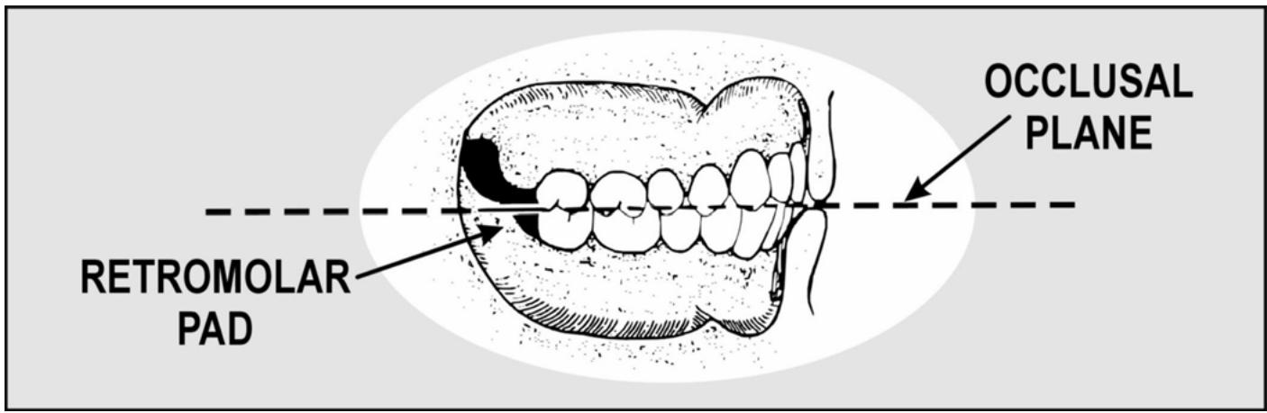
¶ 7.65. Sequence of Arranging Denture Teeth
When individually arranging denture teeth in asystematic, regular sequence, the results are consistently better. One of the following sequences should be used:
7.65.1. Sequence #1 (Most Popular)
One of the most popular, this sequence uses maxillary anterior teeth first and then the maxillary posterior, mandibular posteriors, and mandibular anterior teeth as follows:
7.65.1.1. Set the two maxillary central incisors first and then the lateral incisor and canine on one side. The lateral incisor and canine on the opposite side complete maxillary anteriorsetup.
7.65.1.2. Place the maxillary first premolar, second premolar, first molar, and second molar on one side. Repeat the same sequence for the opposite side. Set maxillary posteriors against the top of a metal template (Figure 7.52).
7.65.1.3. Place the mandibular posterior denture teeth (except the premolars) in the following order. first, set the twofirst molars, bilaterally, next, position the second molar and second premolar on one side, and then position the second molar and second premolar on the other side.
Figure 7.52. Use of a Flat Template (Sequence #1).

7.65.1.4. Place the mandibular anterior denture teeth in the same order as the maxillary anterior denture teeth.
7.65.1.5. Position the mandibular first premolar denture teeth last.
7.65.2. Sequence #2 (Used For 0-Degree Monoplane and 20-Degree Balanced Occlusion)
This sequence is commonly used for setting 0-degree posterior in monoplane occlusions and occasionally used for setting 20-degree posteriors in balanced occlusions. In this sequence, set the maxillary anterior teeth first and then mandibular anterior teeth. A flat metal plate establishes the occlusal plane in monoplane occlusions (Figur e 7.53) and a curved 20-degree plate forms a compensating curve for balanced occlusions (Figure 7.54). Set mandibular denture teeth against the undersurface of the approximate metal template. Set the maxillary posteriors last.
7.65.3. Sequence #3 (Alternate Method)
This sequence is maxillary anterior teeth, mandibular anterior teeth, maxillary posteriors, and mandibular posteriors.
7.65.4. Additional Guidance for Sequences. Some dentists set maxillary anterior denture teeth on the occlusion rim in the patient’s mouth as a first step toward composing a complete setup. For all practical purposes, the rest of the arrangement is done on an articulator. In such situations, it is reasonable to follow arrangement sequence #1. A few dentists set the maxillary and mandibular anterior teeth while the patient is present. Depending on the dentist’s wishes, either sequence #2 or #3 will apply.
¶ 7.66. Compensation for a Lack of Interarch Space
It is common for interarch space to be at a premium in complete denture construction. One solution is to use plastic denture teeth. If that does not help enough, cut out the interfering part of the record base, adapt a piece of tin foil to the cast slightly larger than the cut out area, and set the record base on the cast over the foil. Try to make as conservative a hole in the record base as possible.
Figure 7.53. Use of a Flat Plate for Monoplane Occlusions (Sequence #2).

Figure 7.54. Use of a Curved Plate for Balanced Occlusions (Sequence #2).

¶ Section 7M — Arrangement of Anterior Denture Teeth
¶ 7.67. “Basic” Arrangement (Maxillary)
7.67.1. Other names for this type of maxillary anterior denture tooth alignment are symmetrical arrangement and silver-dollar setup. The term “silver-dollar” setup originated when technicians who prided themselves on their speed rapidly aligned the incisal edges of upper anterior teeth to match the rim of asilver dollar.
7.67.2. Another characteristic of the basic arrangement is that the axial inclinations of the maxillary anterior teeth are mirror images of each other from right to left side (Figure 7.55). This arrangement could represent an 18-year-old person who has perfectly formed teeth in ideal alignment. The arrangement is certainly possible, but it is almost too good to be true. When it is placed in the mouth of an average complete-denture patient who is 35 years or older, the silverdollar setup stands out as false.
Figure 7.55. Axial Inclination of Maxillary Anterior Teethin the “Basic” Arrangement.

7.67.3. The prim ary reason why the silver-dollar setup is put together at all is as a point of departure. The dentist or technician starts with this arrangement and then moves teeth into positions that give the setup more credibility.
¶ 7.68. Guides and Procedures
The guides and procedures for aligning the maxillary anterior teeth are as follows:
7.68.1. Central Incisor. Cut out a block of wax large enough to accommodate the central incisor and seat the tooth in soft wax (Figure 7.56). Po sition the mesial surface on the midline. Position the tooth so the full mesiodistal width of the incisal edge contacts the incisal plane. This automatically tilts the long axis to the distal slightly, the neck of the tooth is somewhat depressed, and the incisal and middle thirds of the labial face are flush with the labial contour of the wax rim. Secure the tooth in place by flowing a small amount of molten wax around it. Position the other incisor in the same way.
7.68.2. Lateral Incisor. Prepare a cutout for the lateral incisor and place it in a bed of soft wax (Figure 7.57). Set the long axis of the lateral at an angle that is more distal to the perpendicular than the central. The incisal edgeshould be about 1 mm above the incisal plane. The neck should be more depressed than the neck of the central in cisor. The incisal third should be flush with the labial contour of the wax rim. Seal the tooth in place.
7.68.3. Canine. The incisal tip of the canine rests on the occlusal plane (Figure 7.58). The long axis is cocked more distal to the perpendicular than the central incisor, but not as much as the lateral incisor. From a labiolingual point of view, the long axis is vertically oriented and the middle third of the labial surface is flush with the wax rim. The canine tooth is located at a corner of the dental arch. In keeping with its position, the canine has two definite planes on its labial face, a mesial plane and a distal plane. Align the mesial plane to follow the curve of the anterior teeth. Align the distal plane with the posterior teeth. Position the lateral incisor and canine on the opposite side and be sure to follow the contour of the occlusion rim (Figure 7.59).
Figure 7.56. Maxillary Central Incisor.

¶ 7.69. “Basic” Arrangement (Mandibular)
7.69.1. When astandardized mandibular tooth arrangement is used, the teeth are positioned on or are slightly facial to the mandibular ridge. If they are lingual to the ridge, they encroach on the space the tongue norm ally occupies. If they are too far facial to the ridge, the lower lip presses against them, and adverse leverages will tend to dislodge the denture.
7.69.2. The distance the maxillary anterior teethex tend over the mandibular anterior teeth in a vertical direction is the vertical overlap. The distance the maxillary anterior teeth project beyond the mandibular anterior teeth in a horizontal di rection is the horizontal overlap (Figure 7.60). When teeth are in centric occlusion, the angle formed with the occlusal plane by a line drawn between the incisal edges of the upper and lower central incisors is the incisal guide angle.
7.69.3. Horizontal and vertical overlap varies with the kind of occlusion being organized (balanced versus monoplane), the posterior tooth mold used (20 degrees versus 30 degrees), and the tooth arrangement sequence em ployed. This pa mphlet explains the details of a number of different complete denture occlusions. A suggest ed tooth sequence and specific directions for setting overlaps are given with the complete denture occlusion being described.
Figure 7.57. Maxillary Lateral Incisor.

¶ 7.70. Guides and Procedures
The guides and procedures for aligning the mandibular anterior teeth are described much like the maxillary anterior teeth.
¶ 7.71. Arch Form and Axial Inclination
The basic, uncharacterized arch form and axial inclination of mandibular anterior denture teeth are shown in Figure 7.61 and as follows:
7.71.1. Central Incisor.
7.71.1.1. The labiolingual inclination is slightly depressed at the neck.
7.71.1.2. The mesiodistal inclination is perpendicular to the occlusal plane.
7.71.1.3. The arch alignment is on the curve of the arch (occlusion rim)
7.71.2. Lateral Incisor.
7.71.2.1. The labiolingual inclination is perpendicular to the occlusal plane.
7.71.2.2. The mesiodistal inclination is aslight disal inclination.
7.71.2.3. The arch alignment is on the curve of the arch (occlusion rim)
7.71.3. Canine.
7.71.3.1. The labiolingual inclination is inclined.
7.71.3.2. The mesiodistal inclination is more distally inclined than the lateral incisor.
7.71.3.3. In the arch alignment, the mesial half of the labial face conforms to the curve of the arch initiated by the incisors. The distal half of the labial surface is angled to match the posterior buccal alignment. NOTE: The two central incisors are us ually set first, the lateral incisor and canine on aside are set next, and the lateral incisor and canine on the opposite side complete the setup.
Figure 7.58. Maxillary Canine.

¶ 7.72. Characterizing Anterior Denture Teeth
Characterization is an attem pt to coordinate the appearance of the prosthesis with the patient’s an atomical measurements, face form, sex, and age. Race is also a consideration when choosing the color of a denture base material.
¶ 7.73. Modifying a Tooth’s Basic Shape (Mold)
The teeth in aset can be ground to produce special effects used for customizing denture tooth arrangements. The objective of characterized arrangement is to harmonize the appearance of the denture teeth with the unique features of the patient and existing dentition, as follows:
7.73.1. Sex. The mesial and distal corners of the maxillary incisors can be rounded to produce a more feminine appearance.
7.73.2. Age. Natural teeth wear down at varying rates as people grow older. One characteristic of age is that the incisal edge of the maxillary lateral incisor touches the occlusal plane. Besides setting the maxillary lateral incisor in this manner, grind the edges of the anterior teeth to simulate wear that is appropriate for the person’s age. Men usually show more wear than wom en of the same age. When grinding the teeth, it is not necessary to grind all of them and no two teeth should be ground in exactly the same way.
Figure 7.59. Completed Maxillary Anterior Setup.

Opposite side central

Opposite side lateral

Labial view - completed anteriorsetup

Occlusal view
¶ 7.74. Organizing a Unique Set of Anterior Teeth Using Size, Shape, and Color Combinations from Different Sets
7.74.1. Size. Wide maxillary lateral incisors are generally thought to be a masculine characteristic. Small, narrow lateral incisors are associated with femininity.
7.74.2. Shape. Square, angular molds are associated with masculinity. The ovoid forms are suppose to suggest femininity.
7.74.3. Color (Shade)
Marked differences in color among anterior teeth are common in older people.
¶ 7.75. Composing a Suitable Arrangement
Arrangement is the manner in which the teeth of a denture relate to the residual ridge and toother teeth within the denture base. Some types of arrangements are as follows:
7.75.1. Basic Arrangement. This is the classical silver-dollar setup which has already been discussed in detail (paragraph 7.67). It is composed of teeth in perfect, symmetrical alignment. If an elderly patient is determined to have this kind of arrangement, grinding individual teeth within the arrangement for sex characteristics and wear patterns makes the setup more believable.
Figure 7.60. Horizontal and Vertical Overlap.

Figure 7.61. Axial Alignment of Mandibular Anterior Denture Teeth.

7.75.2. Vigorous Arrangement. A vigorous arrangement introduces a masculine element if rounded, feminine teeth are used, or it intensifies the masculine image when angular, masculine teeth are used. Some features of a vigorous arrangement are as follows:
7.75.2.1. To show more or less of a tooth’s labial surface can make it look masculine or feminine. The order of increasing masculinity is as follows: The labial face is parallel to the curve of the arch, the distal surface of a tooth is rotated outward, the mesial surface is turned inward, and the mesial surface is lapped by the tooth mesial to it (most masculine).
7.75.2.2. The incisal edge of the maxillary lateral incisor is on the same plane as the maxillary central incisor. NOTE: This is characteristic of masculinity and old age.
7.75.2.3. When the long axis of a maxillary canine is set vertically from a labiolingual view, the orientation is considered neutral. When the inc lination is more facial (protruded at the neck), the effect is more masculine.
7.75.2.4. The use of one or two small diastemas (spaces) can lend vigor to asetup. However, some patients have a fixation for ideal denture setups with chalk-white teeth. This kind of person would strenuously object to spacings between the teetheventhough spaces were present before their natural teeth were extracted. Spacing effects should be used only at the direction of the dentist.
7.75.3. Softened Arrangement. Softened arrangements either in troduces a feminine element when angular masculine teeth are used or intensifies femininity if rounded feminine teeth are used. For the most part, the features of this arrangement are opposite the vigorous type, as follows:
7.75.3.1. The labial face exposure of a tooth, in order of increasing femininity, is as follows. the distal surface is ro tated inward to in crease mesial surface exposure and the mesial surface laps over the distal aspect of the tooth mesial to it (more feminine).
7.75.3.2. The incisal edge of the latera l incisor is raised above the plane of the central incisor. (This is also a youthful characteristic.)
7.75.3.3. The long axis of a maxillary canine set vertically from a labiolingual view is considered neutral. Using this orientation as the baseline, the set of the canine is made feminine by depressing the neck.
7.75.4. Asymmetrical Arrangements. All tooth arrangements should be somewhat asymmetrical when the right and left sides of the setup are co mpared. However, the variety called asymmetrical is very obviously so. Facial asymmetry is more noticeable in some people than inothers. One side of the face may be more angular or maybe even larger than the other side. It is co mmon to assign male characteristics to the shap e and arran gement of teeth on the ha rd side and fem ale characteristics to the tooth shapes and arrangement on the soft side. A te chnician might make a personal decision for a vigorous or a soft arrang ement, but the dentist usually makes aspecif ic request for the asymmetrical variety.
7.75.5. Crowded Arrangement. Crowding is usually aresult of natural teeth that are too large for the size of the arch. Also, a patient’s natu ral mandibular anterior teeth become increasingly crowded as the patient becomes older. This arrangement shows generalized, moderate, and proximal overlapping of many of the anterior teeth.
7.75.6. Spaced Arrangement.
7.75.6.1. In the natural state, crowding is probably the result of large teeth in a small arch. Looking at the opposite situation, small teeth situated in a large arch often show considerable spacing among them.
7.75.6.2. Even though either condition could be there naturally, it is difficult to get patients to accept such arrangements in dentures because they tend to think crowding or spacing is ugly and usually want these features eliminated in artificial setups. Do not take the liberty of putting such arrangements together without very specific directions from the dentist. NOTE: Trying to create a to tally masculine or totally f eminine effect is usually a m istake. Few m en present an absolutely perfect masculine image and the same is true of wom en and fe mininity. Most teeth show a majority of characteristi cs associated with their respect ed sex and a few traits of the opposite sex.
¶ Section 7N — Balanced Complete Denture Occlusions
¶ 7.76. Goal of Complete Balanced Denture Occlusion
7.76.1. The goal in co mpletely balanced denture occlusions is top roduce multiple contacts between maxillary and mandibular teeth in anterior and posterior areas, on the right and on the left, in lateral and protrusive excursions. Cusped teeth (33, 30, or 20 de grees) are usually used in balanced occlusions although 0-degree teeth can be used for this purpose.
7.76.2. In order for denture teeth to achieve maximum contact in all mandibular positions, a compensating curve must be incorporated into the posterior segments of the denture occlusion. When the molars are set with the compensating curve fully formed, the distobuccal cusp of the maxillary second molar must be no higher than the highest part of the retromolar pad.
7.76.3. Initial development of the occlusal plane begi ns with the incisors and premolars. After the second premolars are set, the posterior projection of the occlusal plane should hit two-thirds of the way up the retromolar pads. If the plane is not properly begun with the incisors and premolars, there is a chance of coming out too low or too hi gh in relation to the pad s after the compensating curve is formed.
7.76.4. Set the maxillary anterior teeth first (paragraph 7.67), followed by the maxillary posteriors. Center the fossae and central groove of the maxillary posteriors over the crest of the mandibular ridge, buccolingually. The buccal aspect of the maxillary posteriors must not be set lateral to a line dropped perpendicular into the depth of the maxillary buccal sulcus. Do not set teeth on the tuberosities.
7.76.5. Next, set the mandibular posteriors. Situate the buccal cusps over the crest of the ridge. Do not set teeth on the retromolar pads. When setti ng the low er teeth to develop lateral ex cursion balance, be sure to incorporate sideshift into the lateral test movements. To get full sideshift value, follow the directions in paragraph 6.21. Complete the setup by positioning the mandibular anterior teeth.
¶ 7.77. Arrangement of Cusped Maxillary Posterior Teeth
Remove the occlusion rim from the mandibular cast. Find the longest straight segment of the residual ridge on the right and left sides. Place reference marks on the anterior and posterior land areas of the cast. Return the mandibular occlusion rim to the cast. Using the reference marks as guides, register the right and left crests of the residual ridge on the top surface of the mandibular occlusion rim. Position each maxillary posterior denture tooth on one side, one at a time, relative to the crest of the mandibular ridge and in relation to a flat metal plate which represents the occlusal plane (Figures 7.47 and 7.52), as follows:
7.77.1. Recommend Space Inclusion. Create a 0.5 mm space between the distal surface of the maxillary canine and the mesial of the first premolar. The space makes the final positioning of the mandibular first premolar tootheasier. Set all upper posteriors in proximal contact.
7.77.2. Forming the Compensating Curve Pattern for All Cusped Maxillary Posteriors (Except Pilkington-Turner 30-Degree Teeth)
(NOTE: See Figures 7.62 through 7.64.)
7.77.2.1. Maxillary First and Second Premolars. Place the maxillary first premolar with its long axis at right angles to the occlusal plane. Place the buccal and lingual cusps on the plane. Position the maxillary second premolar in asimilar manner.
7.77.2.2. Maxillary Molars. Arrange the buccal cusps of the molars to form an angle of about 6 degrees with the occlusal plane, beginning at the buccal cusp of the second premolar. Place the mesiolingual cusp of the first molar on the plane. Starting with this cusp, the remaining lingual cusps should form an angle of 6 degrees with the plane and be more or less parallel with the line of the buccal cusps. The mesiolingual cusp of the first molar touches the plane, and the mesiobuccal cusp is raised 0.5 mm out of contact. The disto lingual cusp is raised 0.5 mm and the distobuccal cusp is 1 mm off the plane. The mesiolingual cusp of the second molar is 0.75 mm off the plane, and the mesiobuccal cusp is 1.25 mm raised out of contact. The distolingual cusp is raised 1.5 mm.
7.77.3. Pilkington-Turner 30-Degree Maxillary Posteriors. The compensating curve characteristics of Pilkington-Turner teeth differ slightly from other cusped forms (Figure 7.65), as follows:
7.77.3.1. Maxillary First and Second Premolars. From a facial view, the long axes of the premolars are perpendicular to the plane. The lingual cusps of the first and second premolars touch the plane, and the buccal cusps are raised 0.5 mm.
7.77.3.2. Maxillary First Molar. The mesiolingual cusp touches the plane, and the mesiobuccal cusp is raised 0.5 mm out of contact. The distolingual cusp is raised 0.5 mm, and the distobuccal cusp is 1 mm off the plane.
7.77.3.3. Maxillary Second Molar. The mesiolingual cusp is 0.75 mm off the plane, and the mesiobuccal cusp is 1.25 mm raised out of contact. The distolingual cusp is 1 mm off, and the distobuccal cusp is raised 1.5 mm.
Figure 7.62. Maxillary Arch Arrangement of Cusped Posterior Teeth (Except Pilkington-Turner Posteriors).

COMPENSATING CURVE

FIRST AND SECOND BUCCAL ALIGNMENTS

FIRST AND SECOND PREMOLARS

FIRST MOLAR

SECOND MOLAR
RELATIONSHIP TO MANDIBULAR RIDGE CREST
7.77.4. First and Second Buccal Alignments. The buccal alignment of maxillary posterior denture teethis the same for all cusped forms, as follows:
7.77.4.1. First Buccal Alignment. Align the labial ridge of the canin e, the buccal ridges of the first and second premolars, and the mesial buccal ridge of the first molar (Figure 7.63-C).
7.77.4.2. Second Buccal Alignment. Align all four buccal ridges of the molars so they are on a separate straight line from the first alignment (Figure 7.63-E).
7.77.5. Stabilizing the Alignment. After setting both sides of the maxillary arch, flow wax around the collars of the teeth to fix them in place securely. Few (if any) changes should be necessary in the maxillary arch from this point on.
Figure 7.63. Setting Maxillary Left Posterior Teeth Using a Flat Template.

¶ 7.78. Setting Cusped Mandibular Posterior Teeth for Balance
The procedures for developing balance are the same for all cusped teeth. To get an idea of what is expected, paragraphs 7.78.1.1 through 7.78.1.4 depict typical centric, working, balancing, and protrusive excursion contacts (occlusions), respectively. Carefully and closely follow these directions for setting each kind of tooth.
7.78.1. Mandibular Left First Molar.
7.78.1.1. Centric Occlusion (Figure 7.66)
Attach a cone of soft wax to the left mandibular first molar. Place the tooth on the mandibular record base in the approximate position it will assume in centric occlusion. Closethe articulator. From the buccal view, while the wax is still soft, position the tooth so the mesiolingual cusp of the maxillary first molar seats in the central fossa of the mandibular first molar. The triangular ridge of the mesiobuccal cusp of the upper first molar rests in the buccal development groove of the lower first molar. From the lingual view, the mesiolingual cusp of the upper first molar is seated in the central fossa of the lower and the mesiolingual cusp of the lower first molar fills the lingual embrasure between the upper second premolar and the first molar.
Figure 7.64. Completed Maxillary Arch Setup.

Figure 7.65. Maxillary Arch Arrangement of Pilkington-Turner Posterior Teeth.

7.78.1.2. Working Occlusion (Figure 7.67)
Lock down the condyle element, release the right condyle element, and move the upper member to the right. Always incorporate sideshift during the right working movement by pushing the condylar guide to the right. From the buccal view, the working relation of the lower first molar ag ainst the upper first molar shows mesial and distal cusp ridges of buccal cusp s in contact. The mesial cusp ridge of the mesiobuccal cusp of the mandibular first molar contacts the distal cusp ridge of the buccal c usp of the maxillary second premolar. From the lingual view, the mesiolingual cusp of the upper first molar contacts the cusp ridges thathelp form the lingual developmental groove of the lower first molar.
Figure 7.66. Mandibular First Molar (Centric Occlusion).

7.78.1.3. Balancing Occlusion (Figure 7.68)
To establish balancing contacts, lock the right condyle element down and release the one on the other side. Move the upper member to the left with one hand while pushing the condylar guide to the left with the thumb of the other hand. From a buccal view, the mesiolingual cusp of the maxillary first molar slides through the distobuccal groove of the lower first molar, and the lingual cusp of the maxillary second premolar contacts the mesial incline of the tr iangular ridge associated with the lower first molar’s mesiobuccal cusp.
7.78.1.4. Protrusive Occlusion (Figure 7.69)
From the buccal view, the mandibular buccal cusps contact the distal inclines of the cusp ridges in the maxillary arch. From the lingual view, the maxillary lingual cusps contact the mesial inclines of the cusp ridges in the opposing arch.
7.78.2. Mandibular Right First Molar. Follow the same directions as for setting the lower left first molar (paragraph 7.78.1).
Figure 7.67. Balanced Occlusion (Working Position).

Figure 7.68. Balanced Occlusion (Balancing Position).

Figure 7.69. Balanced Occlusion (Protrusion).

7.78.3. Set the Incisal Guide Table. After the lower r ight and left first molars are positioned in the setup, set the incisal guide table as follows:
7.78.3.1. Adjust the table to match the incisal guide pin’s protrusive rise.
7.78.3.2. Adjust the wings to match the incisal guide pin’s rises to the right and left. The protrusive slant of the incisal guide table and the wing adjustments should be set so they are barely in contact with the pin. The adjusted table and wings help maintain the teeth previously set in their original positions.
7.78.4. Mandibular Left Second Molar. Open the articulator. Attach a softened piece of wax to the mandibular second molar. Position the tooth distal to the mandibular first molar on the record base.
7.78.4.1. Centric Occlusion (Figure 7.70)
From the buccal view, the triangular ridge of the mesiobuccal cusp of the upper second molar rests in the buccal groove of the lower second molar. The mesiobuccal cusp of the lower second molar fits between the maxillary first and second molars and contacts their marginal ridges. From the lingual view, the mesiolingual cusp of the maxillary se cond molar fits direc tly into the central fossa of the mandibular secon d molar.
Figure 7.70. Mandibular Second Molar (Centric Occlusion).

Ridge relation

Placement

Buccal view

Lingual view
7.78.4.2. Working Occlusion (Figure 7.67)
Move the upper member of the ar ticulator to make the left side of the ar ranged teeth, the working side. From the buccal view the working relation of the lower second molar against the upper second molar has mesial and distal cusp ridges of buccal cusps in contact. The mesial cusp ridge of the mesiobuccal cusp of the mandibular second molar contacts the distal cusp ridge of the distobuccal cusp of the maxillary first molar. From the lingual view the mesiolingual cusp of the upper second molar contacts the cusp ridges that form the lingual developmental groove of the lower second molar.
7.78.4.3. Balancing Occlusion (Figure 7.68)
Move the upper member of the articulator to make the left side of the arranged teeth, the balancing side. In the buccal view, the mesiolingual cusp of the upper molar slides through the distobuccal groove of the lower second molar. The distolingual cusp of the upper first molar contacts the mesial incline of the triangular ridge of the mandibular second molar’s mesiobuccal cusp.
7.78.4.4. Protrusive Occlusion (Figure 7.69)
From the buccal view, the mandibular buccal cusps contact the distal inclines of the cusp ridges in the maxillary arch. From the lingual view, the ML cusps contact the mesial inclines of the cusp ridges in the opposing arch.
7.78.5. Mandibular Left Second Premolar. Open the articulator to position the left second premolar. Attach a piece of softened wax to the premolar and position it on the record base mesial to the first molar. Align the facial cusp anterioposteriorly with the buccal cusp of the lower first molar.
7.78.5.1. Centric Occlusion (Figure 7.71)
From the buccal view, close the articulator and adjust the mandibular second premolar to make its buccal cusp fit between the maxillary first and second premolars. The tip of the cusp contacts the mesial marginal ridge of the upper second premolar as well as the distal marginal ridge of the upper first premolar. From the lingual view, the lingual cusp is located at the lingual em brasure between the upper first and second premolars.
7.78.5.2. Working Occlusion (Figure 7.67)
Move the upper member of the ar ticulator to make the left side the working side. From the buccal view, the distal cusp ridge of the mandibular second premolar’s buccal cusp contacts the mesial cusp ridge of the maxillary second premolar’s buccal cusp. The mesial cusp ridge of the lower second premolar’s buccal cusp contacts the distal cusp ridge of the maxillary first pr emolar’s buccal cusp. From the lingual view, the lingual cusp of the lower second premolar moves further into the em brasure between the maxillary first and second premolars.
7.78.5.3. Balancing Occlusion (Figure 7.68)
Move the upper member of the articulator to make the left side the balancing side. The mesial incline of the lower second premolar’s buccal cusp triangular ridge contacts the lingual cusp of the upper first premolar.
7.78.5.4. Protrusive Occlusion (Figure 7.69)
The mandibular buccal cusps contact the distal inclines of cusp ridges in the maxillary arch. The ML cusps contact the mesial inclines of cusp ridges in the opposing arch.
7.78.6. Mandibular Right Second Molar and Second Premolar. Set theseteeth in centric occlusion (Figure 7.72). Adjust them for working and balancing contacts.
7.78.7. Mandibular First Premolars. The only mandibular posterior teeth remaining to be placed are the first premolars. Position them after the mandibular anterior teeth are arranged. It is sometimes necessary to reduce the mesiodistal dimensions of the mandibular first premolar to fit it in place (Figure 7.73). After the mandibular anteri or teeth are set, orient the mandibular first premolars in the following manner:
Figure 7.71. Mandibular Second Premolar (Centric Occlusion).

Ridge relation

Placement

Buccal view

Lingual view
7.78.7.1. Centric Occlusion. Adjust the mandibular first premolar so its buccal cusp f its between the maxillary canine and first premolar when the articulator is closed.
7.78.7.2. Working Occlusion. The mesial cusp ridge of the mandibular first premolar’s buccal cusp contacts the distal cusp ridge of the maxillary canine. The distal cusp ridge of the mandibular first premolar’s buccal cusp contacts the mesial cusp ridge of the maxillary first premolar.
7.78.7.3. Balancing Occlusion. The mandibular first premolar has no balanci ng contact with the maxillary teeth during a balancing excursion.
7.78.7.4. Protrusive Occlusion. The mesial cusp ridge of the mandibular first premolar’s buccal cusp contacts the distal cusp ridge of the maxillary canine.
Figure 7.72. Right Side Mandibular Posterior Teeth (Centric Occlusion).

Figure 7.73. Positioning the Mandibular First Premolars.

¶ 7.79. Setting Mandibular Anterior Teeth for Balance
At this point, the upper anterior teeth, upper posteriors, and lower posteriors are set. After the ri ght and left first molars are placed, the working, balancing, and protrusive rises out of centric occlusion are determined for the remaining teeth in the setup. The incisal guide table and wings are then adjusted to prevent teeth from shifting in soft wax. The lower second molars and premolars are set to match the rises. For the lower anterior teeth, follow these procedures:
7.79.1. Centric Occlusion.
7.79.1.1. Overall Alignment. Use the basic alignment pattern discussed in paragraphs 7.72 through 7.75.6.2 and shown in Figure 7.61. Also see Figure 7.74.
7.79.1.2. Horizontal Overlap. Between 1 and 2 mm of horizontal overlap is an acceptable range in all cases where the ridges are normally related (Class I). Class II ridge relations require more than a 2 mm horizontal overlap. The incisors are edge to edge in Class III ridge relations.
7.79.1.3. Vertical Overlap. The amount of vertical overlap can be expected to change directly withincreases or decreases in posterior cusp height. The 30-degree posteriors can g enerate as much as 2 mm of vertical overlap between upper and lower an terior teeth. When 20-degree posteriors are used, the amount of vertical overlap required might be 1 mm. The rule of thumb is since horizontal overlap is more or less standa rd for normal ridge relations (1 to 2 mm), use enough vertical overlap to make the anterior teeth balance in working and protrusive contact relations.
7.79.2. Working Occlusion (Figure 7.67)
When the anterior teeth are in a right or left working test position, the labioincisal edges of the mandibular central and lateral incisors are in contact with the linguoincisal edges of the maxillary central and lateral incisors on the working side. The mandibular canine inter digitates with the d istal portion of the maxillary latera l in cisor’s in cisal edge and the mesial cusp ridge of the maxillary canine. In the posterior segments, the teeth show working side contacts characteristic of balanced occlusion.
7.79.3. Balancing Side Occlusion (Figure 7.68)
The maxillary anterior teeth do not contact the mandibular anterior teeth on the balancing side. The lingual cusps of the maxillary posterior teeth are in contact with the buccal cusps of opposing mandibular posterior teeth.
7.79.4. Protrusive Occlusion (Figure 7.69)
When the anterior teeth are in the protrusive test position, the maxillary and mandibular incisors touch, edge to edge. The mesial cusp ridge of the mandibular canine contacts the distal part of the maxillary lateral incisor’s incisal edge. Simultaneously, the buccal cusps of posterior teeth are in contact, ju st shor t of a tip to tip orientation.
¶ 7.80. Balanced Complete Denture Occlusion Using 0-Degree Teeth
7.80.1. The maxillary anterior teeth are set to achieve the desired esthetic result. The mandibular anterior teeth are arranged in centric occlusion with an amount of horizontal overlap that fits the occlusal classification of the patient (for example, Class I is 1 to 2 mm). A slight amount of vertical overlap is incorporated (0.5 - 1 mm).
7.80.2. The occlusal plane is formed by using a 20-degree curved plate positioned on the incisal edges of (mandibular) anterior teeth and the highest part of both retromolar pads (Figure 7.54). The buccal cusps of the mandibular posteriors are placed in as traight line over the crest of the mandibular ridge. The teeth are set so the occlusal surfaces contact the undersurface of the template. The upper posteriors ar e articulated with the lower posteriors to complete the setup. Make sure there is at least 1 mm of horizontal overlap in the posterior segments of the setup to prevent cheek biting.
7.80.3. The vertical overlap between the upper and lower anterior teethis readjusted for balance. The objective is multiple contacts on the r ight and left in anterior and posterior areas during working, balancing, and protrusive occlusion.
Figure 7.74. Setting Mandibular Anterior Teethin Centric Occlusion.

¶ Section 7O — Monoplane Complete Denture Occlusion
¶ 7.81. Overview
In the expression monoplane occlusion it is im plied that 0-degree (no cusps) posterior teeth are used. In this denture occlusion, 0-degree teeth are set on a flat plane (no compensating curve).
¶ 7.82. Tooth Contact Characteristics
7.82.1. Anterior Teeth. In centric occlusion, anterior teeth normally have a vertical overlap of 0.0 mm and 1 to 2 mm of horizontal overlap.
7.82.2. Working Side. There are is olated, unprogrammed contacts among a few upper and low er teeth on the working side.
7.82.3. Balancing Side. On the balancing side, there is us ually no contact between any of the upper and lower teeth.
7.82.4. Protrusive. When the incisors are edge to edge, there is no contact posteriorly.
¶ 7.83. Advantages of Monoplane Dentures
7.83.1. Monoplane dentures are somewhat easier to set than completely balanced dentures.
7.83.2. Monoplane dentures function well in almost all patients. It is the denture occlusion of choice for patients with poor ridges. A set of monoplane dentures minimizes horizontal pressures on the residual ridge. Due to the absence of inclined planes, the ridges are sub ject to vertical pressures which are considered less damaging.
7.83.3. The monoplane principle is the denture occlusion of choice for Class II and Class III jaw relationships. It is the denture occlusion of choice for crossbite cases.
¶ 7.84. Disadvantages of Monoplane Dentures
7.84.1. The 0-degree teeth don’t look as natural as cusped teeth.
7.84.2. The 0-degree teeth might not break up food as well as cusped teeth.
7.84.3. Monoplane dentures have more of a tendency to tip than balanced complete dentures. The lack of protrusive balance is a special invitation to tipping.
¶ 7.85. Articulator Settings
Horizontal condylar guidance is set at 30 degrees, lateral condylar guidance is set at 15 degrees, and the incisal guide table is set at 0 degrees.
¶ 7.86. Denture Tooth Setting Order
Centric occlusion is the only position in which there are multiple, evenly distributed contacts between maxillary and mandibular teeth, and these contacts appear in the posterior areas.
7.86.1. Maxillary Anterior Teeth. Set the maxillary anterior teeth to match the c ontour of the occlusion rim.
7.86.2. Mandibular Anterior Teeth (Centric Occlusion Position)
A standard alignment pattern is used with 0 mm vertical overlap. The horizontal overlap is highly variable and depends on the patient. (For example, Class I is 1 mm, Class II is 5 mm or more, and Class III is 0 mm.) The facial aspect of the mandibular anterior teeth should not exte nd forward of a line dropped perpendicular from the occlusal plane to the mandibular labial sulcus.
7.86.3. Mandibular Posterior Teeth. The buccal cusps of the mandibular posteriors should be set over the crest of the ridge. The front part of a flat plate is set on the incisal edges of the mandibular anterior teeth, and the posterior part of the plate is s et at the heights of the retromolar pads. The mandibular posteriors area m anaged to contact the undersurface of the plate (Figure 7.54). The distofacial plane of the mandibular canine and the buccal surfaces of the mandibular posteriors fall on a straight line (no second buccal alignment).
7.86.4. Maxillary Posterior Teeth (Centric Occlusion Position)
The buccal aspect of the maxillary posteriors should not be set lateral to a line dropped perpendicular from the occlusal plane into the depth of the buccal sulcus. The maxillary posteriors are positioned to make maximum contact with the mandibular posteriors. At least a 1 mm horizontal overlap is included in the posterior segments to prevent cheek bitin g (Figure 7. 75). When cusped teeth are used, the cusps in one quadrant have to fit intofossae and e mbrasures of teeth in the opposing quadrant. This kind of relations hip is desirable, but not m andatory with 0-degree teeth. From an anterioposterior point of view, 0- degree cusps in one quadrant do not have to fit into embrasures and fossae in the other.
¶ 7.87. Problem of Protrusive Balance
7.87.1. The heels of monoplane mandibular dentures ha ve a tendency toflip up when anterior teeth are brought intoprotrusive contact. To co mpensate for a lack of protrusive balance in monoplane dentures, dentists sometimes request a modification of the flat plane principles.
7.87.2. The plane of occlusion is set flat in the premolar and first molar areas. However, the maxillary and mandibular second molars are s lanted enough in centric occlusion (approximately 15 degrees) to produce bilateral posterior contact when the incisors are in protrusive (edge to edge) occlusion (Figure 7.76). The slanting of the maxillary and mandibular second molars creates a very limited Curve of Spee thathelps overcome the Christensen’s Phenomenon.
Figure 7.75. Posterior Horizontal Overlap of Flat Plane Teeth.

Figure 7.76. Protrusive Balance Compensation in Monoplane Denture Occlusions (Second Molar Slant).

¶ Section 7P — Crossbite Complete Denture Occlusion
¶ 7.88. Crossbite Condition in the Natural Dentition
7.88.1. Anterior Crossbite. One o r more of the mandibular teeth are facial to the maxillary anteriors instead of being positioned in the normal facial-lingual relationship.
7.88.2. Posterior Crossbite. The normal buccolingual relationship of mandibular to maxillary posterior teethis reversed. That is, instead of having the buccal cusps of mandibular posteriors hitting in the fossae and marginal ridge areas of maxillary teeth, the buccal cusps of the maxillary posteriors occlude in the fossae and marginal ridge areas of mandibular posteriors.
7.88.3. Crossbite Variations. Crossbite relations may be limited exclusively to the an terior area. The condition might be present in the posterior area of one side onl y, in the anterior area on one side only, or in the posterior segments of both sides and in the entire anterior region.
¶ 7.89. Crossbite Condition in Complete Denture Construction
In this condition, the arch form of the mandibular residual ridge appears to be la rger than the arch form of the maxillary. Two reas ons why maxillary and mandibular ridge relations might dictate denture tooth crossbite are as follows:
7.89.1. When natural teeth that have been in cro ssbite are extracted, the residual ridges will probably be in crossbite.
7.89.2. Maxillary and mandibular ridges that might have been norm ally oriented at one time can change into a crossbite relationship because of drastic resorption in the maxillary and mandibular arches. (That is, the upper arch narrows and the lower arch widens.) Sometimes, crossbite ridge relationships are only marginally abnormal. To make a rational decision for or against a crossbite denture occlusion, an imaginary line perpendicular to the occlusal plane is extended into the depth of the maxillary buccal sulcus. If the buccal surfaces of the maxillary posterior teeth have to be set laterally to that line for their sulc i to fall over the cres t of the mandibular ridge, the ridges are in enough crossbite to justify setting a crossbite denture occlusion.
¶ 7.90. The 0-Degree Teeth Set in Crossbite (Monoplane Arrangement)
7.90.1. Articulator Settings. Horizontal condylar guidance is set at 30 degrees, lateral condylar guidance is set at 15 degrees, and incisal table is set at 0 degrees.
7.90.2. Denture Tooth Setting Order. Centric occlusion is the onl y position in which the re are multiple, evenly distributed contacts between maxillary and mandibular posterior teeth as follows:
7.90.2.1. Maxillary Anterior Teeth. The maxillary anterior teeth are set to match the contour of the occlusion rim.
7.90.2.2. Mandibular Anterior Teeth (Centric Occlusion Position)
Use astandard alignment p attern with 0 mm vertic al overlap. The horizontal overlap is highly variable and depends on the type case being set Class I-1 mm; Class III-0 mm) or perhaps the use of a negative horizontal overlap. A nega tive ho rizontal overlap is where the incisal ed ges of the mandibular anterior teeth are forward of the maxillary anterior teeth in ce ntric occlusion. It is not unusual to need a mandibular an terior tooth for m with a larg er mesiodistal width than the manufacturer’s guide suggests.
7.90.2.3. Mandibular Posterior Teeth. The buccal cusps of the mandibular posterior teeth are set over the crest of the mandibular ridge. Set the front part of a flat plate on the incisal edges of the mandibular anterior teeth and situate the posterior part of the plate at the heights of the retromolar pads. Arran gethe mandibular posterior teeth to contact the undersurface of the plate. Sometimes the posterior re sidual ridge segments in these cases are so long that a third mandibular premolar is added to the setup.
7.90.2.4. Maxillary Posterior Teeth. The maxillary arch in these kinds of cases can be ra ther small. It might be necessary to omit premolar teeth from the setup. Position the maxillary posterior teeth to make maximum contact with the mandibula r posteriors. Be sure to incorporate at least 1 mm of ne gative horizontal overlap in the posterior segments to prevent cheek biting.
7.90.2.5. Supplemental Considerations (Figure 7.77)
Figure 7.77. Flat Plane Posteriors Set in Posterior Crossbite.

7.90.2.5.1. When a norm al upper to lower ridge relationshi p exists in the anterior area, it is necessary to provide a “crossover” where the buccal cusps of mandibular teeth, which negatively overlap maxillary teeth, cross the line of the maxillary buccal cusps to blend with the incisal edges of mandibular anterior teeth. This is usually done by setting the mandibular second premolar in an end-to -end relationship to the maxillary first and second premolars and completing the “crossover” with the mandibular first premolar (Figure 7.78)
Figure 7.78. The 30-Degree Posteriors in Crossbite (Quadrant Reversal Arrangement).

7.90.2.5.2. People with anterior c rossbites usually have a limited ability topro trude the lower jaw. Protrusive balance problems are rarely a concern.
¶ 7.91. Cusped Teeth Set in Crossbite
7.91.1. Quadrant Reversal Arrangement, Using 30-Degree Posteriors.
7.91.1.1. In this procedure, the maxillary left posterior denture teeth are set on the mandibular right side, the maxillary right denture teeth are set on the mandibular left side, the mandibular left teeth are set on the maxillary r ight s ide, and the mandibular right teeth are set on the maxillary left side (Figu re 7.78). The tooth setting sequence is maxillary anteriors, mandibular anteriors, mandibular posteriors, and maxillary posteriors.
7.91.1.2. Develop the o cclusal plane by setting the lower posterior teeth on the crest of the mandibular ridge, again st the undersurface of a 20-degree curved plate. The three points that determine the plane ar e the mandibular anterior teeth and bilaterally the heigh ts of the retromolar pads. The posterior teeth in the maxillary arch are set with their buccal cusps in the fossae and embrasures of the mandibular teeth, thus reversing the norm al stamp cusp and shearing cusp relationships.
7.91.1.3. It might be necessary to provide a “cro ssover” point—aspecific area of transition, usually located in the premolar regions, wh ere the negatively overlapping buccal cusps of mandibular posterior teeth in cros sbite “c rossover” the line of the maxillary bucc al cusps to blend with the mandibular anterior teeth. Excep t for the significant differences mentioned, the arrangement of the teethis very similar to that of a nor mal case in characteristics such as compensating curve and general alignment prin ciples. I t is dif ficult, b ut possib le, to cr eate balanced complete dentures with this setup.
7.91.2. Standard Arrangement, Using 20-Degree Posteriors.
7.91.2.1. Denture teeth occupy their ordinary places in a dental arch without the quadrant reversal just described. However, the norm al stamp cusp and shearing cusp relationships are reversed (Figure 7.79). When this method is used, a mandibular tooth one size larger than the maxillary tooth is so metimes necessary, de pending on the d ifference in size between the maxilla and mandible.
Figure 7.79. The 20-Degree Teethin Crossbite (Standard Arrangement).

7.91.2.2. The tooth setting order is maxillary anteriors, maxillary posteriors, mandibular posteriors, and mandibular anteriors. The maxillary anterio rs are set for the desired esthetics. The upper posteriors are positioned so the buccal cusps are directly over the crest of the mandibular ridge. Create the first and second buccal align ments typical of cusped maxillary posteriors.
7.91.2.3. Use a flat plate as a guide in devel oping the occlusal plane and associated compensating curve. The three points that de termine the plane of occlusion are the upper anterior teeth and points found bilaterally two-thirds of the way up the retromolar pads.
7.91.2.4. Set the mandibular posteriors so the buccal cusps of the maxillary posteriors hit in the fossae and embrasures of the mandibular posterior teeth. Set the mandibular teeth for acceptable esthetics. If normal anterior horizontal and vertical overlaps are indica ted, position the premolars to achieve asmooth “crossover.”.
¶ Section 7Q — Lingualized Complete Denture Occlusion
¶ 7.92. Definition
A balanced (bilateral) occlusion is founded on maxillary posterior lingual cusps contacting mandibular posterior fossas. A lingualized occlusion is a compromise, using anatomic and nonanatomic posterior tooth forms.
¶ 7.93. Lingualized Denture Occlusion Technique
The lingualized denture occlusion technique uses 20-, 30-, or 33-degree maxillary posterior teeth a rranged along astandard compensating curve. The maxillary posteriors are set against 0-degree mandibular posterior teeth with only the lingual cusps of the maxillary posterior teeth contacting their o pponents in centric occlusion (Figure 7.80). In lateral excursions, the overall effect resembles bilateral balance.
Figure 7.80. Posterior Tooth Relationship (Lingualized Occlusion).

¶ 7.94. Advantages of the Technique
7.94.1. It can be used in most denture combinations and easily adapted for Class II and III patients.
7.94.2. It uses cusped maxillary teeth. This is particularly helpful when the patient places a high priority on esthetics and a nonanatomic occlusal scheme is indicated by oral conditions such as severe alveolar ridge resorption. The cusp form is more natural in appearance compared to nonanatomic tooth forms.
7.94.3. It maximizes cutting efficiency with minimized lateral forces.
7.94.4. Bilateral mechanical balanced occlusion is readily obtained.
¶ 7.95. Disadvantages of the Technique
7.95.1. Tipping of the denture while functioning can result with improperly set denture teeth.
7.95.2. Some modification of mandibular posterior teeth may be required before setting of the denture teeth can begin.
¶ 7.96. Setting the Lingualized Denture
7.96.1. Start with the casts and occlusion rims mounted on asem i-adjustable articulator. Ensure the articulator settings are 30 degrees horizontal and 15 degrees lateral if nofurther guidance is provided by the dentist.
7.96.2. Set maxillary and mandibular anterior teeth first, using Sequence #2 (paragraph 7.65.2)
7.96.3. Maxillary tooth setup should be in alig nment with the labial contour of the maxillary occlusal rim.
7.96.4. Ensure a 1 mm vertical and horizontal overlap for esthetics. Vertic al overlap exceeding 1 mm may jeopardize the balance during excursive movements, causing denture dislodgment.
7.96.5. Open the occlusal vertical dimension prior to setting posterior teeth by lowering the incisal guide pin.5 mm. This will allow adequate room for selective grinding of posterior teeth.
7.96.6. Begin setting mandibular posterior teeth using a 20-degree curved template. Position the posterior of the template at the height of the retromolar pads and ensure the anterior portion of the template rests on the incisal edges of the mandibular anterior teeth. Proceed with setting mandibular posterior teeth described in Sequence #2, ensuring the central sulcus is placed over the crest of the mandibular ridge.
7.96.7. Position maxillary posterior teeth on the occlusion rim and observe the following guidelines.
7.96.7.1. Position the stamp cusps into the central sulcus areas of the opposing mandibular teeth (Figure 7.81), which will ensure chewing forces are directed over the crest of the ridge only.
7.96.7.2. Elevate the shearing cusp approximately 1 mm to avoid any contact with the opposing denture teeth (Figure 7.81)
NOTE: No conta ct will ex ist at anytime between maxillary shearing cusps and mandibular denture teeth.
¶ 7.97. Restoring Occlusal Vertical Dimension
7.97.1. Close vertical dimension by raising the incisal guide pin.5 mm.
7.97.2. Occlude dentures with articulating paper grinding high spots in sulcus of mandibular posteriors. Deepen fossa or grind inclines marked by articulating paper until the pin touches the table. At no time should the maxillary stamp cusps be ground upon (ex cept during final selective grinding when there has been obvious tooth movement during processing of the denture base).
¶ 7.98. Tooth Contact Characteristics
7.98.1. Working Side. Working side contacts will result from the lingual inclines of the maxillary lingual cusps contacting the lingual cusp regions of the mandibular teeth in lateral excursions.
7.98.2. Balancing Side. Contacts will result from the buccal inclines of the lingual cusps on the maxillary teeth gliding across the buccal cusp regions of the mandibular teeth in lateral excursions.
7.98.3. Protrusive. Anterior and posterior contacts should be evenly distributed to prevent tipping of the denture.
Figure 7.81. Maxillary Arch Arrangement for Lingualized Occlusion.

¶ Section 7R — Wax Trial Dentures
¶ 7.99. Wax Pattern of the Denture Base (Wax-Up)
7.99.1. A wax-up is formed around a completed tooth arrangement. The pattern is asim ulation of soft tissues attached to the teeth, alveolar processes, and palate. The combination of teeth and waxup on arecord base is called a trial denture because the dentist tests its appearance and function in the patient’s mouth.
7.99.2. The trial denture then becomes a pattern for for ming a mold. Denture base plastic is converted from a dough to asolid in the mold. Based on this series of events, there are two places in a complete denture procedure where soft tissue contours must be simulated in wax—the wax-up for try-in (paragraph 7.100) and the final wax-up (paragraph 7.101).
7.99.3. The dentist usually requests a try-in after the denture teeth are set in occlusion on the record base. The wax-up is usually not characterized because the dentist often makes changes to this trial denture. The evaluation of the wax trial denture in the patient’s mouth permits the dentist to establish the final tooth position. After the try-in and before wax denture investing procedures, a detailed final wax-up is done.
7.99.4. Waxing and contouring procedures reproduce the appearance of natural gingival tissues as closely as possible. The external surfaces of the denture bas es are shaped toprom ote cleanliness and denture retention.
¶ 7.100. Wax-Up for Try-In
The wax-up is of the basic, standardized variety with no provision for individual characterization. Procedures are as follows:
7.100.1. Spot-Luting the Record Bases to the Casts With Molten Wax. Start by locking down the right and left condyle elements. Hold the maxillary and mandibular wax trial dentures in centric occlusion. Be sure the incisal guide pin is touching the incisal guide table. Lute the bases down in enough places so they do not move, but when the time comes for try-in they can be easily removed from their respective casts.
7.100.2. Bulk-Waxing the Facial and Lingual Surfaces. Because the record base probably won’t have enough wax covering the facial and lingual areas to do an adequate contouring job, more wax should be added. The easiest and fastest way to add a lot of wax is to use an eyedropper and an electric wax heater. To prevent the wax from freezing in the dropper, warm the glass in a Bunsen burner flame. Use the dropper to carry wax and to spread it onto the trial denture surfaces. A large wax spatula can be used, but the procedure becomes more time-consuming. Procedural steps are listed individually for maxillary (paragraph 7.100.2.1) and mandibular (paragraph 7.100.2.2) trial dentures.
7.100.2.1. Bulk-Waxing the Maxillary Trial Denture.
7.100.2.1.1. General. Fill all of the interproximal areas with wax. Ensure wax is not added to the facial and lingual sections at the same time. When applying bulk wax, allow wax time to sufficiently cool on the facial surface before adding wax to the lingual surface. This will avoid tooth movement in the trial denture wax-up.
7.100.2.1.2. Facial Surface. The wax over the collars of the teeth should be 1.5 to 2 mm thick and extend from just above the collars down to the sulci of the cast (Figure 7.82). If the border of a flange does not fill a sulcus, correct the discrepancy by adding wax.
Figure 7.82. Bulk-Waxing Trial Dentures.

7.100.2.1.3. Lingual Surface. The wax layer starts occlusal or incisal to the denture tooth finish lines and proceeds about 10 mm toward the palatal vault. Wax near the finish lines should be 1.5 to 2 mm thick. The lingual wax is blended into the palatal area of the record base to make a smooth transition.
7.100.2.2. Bulk-Waxing the Mandibular Trial Denture. After bulk-waxing the upper trial denture, check the occlusion because denture teeth tend to drift in warm wax. Maxillary and mandibular denture teeth must meet in centric occlusion while the pin is on the table. Except for palatal blending, which is not a consideration, the steps used for the maxillary setup may also be used for the facial and lingual surfaces of the mandibular trial denture.
7.100.3. Performing Gingival Trimming (Figure 7.83)
In this procedure, the objective is to simulate the appearance of natural tissue near the necks of the denture teeth without creating food
traps. In keeping with this objective, the interdental papillae must always extend to the area of tooth contact and fill the gingival embrasure and the papillae must be convex in all directions. The following steps apply to both the upper and lower arches: (NOTE: Keep the point of the carver against the denture tooth surface.)
Figure 7.83. Gingival Trimming.

7.100.3.1. Facial Gingival Trim. Hold the carver at 45 degrees to the horizontal. In one or two continuous, curving motions, remove wax down to the junction between the crown and the collar. Perform the procedure around each tooth.
7.100.3.2. Lingual Gingival Trim. Hold the carver horizontally. Trim around the lingual surfaces of the denture teeth at a level slightly occlusal or incisal to the denture tooth finish lines (about 0.5 to 1 mm). Do not remove wax from under the finish lines.
7.100.4. Contouring the Wax Denture (Festooning)
7.100.4.1. Wax-Contouring Objectives. The three objectives in wax-contouring are as follows:
7.100.4.1.1. To simulate the root eminences (Figure 7.84) and attached gingiva (Figure 7.85)
In the mouth, the attached gingiva is directly bound to the bone and is relatively immobile. It extends from the free gingiva toward the sulcus for a variable distance of 3 to 8 mm. The band of attached gingiva is widest in the anterior regions and narrows posteriorly. The root eminences are most visible in the attached gingival areas.
Figure 7.84. Maxillary Arch Root Eminences.

Figure 7.85. Mucosal Covering of the Alveolar Process.

7.100.4.1.2. To simulate the soft tissue contours of the alveolar mucosa (Figure 7.85)
The alveolar mucosa is loosely bound to the bone. The alveolar mucosa begins where the attached gingiva ends and then extends into the depth of a sulcus.
7.100.4.1.3. To shape the buccal and lingual surfaces of the denture base in a way that promotes denture retention. When gingival trimming procedures were performed, a pointed instrument had to be used to make sharp, clean cuts. In contrast, contouring wax requires forming convexities and concavities that blend with one another. To achieve these effects, round-ended instruments work best. The large end of a Woodson instrument or a #7 wax spatula should produce the desired result (Figure 7.86).
7.100.4.2. Shaping Root Eminences. Proper root eminence form is an aid to creating a natural appearance for the denture base, as follows:
7.100.4.2.1. Facial Surface Eminences.
7.100.4.2.1.1. In the anterior area, the maxillary canine eminence is the longest and most prominent, the lateral incisor has the shortest eminence, and the central incisor eminence has an intermediate length (compared to the eminence of the canine and the lateral incisor)
Figure 7.86. Shaping Root Eminences.

7.100.4.2.1.2. Looking at a mandibular trial denture, the canine’s eminence is also the longest, the central incisor’s eminence is the shortest, and the eminence of the lateral incisor has a length midway between the length of the canine and the central incisor.
7.100.4.2.1.3. Whereas anterior root eminences are relatively prominent, posterior root eminences are less prominent and generally shorter. Premolar eminences are slightly longer than molar eminences. When creating the illusion of root eminences, ensure the concave areas between the roots blend smoothly into the convex eminence areas. Produce eminences and concavities that are round and irregular in height. Avoid deep, parallel, V-shaped concavities that look like ditches aligned with a ruler.
7.100.4.2.2. Lingual Surface Eminences. Eminences and concavities are more subtle than the least prominent ones on the facial surface. In the maxillary arch, the lingual festooning is supposed to merge smoothly into the contours of the palatal vault.
7.100.4.2.3. Buccolingual Width of the Gingival Trim. After contouring the eminences, the thickness of the gingival trim at the junction between the wax and the denture teeth should equal a relatively uniform 1 mm around the arch.
7.100.4.3. Shaping Trial Denture Flanges. Muscle action on properly contoured flanges tends to seat dentures more firmly on the residual ridges and improve their retention in the mouth (Figure 7.87).
7.100.4.3.1. Labial Flanges (Maxillary and Mandibular)
Labial flanges are made slightly concave to accommodate the natural drape of the orbicularis oris muscle.
7.100.4.3.2. Buccal Flanges (Maxillary and Mandibular)
These flanges are made concave to allow for the natural drape of the buccinator muscle. The buccal shelf area of the mandibular buccal flange is somewhat more concave than its counterpart flange in the upper denture.
7.100.4.3.3. Lingual Flange (Mandibular Denture)
Make the flange concave to allow for the borders of the tongue.
Figure 7.87. Shaping Trial Denture Flanges.

7.100.5. Lightly Flaming the Gingival Trim and Mucosal Contouring. Apply the flame to one surface at a time. Generalized heating causes tooth movement. Remember that interdental papillae must be convex in all directions. Blunt the crests slightly; do not leave them needle-sharp.
7.100.6. Checking and Correcting the Occlusion. The teeth must meet in centric occlusion, and the incisal guide pin must touch the incisal guide table. Also, check the lateral excursions.
7.100.7. Touching Up the Wax. If the wax has been disturbed or any excess wax is on the teeth or flange borders, now is the time for touching up these areas. The trial dentures are now ready for the dentist to evaluate while they are in the patient’s mouth.
¶ 7.101. Final Wax-Up
The assumptions at this point are that (1) a basic wax-up was done, and (2) the dentist performed a try-in, made adjustments, and returned the wax trial denture to the laboratory. The basic wax-up’s gingival trim has more or less been ruined by the necessary adjustments. To produce a final, characterized wax-up, the steps in paragraphs 7.101.1 through 7.101.3 must be followed.
7.101.1. Perform the Maxillary Denture Final Wax-Up.
7.101.1.1. Remove the maxillary wax trial denture from the cast and set it aside for the moment.
7.101.1.2. Create a posterior palatal seal as follows.
7.101.1.2.1. A posterior palatal seal is a feature incorporated into a maxillary denture to offset denture processing changes in the acrylic and improve denture retention. (NOTE: This seal is not recommended for the positive-pressure, injection-molded technique SR Ivocap®.) In processing, the denture acrylic shrinks away from the cast slightly. This shrinkage is most obvious along the posterior border of the maxillary denture. If compensation is not made for this distortion, the posterior border of the denture will not touch the patient’s tissue when the denture is placed in the mouth. As a result, air enters between the denture base and the mouth tissues, and the denture falls away from the patient’s ridge and the palate.
7.101.1.2.2. The dentist may develop a posterior palatal seal in the final impression while the patient is present. If the dentist does not choose to do this, he or she may ask the technician to create the seal. The seal is actually cut into the master cast, and an acceptable time to do this is after the dentist performs the wax denture try-in. The most desirable time to do this is before the record base is fabricated.
7.101.1.2.3. The last chance anyone has to do this is after the wax denture boilout procedure. The outline and depth of the posterior palatal seal preparation on the cast depends on the anatomy of the mouth, condition of the tissues, and desires of the dentist. This makes it imperative for the dentist to assume complete responsibility for prescribing the location, depth, width, and outline of the seal. If the dentist does not prepare the cast, he or she must furnish the technician complete and explicit instructions so no doubt remains about the procedures to execute.
7.101.1.2.4. The posterior border of the denture is determined at the vibrating line the dentist has marked on the cast. In the absence of a marking, the posterior border of the denture is determined by using right and left pterygomaxillary notches and the palatine foveae. The posterior border of the maxillary denture and the posterior edge of the posterior palatal seal must coincide.
7.101.1.2.5. The form and dimensions of a popular kind of posterior-palatal seal are shown in Figure 7.88. A #6 round bur and a Roach carver perform the job satisfactorily.
A. 0 mm Deep
B. 1 mm Wide and 1 mm Deep
C. 5 mm Wide
D. 2 mm Wide and 0.5 mm Deep
E. 1 mm Deep
Figure 7.88. Shape and Dimensions of a Posterior-Palatal Seal.

7.101.1.3. Cut the palatal vault from the wax trial denture (Figure 7.89)
Following a U-shaped line that is 5 to 6 mm palatal to the lingual finish lines of the maxillary teeth, cut out the palatal area with a spiral plaster saw or palatal cutting bur. Apply as little pressure as possible across the heels of the record base. The compression will break it. Smooth the cut edge of the record base. Replace the wax denture on the cast and check the occlusion.
7.101.1.4. Completely seal the borders of the upper and lower record bases to their casts. Be sure to also seal down the palatal cut edge of the maxillary record base (Figure 7.89-B). While performing the sealing procedure, it is very important to lock down the condylar elements, place the wax dentures in centric occlusion, and hold the pin in contact with the table.
Figure 7.89. Uniform Palatal Thickness (Sheet-Wax Method).

7.101.1.5. Create a uniform palatal thickness. The patient’s speech is affected if the palatal vault of the denture is too thick. Make a vault area thick enough so it is reasonably strong, but not so thick as to cause speech impairment. The sheet-wax and plastic pattern methods are as follows:
7.101.1.5.1. Sheet-Wax Method for Creating Uniform Palatal Thickness.
7.101.1.5.1.1. If the true rugae are to be reproduced in the denture, place a piece of .003-inch tinfoil over the anterior palatal area of the cast within the cutout portion of the record base. Adapt and burnish the tinfoil to the cast to form a matrix of the rugae. Remove the matrix from the cast without distorting it. By flowing melted baseplate wax into the grooves, reinforce the side that was in contact with the cast. Put the tinfoil reproduction aside.
7.101.1.5.1.2. Flash-wax the rugae region on the cast. To obtain a uniform thickness in the palatal area, place a layer of soft 28 gauge (ga) wax in the cutout part of the record base and adapt the wax to the cast (Figure 7.89-C). Cover this layer of wax with a softened baseplate wax (Figure 7.89-D). Be careful not to stretch or smash the wax sheets. Blend the edges of the wax sheets into the palatal contours. When the palatal area
is smoothly and uniformly waxed, position the prepared tinfoil matrix accurately over the rugae area. Secure it to the baseplate wax by luting the outer border with a hot spatula.
7.101.1.5.2. Plastic Pattern Method. Flexible plastic patterns that imitate the surface characteristics of the palatal vault, including rugae, are available in various sizes. To use them, pick one that matches the dimensions of the palatal cutout. Substitute the plastic pattern for the layer of baseplate wax in the sheet-wax method just described. Not all patients like the feel of simulated rugae in the roof of a denture. If a patient expresses dislike for the rugae simulation in a completed denture, it can always be ground away.
7.101.1.6. Bulk-wax as needed. Selectively bulk-wax the facial and lingual areas to the extent required.
7.101.1.7. Perform gingival trimming.
7.101.1.7.1. Use the basic, uncharacterized wax-up as a point of departure for developing a more natural appearing denture base. The regularity of the gingival trim should be broken up by varying the height and shape of the scallops and interdental papillae (Figure 7.90). As the figure shows, it is typical for the maxillary canine gingival margin to be the highest in the quadrant and for the first premolar margin to be slightly lower. This relationship is frequently ignored. Many technicians incorrectly persist in producing a gross step between the heights of the canine and first premolar gingival margins.
Figure 7.90. Characterized Gingival Trimming.

7.101.1.7.2. The architecture of a person’s gingiva changes with age. (See Figure 7. 91 for the age factor in gingival trimming.) On young people, use a half-circle gingival trim. With middle-aged persons, use a half-circle and half-oval gingival trim on different teeth. In elderly persons, produce a combination of half-oval and blunted “V” gingival trims. Expose a little of the collar on a couple of teeth to imitate recession of the gingival margins.
7.101.1.7.3. Because interdental papillae also recede as people get older, it is good to simulate this characteristic in dentures. However, do not use this as a license to indiscriminately dig wax out of interproximal areas. The more pressing obligation is to avoid creating food traps.
7.101.1.8. Produce root eminences and flanges. The same rules apply that were presented for the basic wax-up. Do not produce deep, straight, parallel slots between eminences. All eminences and concavities must blend into one another. Flange surfaces are mostly concave to aid in denture retention.
Figure 7.91. Gingival and Papillary Contours.


7.101.1.9. Accomplish stippling. Stippling effects make a denture base appear more natural by breaking up the continuity of large, reflective surfaces. The result is much more pleasing than a glossy, shiny look. Using these techniques, there should be no stippling within 1 mm of the gingival margins and 3 mm of the peripheral borders. While working with the wax-up, stippling may be accomplished by one of the following methods:
7.101.1.9.1. Positive Stippling (Blow-On Technique)
Place paper tape on the facial surfaces of the teeth. Pick up molten wax with an appropriate instrument (for example, a #7 wax spatula). Blow the wax off the instrument onto the denture’s facial surfaces to impart a bumpy effect. Lightly flame the denture wax-up following the application of blow-on stippling to remove sharp corners from the stippled area. Stippling should be most evident in areas that replicate attached gingiva and concave portions of the denture base.
7.101.1.9.2. Negative Stippling (Denture Brush Technique)
Stab the denture brush repeatedly into the wax where stippling is desired, leaving many tiny holes and flecks of wax on the high and low contours of the wax denture. Carefully pass a low, brush flame over the roughened areas. The objective is to cause the wax flecks to disappear, the high contours to glaze somewhat, and the most prominent stippling to remain in areas that replicate attached gingiva and concave portions of the denture base.
7.101.2. Perform a Mandibular Denture Final Wax-Up. With the exception of palatal contouring considerations, the rules for characterizing a maxillary wax denture are essentially the same as its mandibular counterpart. See Figure 7.92 for a finished wax-up.
7.101.3. Check the Occlusion. No matter how good the characterized wax-up looks or how proud you might be of the results, the wax-up is not finished until the occlusion is verified. Balanced complete dentures must show multiple, bilateral posterior contacts in centric occlusion with the incisal guide pin touching the incisal guide table. Check lateral excursions. Balanced complete dentures should have both cross-tooth and cross-arch contacts in working excursions.
Figure 7.92. Completed Characterized Wax-Up.

¶ Section 7S — Flasking (Investing) Wax Dentures
¶ 7.102. Overview
Dental laboratory technology techniques and procedures continue to grow at an ever-increasing pace. Technicians now have a multitude of alternative techniques to choose from to process denture bases. Depending on the technique selected by the dentist, a technician can use different types of flasks. Therefore, this section includes a specific discussion of flask components with their respective technique (that is, compression flask, positive pressure injection flask, and sleeved pour technique flask).
¶ 7.103. Definition
For general purposes, a flask is a metal or plastic (microwave safe) case used to make sectional molds for processing acrylic resin during the fabrication of denture bases and other prosthetic appliances. Flasking is the process of investing the final wax-up in a flask to make a sectional mold.
¶ 7.104. Flasking Compression Molded Denture Bases
7.104.1. Types of Compression Flasks.
7.104.1.1. There are varying types of compression flasks available. The traditional flask is composed of brass and is used for heat-curing the denture base material (Figure 7.93). An alternate type of compression flask is a plastic flask used when microwave processing denture base material (Figure 7.94).
7.104.1.2. The traditional brass compression flask is composed of a lower section with a knockout plate in the bottom and an upper section with a separate lid. The plastic microwaveable flask is composed similarly; however, does not have a knockout plate.
7.104.1.3. Flasking is performed in three steps. The first step, called lower half flasking, requires one pour of dental stone in a flask’ s lower section. In the second step, the upper section of the flask is positioned on the lower section and dental stone is poured up to the incisal edges and occlusal surfaces of the teeth toform the upper half flasking. The last step consists of pouring the occlusal cap and placing the lid on the flask. The best results are obtained when all three sections are made in dental stone. NOTE: Except for the knockout plate, traditional brass flask parts are not interchangeable with parts from other flasks. Ensure all flask parts are numbered and the part numbers on the flask are identical. Failure to do so will create an unwanted processing error. (Microwaveable flask parts are all interchangeable.)
Figure 7.93. Brass Compression Molded Flask.

Figure 7.94. Microwaveable Compression Flask.

7.104.1.4. Clean, inspect, and lubricate all flask parts after every use. Clean the flask with a mild detergent under running water. Inspect the flask parts for stone particles. When cleaning a brass flask, ensure the flask guide pins are properly seated in the upper half of the flask.
(NOTE: The guide pins control the position of the upper half flask in relation to the lower half flask. Improper seating of the guide pins can cause flasking and deflasking errors.) A thin film of petrolatum or silicone spray applied to the flask makes stone removal easier. This action also prevents brass flasks from corroding.
7.104.1.5. Ensure the cast and final wax-up clears the internal surface of the flask by certain essential minimums. NOTE: The length, width, and height of a cast must be evaluated within a flask before the cast is indexed and mounted in an articulator.
7.104.2. Flasking the Maxillary Wax Denture (Figure 7.95)
7.104.2.1. Lower Half Flasking.
7.104.2.1.1. Try the maxillary wax denture in the bottom half of the flask. There should be at least a 6 mm clearance between the base of the cast and the sides of the flask. Place the top half of the flask on the bottom half. Check for a minimum of 6 mm of clearance between the denture teeth and the rim of the top half. Remove the t op half and brush a separating liquid (green soap or commercial stone to stone separator) on the base of the cast. This will ensure the dental stone separates cleanly from the master cast after the denture is processed.
Figure 7.95. Flasking the Maxillary Wax Denture.

7.104.2.1.2. When using a brass flask, position the knockout plate in the bottom half and make a fresh mix of dental stone. Fill the bottom half of the flask about three-quarters full with stone. Press the cast into the stone to within 3 mm of the bottom. (NOTE: Ensure the denture’s occlusal plane is as parallel to the base of the bottom half as possible.) Smooth the area between the edge of the cast and the edge of the flask with your fingers. Do not produce undercuts in the stone. Ensure the land area of the cast and the entire rim of the flask are cleanly and completely exposed.
7.104.2.2. Upper Half Flasking.
7.104.2.2.1. Check to see that there is 6 mm of clearance between the teeth and the rim of the top half. Make sure there is metal-to-metal contact between the edges of the bottom and top halves. Apply a stone to stone separator to exposed stone surfaces on the lower half flasking. Paint the wax denture with a surface tension reducing agent (debubblizer).
7.104.2.2.2. With the top half in place, pour stone to a level that barely covers the incisal edge and occlusal surfaces of the teeth. The obj ective is to ensure the stone flows into every detail of the wax-up in as bubbl e-free a manner as possible. While the stone is still soft, expose the incisal edges and occlusal surfaces of the teeth with two or three wipes of your finger. Do this quickly. A con tinual disturbance of dental stone that is s etting weakens the stone.
7.104.2.2.3. Apply a coating of stone to stone separator to the top of the second pour after it has set. Do not use a separator that discolors denture teeth; instead, use a fluid such as liquid green soap.
7.104.2.2.4. The next step is to pour the cap and position the lid. Press the lid down until there is definite metal-to-metal contact around the entire rim. Remove any excess stone after the stone reaches the final set.
7.104.3. Flasking the Mandibular Wax Denture (Figure 7.96)
Figure 7.96. Flasking the Mandibular Wax Denture.

7.104.3.1. Lower Half Flasking. Lower half flasking a mandibular wax denture is done in the same way as a maxillary wax denture except as follows: do not flow dental stone into the tongue space area, be sure toreinforce the heels of the mandibular cast with dental stone, and do not forget to orient the wax denture’s occlusal plane as parallel as possible to the base of the bottom half.
7.104.3.2. Upper Half Flasking. The directions are the same as for the maxillary wax denture. To facilitate deflasking a lower denture, wipe a trough into the tongue space of the upper half flasking, being careful not to create undercuts in the stone surface. (This action reduces the amount of stone in the tongue space and allo ws for easier removal during d eflasking procedures.)
7.104.4. Wax Elimination. Let the dental stone in the flasks harden for at least 1 hour before attempting to eliminate the wax.
7.104.5. Silicone Insulating Paste. The use of this material is widely accepted when the method of processing the denture base does not involve the use of microwave energy. Silicone insulating paste is used as an investment coating material. After lower half flasking the cast, apply the silicone insulating paste to the wax denture base and teeth. A pplication of the silicone material is followed by com pletion offull flasking procedures. The flexible silicone insulating material has several advantages. It facilitate s deflasking, reduces finishing time, serves as a moisture barrier, and eliminates the need for acryl ic to stone separator in the uppe r mold cavity. Its disadvantages include the cost of the material and the tendency for the denture teeth to be dislodged from the mold. The procedures for full flasking the wax denture, using silico ne insu lating paste, are as follows:
7.104.5.1. Apply a stone to stone sepa rator to the exposed stone surfaces on the lower halfflasking.
7.104.5.2. Mix the silicone insulating material base and catalyst together according to the manufacturer’s directions. Five cc of the material are adequ ate for small dentures, but 10 cc may be needed for larger dentures.
7.104.5.3. Using a mixing spatula or gloved finger, apply the material to the denture base waxup while maintaining an approximate thickness of 1 to 2 mm (Figure 7.97). Do not apply insulating paste to the incisal edges or occlusal surfaces of denture teeth. Gradually taper the material from the denture base to the incisal edges and occlusal surfaces, taking care not to overlap the material o nto thes e s urfaces. NOTE: Silicone insulating paste is a nonrig id material. Overlapping of the incisal edges and occlusal surfaces can cau se vertical processing error and/or denture tooth dislodgment.
Figure 7.97. Alternate Flasking Method Using Silicone Mold Material.

7.104.5.4. To improveretention of the silicone in sulating paste in the stone mold, sprinkle walnut shell particles or apply pieces of 4 by 4 gauze onto the surface of the silicone layer before it sets.
7.104.5.5. Remove any material that would prevent seating the upper flask rim. Seat the rim in place.
7.104.5.6. Fill the upper half with stone while the silico ne insu lating paste is s till tacky. (NOTE: Do not expose the incisal edges and occlusal surfaces during upper half flasking using this technique.) Follow final flasking procedures by pourin g the stone cap and replacing the lid of the flask.
¶ 7.105. Flasking Positive Pressure Injection Molded Denture Bases
7.105.1. Positive Pressure Injection Flask.
7.105.1.1. The flask is composed of upper and lower sections with an accompanying plastic cover for each (Figure 7.98)
Flask ing is performed in two steps. The first step requires one pour of dental stone in a flask’s lower section and is called lower half flasking. In the second step, the upper section of the flask is positioned on the lower section and dental stone is poured, covering the incisal edges and occlusal surfaces of the teeth to form the upper half flasking. The best results are obtained when all sections are made in dental stone.
7.105.1.2. Clean, inspect, and lubricate all flask parts after every use. Clean the flask with a mild detergent under running water while inspecting for and removing stone particles. A thin film of petrolatum or silicone spray applied to the flask makes stone removal easier. NOTE: Flask parts are interchangeable with parts from other flasks.
Figure 7.98. Positive Pressure Injection Flask.

7.105.1.3. Make sure the cast and final wax-up clears the internal surface of the flask by certain essential minimums. NOTE: It is highly recommended that the length, width, and height of a cast be evaluated within a flask before the cast is indexed and mounted in an articulator.
7.105.2. Flasking the Final Wax-Up.
7.105.2.1. Lower Half Flasking.
7.105.2.1.1. The cast must be thoroughly saturated with SDS prior to investing. Try the wax denture in the bottom half of the flask with the lower cover in place. There should be at least a 1 cm of clearance between the base of the cast and the sides of the flask.
7.105.2.1.2. Place the top half of the flask on the bottom half. There should be 16 mm of clearance from the rim of the upper half flask to the incisal edges and occlusal surfaces. Remove the top half and brush a separating liquid (green soap or commercial stone to stone separator) on the base of the cast. (I t is ve ry important to separate the cast cleanly from the investment after the denture is processed.)
7.105.2.1.3. Make a fresh mix of dental stone and fill the bottom half about three-quarters full with stone. Press the cast into the stone to within 3 mm of the bottom and position the investment aid. Smooth the area between the edge of the cast and the edge of the flask with your fingers. Be sure not to produce undercuts in the stone. The land area of the cast, tongue space on mandibular dentures, and the entire rim of the flask should be clean and completely exposed. To ensure an optim al investment cha nnel, level off the stone to the top of the investment aid (Figure 7.99). NOTE: Ensure the denture’s occlusal plane is as parallel to the
base of the bottom half as possible. Also en sure the dental stone does not extend above the top of the investment aid.
7.105.2.2. Upper Half Flasking.
7.105.2.2.1. Start by removing the investment aid and replacing it with the injection tube and funnel (Figure 7.100)
It is very important not to damagethe edges of the injection channel. This area forms a seal toresist back pressure during the injection process so the denture resin does not escape from the posterior shoulder of the flask.
Figure 7.99. Injection Mold Flasking the Wax Denture.

Figure 7.100. Injection Tube and Funnel Placement.

7.105.2.2.2. Position the flask’s upper half over the lower half with the plastic cover in place. Ensure there is metal to metal contact of the flask halves and the plastic cover fully seats in the upper half of the flask. NOTE: If the plastic cover does not fully seat due to interference of the denture wax-up, reinvestment of the lower half may be necessary.
7.105.2.2.3. The formation of injection channels is now necessary prior to upper half flasking. Depending upon the type of prostheses being invested, it may be necessary to form one or several injection channels. For complete upper dentures and interim RPDs, one
injection channel is usually sufficient (Figure 7.101). When investing a mandibular complete denture two injection channels are necessary (Figure 7.1 02.) For R PDs having isolated denture base areas, numerous injection channels may be necessary (Figure 7.103).
Figure 7.101. Placement of Injection Channel (Maxillary Denture).

Figure 7.102. Placement of Injection Channel (Mandibular Denture).

7.105.2.2.4. When evaluating the need for and placement of investment channels, place the flask on end with the anterior teeth closest to the bench top and locate the highest areas of the wax-up (normally those areas closest to the injection tube). These areas will require an injection channel. However, when evaluating prostheses with multiple isolated denture base areas an injection channel is required for each. NOTE: The injection channel must be located at the highest portion of the wax-up within the area being injected.
7.105.2.2.5. Formation of the injection channel is done by applying rolled baseplate wax 3 to 5 mm in diameter to the lower half flasking. Apply the channel from the tip of the injection tube to the exact location on the denture base wax-up previously identified as requiring an
injection channel. Using a hot instrument, seal the baseplate wax to the injection tube tip and the denture base. Complete the process by ensuring the wax-up is smooth paying special attention to the injection tube tip.
Figure 7.103. Placement of Injection Channel (Multiple Areas).

7.105.2.2.6. Begin the final stage of the flasking process by applying a stone-to-stone separator to the exposed stone surfaces on the lower half flasking. Paint the wax denture with a surface tension reducing agent (debubblizer)
7.105.2.2.7. With the top half in place, pour stone to a level that barely covers the incisal edge and occlusal surfaces of the denture teeth. Once the stone reaches a level covering the denture teeth, place a thoroughly soaked paper insert, which aids divestment, into the wet stone in the flask and continue to fill. When the flask is filled with stone, place the flask cover into position in the upper half flask and press down until completely seated. Remove any excess stone from the exterior of the flask.
7.105.3. Wax Elimination. Let the dental stone in the flasks harden for at least 1 hour before attempting to eliminate the wax.
¶ 7.106. Flasking Liquid Pour Resin Denture Bases
7.106.1. Pour Flask. The flask is composed of four major components with two flask spring clips and a pouring spout or reservoir (Figure 7.104). The outer flask sleeve is positioned over the inner flask sleeve with the top and bottom plates in place which form a seal preventing the molten hydrocolloid from escaping the flask. The locating pins found on the flask’s bottom plate and top plate allow the technician to accurately reassemble the flask during processing. The flask spring clips are used to hold the flask together during pouring and processing, and the pour spout or reservoir allows the hydrocolloid additional material to draw from as it solidifies.
7.106.2. Cast Preparation. This technique employs the use of reversible hydrocolloid. Therefore, adequate cast preparation is necessary to facilitate the withdrawal of the cast from the solidified hydrocolloid and provide a means of accurately returning the cast to its proper orientation within the prepared mold. The following steps will help the technician take full advantage of the capabilities of this technique:
Figure 7.104. Unassembled Pour Flask.

7.106.2.1. Prepare the cast by trimming the base at a slight convergence angle toward the land area of the cast. This is best done before mounting the cast to the articulator.
7.106.2.2. Clean the land area of the cast by removing any wax debris. The land area must be 3 mm wide to provide an adequate seat when the cast is returned to the mold for processing.
7.106.2.3. Prepare the case for investment by evaluating areas of the cast not in the design that could potentially tear the hydrocolloid when the cast is lifted from the mold. Areas requiring blockout are usually located under the lingual bar of an RPD and deep sulcus areas. The use of modeling clay is the recommended method of blockout. The blockout material used should not be removed once the hydrocolloid has solidified within the mold, and the material should stay in place throughout the entire processing of the denture base.
7.106.2.4. Soak the cast in a 110 oF (38 oC) SDS water bath for 5 minutes. This prepares the cast to receive the molten hydrocolloid and allows the material to flow into the minute details of the wax-up. Presoaking the cast also prevents premature solidification of the duplicating material while investing.
7.106.3. Preparing the Hydrocolloid for Pouring.
7.106.3.1. If the laboratory has an auto-duplicator, simply draw enough material to fill the flask. If the laboratory does not have an auto- duplicator, prepare a batch of hydrocolloid using a pressure pot. A soldering stand, bunsen burner, pressure pot, and thermometer will be needed.
7.106.3.2. Start by placing diced cubes of hydrocolloid material into the pressure pot, place it on the soldering stand, and apply heat by using the bunsen burner. Only apply enough heat to melt the hydrocolloid. Be careful not to overheat the material!
7.106.3.3. When the hydrocolloid is completely melted, pour the material into a 16 oz (473 cc) measuring cup and allow it to cool. Monitor the hydrocolloid constantly, using a thermometer. When the material reaches a temperature of 120 oF (49 oC), it is ready to pour. Pour the hydrocolloid into the flask as soon as it reaches the desired pouring temperature (paragraph 7.106.4).
7.106.4. Pouring the Hydrocolloid.
7.106.4.1. Place the exterior flask sleeve over the inner sleeve. The slit in the outer sleeve must be positioned over a solid area of the inner flask sleeve. If these two components are not positioned correctly, the molten hydrocolloid will escape the mold when poured.
7.106.4.2. Place the sleeves on the bottom plate. When positioning the sleeves on the bottom plate, ensure the locating pin properly articulates with the locating pin slot found on the inner sleeve (Figure 7.105).
Figure 7.105. Assembled Flask.

7.106.4.3. Position the cast in the flask (Figure 7.106)
(NOTE: Before the cast can be positioned in the flask, the technician must have identified where the sprues will be placed to pour the denture base.) When pouring some denture base areas, it may be necessary to wax sprue vents prior to investing.
Figure 7.106. Spruing Attachment Sites.

7.106.4.4. Mount the top plate with the reservoir and spring clips in place.
7.106.4.5. Pour the hydrocolloid into the flask filling it completely (Figure 7.107)
Then place
the flask in a cooling water bath. To promote rapid cooling of the hydrocolloid the flask should be immersed to three-quarters of its height.
Figure 7.107. Filling the Flask With Hydrocolloid.

¶ 7.107. Wax Elimination for Compression and Injection Molded Flasks
The purpose of wax elimination and mold preparation is to form a mold cavity into which acrylic resin can be packed.
7.107.1. Equipment and Materials. The following should be used:
7.107.1.1. Flask carrier. This equipment item safely carries flasks into and out of boiling water while maintaining constant compressive force on the flasks.
7.107.1.2. Boil-out tanks. A three-tank unit is most convenient. The first tank is used to soften wax and remove the bulk wax, the second tank is used for the detergent rinse, and the third tank is used for flushing the mold cavity with clean, hot water.
7.107.1.3. Insulated gloves. Always use protective gloves when handling hot flasks because the flask and the boiling water can cause burns.
7.107.1.4. Two plaster knives. Use the “screwdriver” ends to pry flask open.
7.107.1.5. Large dipper. Use a dipper that has a hole in the bottom.
7.107.1.6. Medium stiff bristled brush and a powered household detergent containing no bleach additives.
7.107.1.7. Tinfoil substitute or appropriate acrylic to stone separating medium and a brush.
7.107.2. Wax Elimination Procedures (Figure 7.108)
7.107.2.1. Place the flask in boiling water for 5 minutes. The immersion time can vary according to the number of flasks in the water. Ideally, the wax should come out in one piece when the mold is separated. Too little time in the tank results in denture teeth being pulled out of the mold along with the cold wax. Conversely, too much heating time causes the wax to melt and soak into the mold.
7.107.2.2. Remove the flask from the first tank and open it. Use two plaster knives and pry both sides of the flask at the same time.
7.107.2.3. Lift out the record base and softened wax with a knife or forceps. Hopefully, the wax will come out in one piece.
Figure 7.108. Wax Elimination Procedures.

7.107.2.4. Using detergent solution from the second tank, clean and flush the mold. Use a brush that reaches into all of the recesses of the mold. Watch for denture teeth that might have come loose. Retrieve loosened teeth with forceps so they can be properly positioned later.
7.107.2.5. Flush the mold with clean, hot water from the third tank. Avoid cross-contamination of the three tanks. Ensure the water taken from the detergent or the clean hot water tanks to flush a mold runs off into the first, flask-heating tank. Because molten wax floats on water, use this trait to your advantage. When flushing a mold, do not use the last quarter inch of water in the dipper because it might contain suspended wax.
7.107.2.6. Set the mold on end to drain and dry. Let it cool enough to be handled safely.
¶ 7.108. Wax Elimination Using a Reversible Hydrocolloid Pour Technique Flask
7.108.1. Equipment and Materials. (See paragraph 7.107.1).
7.108.2. Wax Elimination Procedures.
7.108.2.1. Remove flask from the cooling bath following complete solidification of the hydrocolloid. Remove the flask clamps and reservoir and trim away excess material from the reservoir.
7.108.2.2. Using plaster knives, lift the cast from the flask or hydrocolloid. (Be careful not to fracture the cast.) Remove the acrylic teeth and base plate from the wax-up.
7.108.2.3. Using detergent solution from the second tank, clean and flush the cast and teeth. Place the cast on the flask carrier and complete boilout procedures. Denture teeth can be placed
in a strainer and flushed with boiling water to ensure complete wax removal (paragraph 7.107.2.4).
7.108.2.4. Flush the cast and teeth with clean, hot water from the third tank.
7.108.2.5. Set the cast on end to drain and dry. Place the teeth in a safe area to ensure the teeth are not lost or destroyed.
¶ 7.109. Mold Preparation for Compression and Injection Molded Flasks
7.109.1. Posterior Palatal Seal. Placement of a posterior palatal seal is not recommended for injection molded processing. If traditional compression heat curing is the method of processing chosen, it is assumed that placement of the posterior palatal seal has already been accomplished on the maxillary cast (paragraph 7.101.1.2).
7.109.2. Relief Areas. Relief is occasionally required in a denture to reduce or eliminate pressure on selective and specific soft tissue areas designated by the dentist. When relief is prescribed, the incisive papilla, median palatine raphe, mental foramen, or tori formations are the structures most likely to receive special attention. To get the desired amount of relief, cut appropriate thicknesses of foil and glue them in place (Figure 7.109). Cyanoacrylate glue is recommended.
Figure 7.109. Median Palatine Raphe Relief.

Relief outline

Relief in place
7.109.3. Loose Teeth. Seat denture teeth that might have come loose during the wax elimination step.
7.109.4. Applying Tinfoil Substitute.
7.109.4.1. Because plaster and stone absorb fluid, seal the surface of the mold to prevent acrylic resin monomer from soaking into it during processing. If the monomer penetrates the mold’s surface, the polymerized denture base fuses with the stone cast and the denture mold. If this occurs, the denture base is ruined.
7.109.4.2. Gypsum surfaces that contact unprocessed acrylic resin can be sealed with various separating media. To date, tinfoil is probably the best separator used. Applying tinfoil to a waxed denture is a tedious and time-consuming process for all but the most experienced technician. An alternative, popular method of preventing the mold surface from absorbing liquid resin is to paint the mold with a liquid alginate called tinfoil substitute.
7.109.4.3. To use the tinfoil substitute, eliminate all wax residue from the mold and carefully. apply the separating material to seal the surface completely. The tinfoil substitute flows more readily and penetrates the mold surface better. This separating medium reacts chemically with the surface stone, creating a microscopic layer sealing the surface of the cast. A visible buildup of separator is not necessary for it to be effective.
7.109.4.4. The tinfoil substitute is rendered useless by gypsum particle contamination. NOTE: Never dip a used swab or brush into the bulk supply of tinfoil substitute. Instead, pour as much tinfoil substitute as is needed into a separate container and discard the unused material.
7.109.4.5. While the mold is still warm, apply a coat of separating material to the lower half of the flask (cast side)
Paint the separator after the steaming action of the mold has stopped. (Steam escaping from the stone will cause separator that has been applied to lift from the stone surface.) Apply the second coat just before closing the flask during packing procedures (paragraph 7.117). Using two coats at different times is a safety precaution. If the polyethylene sheet tears during packing, the first coat of separating material prevents the acrylic resin from sticking to the cast in the area of the tear.
7.109.4.6. Paint two coats of separating material on the upper half of the flask (mold side)
Apply the first coat after the clean mold has stopped steaming, and is still warm. Apply the second coat after the first coat dries. Try not to let the separator pool in interproximal areas. If tinfoil substitute has covered the ridgelap portion of the denture teeth, let it dry. Use a cotton-tipped swab, damp with acrylic monomer, to remove the film.
¶ 7.110. Mold Preparation Using a Reversible Hydrocolloid Pour Technique Flask
7.110.1. First, remove the cast by gently prying up on the base using two knifes (Figure 7.110-A)
Next, remove the flask exterior sleeve to expose a window of solidified hydrocolloid material (Figure 7.110-B).
Figure 7.110. Removal of the Cast and Hydrocolloid Flask Exterior Sleeve.

Gently pry the cast from the hydrocolloid

Exterior flask sleeve removed
7.110.2. Using the appropriate sprue cutter (Figure 7.111), bore a main pouring channel through the hydrocolloid window to the height of the denture base area being processed. This channel will allow the liquid acrylic to be poured into the mold cavity. The pouring channel should be attached to the denture base area as high on its border as possible to enable air to escape the mold while pouring. Also bore a slightly smaller gauge auxiliary channel in the opposite side of the denture base to allow the liquid acrylic to completely fill the mold cavity without entrapping air.
Figure 7.111. Placement of Pouring Channels.

7.110.3. Rinse the entire mold cavity with a small amount of denatured alcohol to remove all surface contaminants from the hydrocolloid and allow to dry.
7.110.4. Apply a separator to the stone cast (paragraph 7.109.4)
7.110.5. Carefully inspect and remove any residual wax on the denture teeth. Prepare the denture teeth for processing by dabbing the ridgelap of the tooth with a monomer-soaked cotton tip applicator. Place the tooth in the hydrocolloid mold in its proper position. Carefully seat the cast with components (clasps and RPD frameworks) into the flask being careful not to tear the hydrocolloid or dislodge the denture teeth. Reassemble the flask and ensure the flask clamps are not placed over the pouring channels.
7.110.6. The flask is now ready for mixing and pouring of acrylic resin (paragraph 7.123)
¶ Section 7T — Characterizing Denture Base Resins
¶ 7.111. Overview
Characterization is done after the wax denture is boiled out, but before the mold is filled. Characterization of the denture base imparts the desired natural appearance to the denture.
¶ 7.112. Selecting a Primary Denture Base Color and Performing Supplemental Tinting
7.112.1. Fine, superficial blood vessel complexes are visible on natural mucosal tissues, and most good denture base resins come with red nylon fibers that simulate those blood vessels.
7.112.2. Oral mucosal color differs from person to person and is primarily related to the degree of pigmentation contained with the tissue. In light skinned people, the free gingival areas are pale pink, the attached gingival is light red, and the alveolar mucosa and frenum attachments are dark red. Pigments such as brown, purple, black, and yellow may occur in persons of any race, but they happen more frequently in darker skinned people.
7.112.3. Acrylic resin denture base material is available in several different shades. It can be blended to match the basic color of almost any oral tissue. Some manufacturers provide a shade guide for the denture base resins they produce. However, many dentists and technicians assemble their own shade guides for a convenient reference. Tinting a denture base resin is accomplished with various colored acrylic polymer powders.
7.112.4. Each of the following colored polymer powders is used in a specific area of the mold cavity surrounding the denture teeth (Kayon Denture Stains)
7.112.4.1. “F” (light red) for light foundation color.
7.112.4.2. “B” (brown) for dark foundation color.
7.112.4.3. “A” (medium red) for interdental papillae and sulci.
7.112.4.4. “H” (near white) for neck and eminence color.
7.112.4.5. No. 4 (dark red) for frenums and sulci adjacent to them.
¶ 7.113. Application of Tinted Resin
7.113.1. The depth of the tinted veneer varies from 1 to 2 mm, depending on the color effect desired. The stains are sifted and blended around groups of three to four teeth at a time. Add drops of monomer after sprinkling enough loose polymer to warrant holding it in position. It is best to add the monomer drop by drop from a 2-cc hypodermic syringe, using a blunted 27-gauge needle. Apply the monomer so it seeps into the polymer from the peripheral edge of the stains and the wetting travels toward the teeth. Flooding the stains with monomer causes the various colors to mix and lose their individuality.
7.113.2. Denture base tinting for light skinned people is shown in Figure 7.112 and as follows.
Figure 7.112. Denture Base Tinting for Light Skinned People.

7.113.2.1. Use “H” (near white) over labial and buccal surfaces (plus monomer)
Apply the powder as a thin flashing that is barely visible (Figure 7.113).
7.113.2.2. Use “F” (light red) all over the “H” (plus monomer)
The “F” (light red) showing through the “H” gives depth to the coloring.
7.113.2.3. Use “A” (medium red) in the interseptal areas (plus monomer)
7.113.2.4. Use “H” for root eminences. Make the layer heavier near the necks of the teeth and fade it out a few millimeters apically (plus monomer).
7.113.2.5. Perform the bulk of the tinting by covering the open surfaces and completed areas almost to the borders with stain “F” (plus monomer)
Create thicknesses that range from 1 to 2 mm. Dust short red fibers into this layer from the approximate middle of the attached gingiva into the sulci.
Figure 7.113. Applying Denture Base Stains.

Polymer applied

Polymer carefully saturated with monomer
7.113.2.6. Use “A” (plus monomer) for alveolar mucosa and border areas and sprinkle in a little No. 4 to accentuate frenums.
7.113.2.7. Put the tinted mold in a covered container along with a monomer-moistened cotton roll. Let the tinting set for 20 minutes before proceeding with the packing phase.
113.3. Denture base tinting for dark-skinned people is shown in Figure 7.114 and as follows.
Figure 7.114. Denture Base Tinting for Dark Skinned People.

7.113.3.1. Placing varied amounts of stain “B” (brown) satisfies most requirements. Follow the directions given for light skinned people (paragraph 7.113.2), but use stain “B” in place of stain “F,” either entirely or in part. For darker effects, black and blue stains are also available.
7.113.3.2. The most important effect is accomplished by selecting the most appropriate denture base material that which will provide the background shade. The use of acrylic stains only accents features found on the mucosa and will not compensate for a poorly selected denture base shade. The use of denture base stains alone when trying to duplicate heavily pigmented tissue is not recommended.
7.113.3.3. If a silicone coating material was used to invest the case, it is possible to practice tinting the flanges. The silicone material allows the tinting veneer to be removed from the mold for immediate evaluation. It is a good idea to study and practice different staining effects.
¶ Section 7U — Compression-Molded, Heat-Cured Denture Resin
¶ 7.114. Principal Kind of Resin
The principal kind of resin used for denture bases at the present time is polymethyl methacrylate. It is supplied as a monomer (liquid) and polymer (powder) which are mixed together in accordance with manufacturer’s instructions. The result is a dough-like mass that can be easily shaped to fit a mold space. After the two halves of the mold are closed, the chemical reaction between the monomer and polymer continues to completion. What was originally a pliable dough changes into solid plastic.
¶ 7.115. Chemically Activated Resins
7.115.1. The chemical reaction that takes place when acrylic resin dough is converted into solid, acrylic resin plastic is called polymerization. There are two classes of acrylic resin; heat-curing and chemically activated. The division is based on how the monomer-polymer dough is changed into solid plastic.
7.11.5.2. With heat-curing acrylic resins, polymerization takes place by a process of controlled heating. The monomer-polymer contained in the mold is raised to a temperature specified by the manufacturer for a specific period of time to create a hard, dense, processed acrylic resin. The method of applying heat can be in the form of water as the principal means of conducting heat or the use of microwave energy.
7.11.5.3. Chemically activated acrylic resins are identified by other names like self-curing, cold-curing, or autopolymerizing resin. In this case, polymerization takes place without the external application of heat. The monomer portion of a chemically activated resin contains an additional substance (dimethyl paratoluidine). This substance causes the monomer and polymer to polymerize without the need for heat to be applied to the acrylic resin.
7.115.4. Heat-curing resin is most commonly used for processing complete dentures in the dental laboratory. Autopolymerizing resins have more advantages (for example, less dimensional change) than heat-curing resins, and heating equipment is not required for polymerization. Heat-curing acrylic resins also have their own distinct advantages--greater color stability, greater strength, more resistance to staining, and less absorption of oral fluids than autopolymerizing resins.
¶ 7.116. Mixing Heat-Curing Acrylic Resin
Meticulous cleanliness must be observed while mixing and packing acrylic resin to avoid introducing foreign materials into the dough.
7.116.1. The equipment needed for mixing the acrylic resin includes monomer impermeable gloves, a glass mixing jar with lid, a stainless steel mixing spatula, and two graduated cylinders. Maintain one cylinder for monomer measurement and the other for powder. Do not switch the two and do not use a plastic graduated cylinder for the monomer.
7.116.2. In the absence of manufacturer’s instructions, use one part monomer to three parts polymer. By volume, 10 cc of monomer to 30 cc of polymer represents the average unit measure for packing and processing one denture.
CAUTION: The use of manufacturer’s instructions is critical when selecting the curing method for the denture base material. Microwave curing of a denture base material not specifically designed for that application can lead to porosity, warpage, and incomplete curing. Each manufacturer provides specific instructions and curing directions.
7.116.3. From this point on, use disposable gloves or plastic sheets when physically handling the resin. Using gloves protects the hands from the possible health effects of handling uncured monomer, while protecting the resin from dirt and skin oils.
7.116.4. Pour the monomer liquid into the jar. Sift most of the powder into the liquid. (Always add the powder to the liquid to reduce the amount of entrapped air in the mix.) Tap the jar on the bench top several times to bring the liquid to the surface. Add the remainder of the powder. Stir, but do not whip the mixture. Whipping the mixture increases the likelihood of trapping air in the acrylic resin during the mixing process, which could cause difficulty in later fabrication steps. Place the lid on the mixing jar to prevent monomer evaporation during the time it takes for the mix to reach packing consistency.
7.116.5. Expect the mix to go through a series of stages or changes in consistency. After allowing the mixture to stand for the approximate length of time recommended by the manufacturer, open the jar and test the material with a spatula. When the mixture is no longer sticky and does not adhere to the walls of the mixing jar, it is in the dough stage and ready to pack into the mold. There are many brands of heat-cured acrylic resins, and manufacturer’s directions sometimes recommend some other indicator of packing consistency that is desira ble for their product. Therefore, it is important to read the directions and become thoroughly familiar with the material’s characteristics and behavior.
7.116.6. If acrylic resin is packed at the sandy or stringy stage, the material does not have enough body to pack well and will flow too readily from the mold. Packing at too early a stage can result in a porous denture base. Packing the material at a very stiff stage does not allow it to flow under the pressure the press generates. Delayed packing results in a loss of denture base detail, possible movement of the teeth, and probable opening of the occlusal vertical dimension.
¶ 7.117. Procedures for Packing Heat-Curing Resin
The resin dough is handled with disposable gloves. The packing procedure is done confidently and without interruption. To ensure success, arrange the equipment and materials in the order of use and follow these procedures:
7.117.1. Use the following equipment and materials. bench press, carrier press, wrench and handle, plastic sheets and gloves, and a tinfoil substitute and brush.
7.117.2. Roll the resin dough into a 1-inch diameter sa usage shape (roll) to a lign the fibers. Place the roll between two packing sheets and flatten it into a 3 mm thick slab.
7.117.3. Cut the material into appropriate shapes for the labial flange, buccal flange, and palatal areas of the maxillary mold cavity. Do the same for the labial, buccal, and lingual flanges of the mandibular mold. Fiber alignment is important when the pieces are cut. Fibers in the labial, buccal, and lingual flange pieces run parallel to the long axes of the teeth. Fibers in a palatal section run anterioposteriorly. Afte r placing the pieces in the mold, there should be an excess of material (Figure 7.115-A).
7.117.4. The objective of the packing procedure is to simultaneously have a densely filled mold and metal-to-metal contact between the flask halves. The steps leading to this goal are called trial packs (Figure 7.115-B). Most heat-curing, denture base resins require at least three trial packs before processing. In the first trial pack, a plastic sheet is placed between the halves of the flask. The flask is put together and hand pressure is applied to achieve initial closure. The flask is centered in a bench press, and the press is closed slowly (about a quarter turn every 10 seconds on a manual bench press). Slow closing allows the resin to flow and excess resin to escape between the flask halves. Slow closing also creates less likelihood that the mold or denture teeth may be fractured or dislodged.
7.117.5. Bring the halves of the flask to within 3 mm of metal-to-metal contact. Remove the flask from the press and carefully separated it. Remove the plastic sheet and trim the excess acrylic resin (flash) from the border of the mold (Figure 7.115-C). Place a fresh plastic sheet over the acrylic resin and put the two halves of the flask together. Again place the flask in the bench pres s and apply pressure. (The halves of the flask will come closer together than the 3 mm of the initial trial pack.)
7.117.6. Reopen the flask, remove the plastic sheet, and trim the flash away as before. Continue this trial closing procedure until the mold is densely packed (significant anatomical detail should be replicated in the acrylic resin from the dental cast), all excess material is removed, and the edges of the flask halves are in uniform, metal-to-metal contact.
7.117.7. Do not use plastic sheets during the final closure. Inspect the cast to determine if the application of another layer of tin foil substitute is required. If it is, paint the cast surface with tinfoil substitute and let it dry. Place a sheet of plastic over the denture base resin to minimize monomer evaporation. Carefully brin g the halves of the flask together by hand. Replace the flask into the ben ch press and achieve metal-to-metal contact. Transfer the flask to the flask carrier press (Figure 7.115-D).
Figure 7.115. Packing Acrylic Resin.

Acrylic placement

Trail pack

Trim the flash

Ready to cure
7.117.8. Using the handle and wrench, close the press until the springs are completely compressed and then back off a quarter turn. This allows for the expansion of the carrier press during the curing procedure. When using the microwaveable flask, the manufacturer normally encloses plastic nuts, bolts, and wrench to perform in the place of the flask carrier. Do not apply excessive force when tightening; it can cause stripping of the bolt.
7.117.9. Most dental laboratories have hydraulic or pneumatic flask presses to make packing acrylic resin easier and quicker. The operation of this equipment is simple, requiring little more than a quick review of the operating instructi ons. However, it is important to mention the pounds per square inch (psi) of pressure required to sufficien tly close a properly packed flask. The hydraulic flask press requires the operator topump the pressure handle until the pressure gauge reads between 1,000 and 1,500 psi for trial packs. A pressure of 2,500 psi is required for final closure. Be sure not to exceed 3,000 ps i. On the other hand, the pneumatic press is automated. It has preset packing pressures of 1,500 psi for trial pack and 3,000 psi for final closure.
7.117.10. Failure to adhere to the above guidelines could result in mold distortion. Remember, the power presses can close quickly and easily fracture casts or teeth if the flasks are not positioned properly. Some dentures with severe soft tissue undercuts cannot be safely packed with a power press.
¶ 7.118. Incorporating a Soft Liner Into the Heat-Curing Denture Base Resin
7.118.1. Flask and boil out the denture following the guidelines in paragraphs 7.104 and 7.107. Apply tinfoil substitute to the upper half flasking.
7.118.2. To control the thickness of the soft liner material, aspacer duplicating the desired thickness of the finished soft liner is required. This can be done by one of the following methods:
7.118.2.1. Mix silicone putty material and adapt it onto the master cast to a uniform thickness of approximately 2 mm. After the material is set, remove the spacer from the master cast and trim excess with scissors or a bur. The finished spacer should include all peripheral borders and be uniform in thickness.
7.118.2.2. After boilout, wait until the flask has cooled and then adapt two thicknesses of baseplate wax to the master cast to act as the spacer. Be sure there are no voids or spaces between the wax and the cast.
7.118.3. Apply tinfoil substitute to the lower half flasking and allow it to dry. With the spacer in place, pack the heat-curing resin into the mold. Place plastic over the spacer and trial pack the denture at least three times to ensure the mold is full.
7.118.4. Be nch set the denture base while under pressure until the material becomes firm. This should take approximately 60 minutes depending on the type of denture base material.
7.118.5. Remove the wax or silicone shim and pack the soft liner material in its place. It is better to underpack during the first trial pack and have to add more material than to overpack initially and have to remove the denture base resin already in place. After the mold is fully packed, cure for 1 1/2 hours at 163 F and then raisethe temperature to 212 oF for 2 1/2 hours. Let the flask bench cool following curing.
¶ 7.119. Processing (Polymerizing) Heat-Curing Resin Denture Base
7.119.1. Overview. Heat-curing acrylic resins must be heated to at least 1 58 F before polymerization begins. Heat can be applied to the flasks by using a Hanau Curing Unit (Figure
7.116) or a microwave oven with approved microwave acrylic resin. Using resin not specifically designed formicrowave processing will yield acrylic that is porous in the thickest areas of the denture base. Using either of these methods will generate additional heat during polymerization. If the monomer-polymer dough is heated to curing temperature too quickly, polymerization takes place faster. The heat of reaction candriv e the internal flask temperature over 300 F. Monomer boils at 212 oF, forms bubbles in the polymerizing dough, and creates unacceptable porosity in the processed denture base.
Figure 7.116. Hanau Model 2 Curing Unit.

7.119.2. Methods of Polymerization. Heat-curing dentures are polymerized by the following methods and processes:
7.119.2.1. Long Cure Method.
7.119.2.1.1. Place the carrier press containing the flasks in a room temperature water bath. Heat the water slowly to 160 oF and maintain it at this temperature for 8 hours. In the water bath in which it was processed, let the flask assembly cool toroom temperature.
7.119.2.1.2. To set the Hanau Model 2 curing unit (Figure 7.116) for a long cure, using the Stage 2 controls only. Set the temperature control at 160 oF and the timer for 8 hours and 45 minutes (45 minutes preheating compensation).
7.119.2.2. Short-Cure Method.
7.119.2.2.1. Place the carrier press and flask in a room temperature water bath. Heat the water slowly to 160 oF and maintain at that temperature for 1 1/2 hours. Then, heat the water to 212 oF and maintain it at that temperature for 30 minutes to complete the polymerization. After polymerization, remove the flask assembly from the water bath. Bench cool the flask assembly for 30 minutes and then cool it under running water for 20 minutes.
7.119.2.2.2. To set the Hanau Model 2 curing unit for a short-cure method, set the first stagetemperature control at 160 oF and the timer for 2 hours and 15 minutes. (Forty-five minutes for preheating plus 1 1/2 hours at 160 oF equals 2 hours and 15 minutes.) Set the second stagetemperature control for 3 hours and 10 minutes to complete the polymerization. (Forty-five minutes preheating between 75 F and 160 oF plus 1 1/2 hours at 160 oF plus 25 minutes preheating between 160 oF and 22 F plus 30 minutes at 212 oF equals 3 hours and 10 minutes.)
7.119.2.3. Hanau Model 2 Curing Unit. The Hanau Model 2 curing unit is almost universally used in the dental laboratory service (Figure 7.116). It provides a positive means of controlling the rate of heating. The large volume of water in the unit acts as a heat sink to dissipate the extra heat g enerated by the chemical reacti on between the monomer and the polymer. The temperature in the flask must stay below to prevent the monomer from boiling. If the monomer boils, porosity of the cured acrylic would result. Under normal conditions, the water temperature in a Hanau curing unit rises about 2 F per minute. If the presses and flask are placed in (room temperature) water, the temperature reaches in about 45 minutes.
7.119.2.4. Microwave Processing. Microwave processing is becoming more widely accepted. However, it is important to process only denture base materials specially formulated formicrowave processing. Using a material not designed formicrowave processing will result in a porous denture base. The directions for processing dentures using the microwave are quite simple. Place the flask in the 500-watt microwave being sure to center the flask and irradiate for 3 minutes. This will sufficiently cure the denture base material.
7.119.2.5. Flask Cooling. It is highly recommended that the flasks be cooled slow ly becausedimensional change in the processed denture is smaller. When using the Hanau curing unit, the best way to cool flasks is to let the flask assembly reach room temperature in the water in which it was processed. A less acceptable method is to ben ch cool the flask assembly for 30 minutes and then place the assembly under lukewarm running water for 20 minutes.
¶ 7.120. Mixing Injection Molded Acrylic Resin
7.120.1. This technique uses several items specifically designed to accomplish injection of polymethyl methacrylate. They are flask, insulating sleeve, injection funnel, precapsulated acrylic resin (paragraph 7.121), acrylic mixer and vibrator, capsule plunger, clamping frame, hydraulic press, injector press, and polymerization bath. The acrylic resin is supplied in premeasured capsules co ntaining exact amounts of monomer and polymer. The use of precapsulated acry lic resin eliminates the need for technicians to handle unpolymerized acrylic resin while filling the mold--a dis tinct advan tage over tr aditional compression molded mixing techniques (par agraph 7.116).
7.120.2. During polymerization, the acrylic resin is under constant pressure feeding the material into the mold as it polymerizes. This process of slowly feeding resin into the mold during polymerizationeliminates dimensional warpage due to shrinkage.
¶ 7.121. Mixing Precapsulated Acrylic Resin
7.121.1. Remove the monomer container from the end of the acrylic injection capsule and open it by twisting off the sealed lid (Figure 7.117-A)
7.121.2. Open the capsule containing the polymer, pour the entire amount of monomer into the injection capsule, and replace the cap. Return the monomer container in the end of the injection capsule. The acrylic resin must be mixed and activated immediately after the mono mer and polymer are incorporated together.
7.121.3. Mount the injection capsule to the acrylic mixer or vibrator by attaching the rubber securing thong. Mix the material for 5 minutes (Figure 7.117-B).
7.121.4. When mixing time is reached, carefully in spect the acrylic resin. When observing the material, lo ok for the acrylic resinto be in a ball and have no dry areas of polymer. If these conditions are not met, continue mixing the material until it reaches the correct consistency.
Figure 7.117. Mixing and Injecting Precapsulated Acrylic Resin.

7.121.5. After the material is mixed, remove the empty monomer container and place the capsule on the capsule plunger. The capsule plunger is designe d to help the technician remove all air from the injection capsule (Figure 7.117-C). It is important that no air be contai ned in the injection capsule. Failure to remove all of the air can result in voids in the processed denture base. Start by pressing the capsule onto the plunger, using asli ght rocking motion. As the material moves to the end of the injection capsule, allow the air to escape by removing the cap.
¶ 7.122. Injecting Injection Molded Acrylic Resin
7.122.1. Prepare the flask for processing. Reassemble the two halves of the flask with the injection funnel and insulating sleeve positioned in the end of the flask. Place the entire assembly into the clamping frame (Figure 7.117-D).
7.122.2. Place the flask and clamping frame into the hydraulic press. The clamping ratchet should be in the upright position in the press (Figure 7.117-E).
7.122.3. Push the clamp lever to the right while applying pressure to the flask and clamping fra me until 80 bars of pressure is indicated on the pressure gauge. As pressure is applied, the ratchet will engage the locking mechanism and maintain the desired pressure. The ratchet must engage the locking mechanism to guaranteethe 80-bar pr essure reading from the hydraulic press is maintained during processing.
7.122.4. Remove the plug from the end of the injection capsule containing the mixed acrylic resin. Push the ca psule into the insulatin g sleeve loc ated in the end of the flask until it engages the injection funnel (Figure 7.117-F).
7.122.5. Mount the pressure apparatus on the neck of the flask and move the locking ring down to secure the apparatus to the flask. The pressure apparatus is designed to maintain constant pressure offluid resin during polymerization and will re quire an a ir pressure so urce. Ensure the plung er from the pressure apparatus properly engages the injection capsule (Figure 7.117-G).
7.122.6. Start the injection of resin and polymeriza tion by applying 6 bars of pressure to the injection capsule. This can be accurately measured by observing the pressure gauge located on the end of the pressure apparatus (Figure 7.117-H). Allow the caseto bench set under pressure for 5 minutes. NOTE: Acrylic resin that has been in a mixed state for several hours will require a 10- minute injection time. Acrylic resin left over from previous processings can be reused for cases processed later, thereby reducing wasted material.
7.122.7. Place the clamping frame into the preheated 212 oF polymerization bath (Figure 7.117-I)
The water level in the polymerization bath must reach the line located on the exterior of the clamping fr ame. The specified water level provides for a more controlled polymerization of the acrylic resin within the flask. When placing the clamping frame into the bath, be careful not to trap and subm erge any plastic floats. The plastic fl oats are used as heat insu lators for the polymerization bath. If trapped betw een the clamping fra me and bottom of the tank, they could melt.
7.122.8. The water level must reach the line indicated on the clamping frame and remain at 212 oF for the entire processing period of 35 minutes. Never interrupt the boiling or polymerization procedure by introducing other flasks into the polymerization bath. The proper processing time must be observed and the flask must not stay in the processing bath longer than the prescribed 35 minutes. If flasks are p rocessed longer than the designated time, excess resin in the injection capsule could polymerize.
7.122.9. The final step in the polymerization process is controlled cooling of the acrylic resin to suspend further polymerization of the excess resin in the injection cylinder. Using the air pressure shutoff valve located at the top of the pressure a pparatus, move the valve to the closed position. It is now possible to disconnect the air supply line from the apparatus and move the entire assembly to the cooling bath while maintaining 6 bars of pressure on the cooling acrylic resin. During the. first 20 minutes of the cooling phase, the 6 bars of pressure must be maintained to continu e feeding resin to the coo ling acrylic resin. After the initial 20 minutes of pressurized cooling time, the air valve may be opened torelease the pressure and the apparatus may be removed for the final 10 minutes of cooling time. The total cooling time is 30 minutes.
¶ 7.123. Mixing and Pouring Acrylic Resin
7.123.1. To properly mix the acrylic resin, you will need monomer and polymer measuring cylinders that are only used for liquid pour resin material, an acrylic mixing jar, and an acrylic mixing spatula.
7.123.2. The mixing ratio is 2.5 cc polymer to 1 cc monomer. When mixing the monomer and polymer, proper mixing ratios must be observed because excessive shrinkage could result during curing from excess monomer.
7.123.3. Place the appropriate amount of monomer in an acrylic mixing jar and slowly sift in the polymer (30 cc polymer to 12 cc monomer for a complete denture) and mix for 8 to 10 seconds. The acrylic resin must be poured into the mold within 3 minutes. When pouring RPDs, take care not to pour resin into the vent sprues.
7.123.4. Pour acrylic resin into the pouring sprue (Figure 7.118-A)
When pouring, observe the vent sprues and watch for the presence of resin. As the resin fills the mold, it will drive air from the mold out the vent sprue. When the vent sprues become filled, stop filling the mold and slightly rock the flask from side to side to help dislodge any air remaining in the flask (Figure 7.118-B). NOTE: Take care not to tap the flask on the bench top or rock the flask more than 90 degrees. Failure to observe these precautions could result in denture tooth dislodgment.
Figure 7.118. Pouring and Processing Acrylic Resin.

Pour resin into sprue channel

Mold completely filled
¶ 7.124. Processing and Pouring Acrylic Resin
7.124.1. Bench set the case sprue hole s up for 3 to 5 minutes. Before processing the case in the pressure pot, the acrylic resin must be allowed to reach its optimum processing consistency. When the sprues have lost their gloss or sheen, the cast is ready to be processed.
7.124.2. Place one inch of 100 to 120 oF water in the pressure pot.
7.124.3. Position the flask in the pressure pot s prue holes up and ensure the flask is not located under the air inlet. NOTE: Placement of the flask under the air inlet may c ause acry lic displacement within the flask as the pressure pot is charged with air.
7.124.4. Apply 20 pounds of air pressure and allow to set for 30 minutes to complete processing of the acrylic resin.
¶ 7.125. Removable Prosthesis Identification
7.125.1. Requirements.
7.125.1.1. In relation to dentistry, the subject offorensics is increasing in importance. Many shortcomings in person nel iden tification have surfaced as aresult offindings during mass casualty identifications. There are fewer problems when removable dentures have the wearer’ s identification.
7.125.1.2. Every completed removable prosthodontic appliance must carry the social security number (SSN) of the patient. The only exception to using the full number is when physiologic, esthetic, or space considerations lim it its use. In that cas e, use as many term inal digits as possible. To be usef ul, the iden tification must be legib le. I n all ins tances, the id entification procedure should be done at the local level wh ere the proper SSN of the patient is easily verified. NOTE: An all-metal partial denture must have the patient’s SSN carefully engraved in metal in an appropriate area.
7.125.2. Paper Strip Technique.
7.125.2.1. Usethis technique only during resin packing procedures.
7.125.2.2. Type the patient’s SSN on a piece of absorbent p aper sheet (for example, onion skin paper)
7.125.2.3. Before the last trial pack and using an instrument, displace the acryli c resin in an area where subsequent denture base adjustments are unlikely. The prep ared areashould be approximately 1.5 mm deep and long enough to accommodate the prepared SSN identification.
7.125.2.4. Trim off the excess paper around the patient’s SSN and place the paper strip in the prepared area. Wet the strip with monomer.
7.125.2.5. Mix clear orthodontic polymer or Class A monomer in a small dappendish, cover with plastic sheet, and allow to reach packi ng consistency. Apply the prepared orthodontic resin and ac complish the final trial pack procedure. Be sure to in spect the SSN prior tofinal closure of the flask.
7.125.2.6. Proceed with the final closure. NOTE: If ared ucing copy machine is available, reduce the patient’s SSN so the label can be used in a limited area.
7.125.3. Shrinking Plastic Technique. Many dentists and technicians prefer to use ashrinking plastic sheet (for example, Shrinky Dinks® by Color Forms, Ramsey, NJ) for removable prosthesis identification. The material shrinks to one-third of the original size, yet increases in thickness nine times, making it idea l when space is limited. The shrinking plastic technique is not limited topreprocessing use, but may be used for post-processing as well. Because RPDs are packed differently from complete dentures, the only chance to perform the prosthesis identification is after the RPD is finished. Pre-processing procedures using the shrinking plastic mat erial are very similar to those described in the paper stri p technique; therefore, only the post-processing procedures are detailed (as follows):
7.125.3.1. Lightly shell or m icroblast the surface of the material that will be typed on, which increases the retention of the ink.
7.125.3.2. Type the patient’s SSN on a piece of the sh rinking plastic sheet and trim the excess plastic away from around the SSN.
7.125.3.3. Using a pair of hemostats, lightly pass the material over a buns en burner flame until the material undergoes its shrinking process.
7.125.3.4. In an appropriate area of the denture base, cut ashallow recess that is deep enough torecess the identification label (Figure 7.119-A)
Grind the back of it to reduce the thickness of the label.
Figure 7.119. Removable Prosthesis Identification.

Recess cut into denture

Identification complete
7.125.3.5. Use the brush technique of adding autopolymerizing acrylic because it works best with this type procedure. In one dappendish, place a small amount of monomer; place a small portion of clear polymer in another. Place the identification label in the recess. Dip the tip of an investment painting brush into the monomer and wet the recessed area and label. Dip the brush again in monomer and thendip the wet brush in the center of the powder in the dappendish. Do not let the brush touch the side of the dish because monomer may leak down the side and cause the rest of the powder to be unusable.
7.125.3.6. Pick up a small amount of polymer on the brush tip and apply it to the label. Continue torepeat this step until the clear overlayer is slightly raised.
7.125.3.7. Place the p rosthesis, in a pressure p ot filled with 115 F water at 20 psi for 30 minutes. Recover the prosthesis, carefully recontour the repaired area, and lightly smooth the area with a rubber point (Figure 7.119-B).
¶ Section 7V — Deflasking Complete Dentures
¶ 7.126. Overview
The objective of the deflasking procedure is to remove the denture from the investment material without breaking the denture or dislodging the denture from the cast. E nsure the denture flask and its contents have reached room temperature before deflasking. Equipm ent needed includes a plaster knife, two chisels, flask ejector unit, and plaster saw.
¶ 7.127. Removing the Investment Mold and Denture From the Flask
7.127.1. Make sure the flask is cool. Remove the lid of the flask with a plaster knife (Figure 7.120-A). Place the flask in the ejector unit with the knockout plate up. Close the unit and pass the chisels through the holes in the si des of the ejector into the slot s between the two halves of the flask. Using inward and downward pressur e, apply force until the ha lves of the flask come apart (Figure 7.120-B). The chisels act as levers, and the sides of the ejector unit are the fulcrum s. Pull the handles of the chisels up in the other direction to separate the mold from the flask.
7.127.2. When using the hydrocolloid investment techni que, it is as simple as cutting away the solidified hydrocolloid after final polymerization. When using the inje ction flask, place the clamping frame on the hydraulic press to allow rel ease of the ratchet. When the ratchet has been released, the flask should slide easily from the clamping frame. Remove the plastic top and bottom caps and deflask the denture using the hydrauli c press (Figure 7.120-C). Use the steps in paragraph 7.128 to remove the stone surrounding the processed dentures.
¶ 7.128. Removing the Denture and Cast From the Investment Mold
7.128.1. Pry off the occlusion cap to expose the cusp tips and incisal edges of the denture teeth (Figure 7.120-D)
In the right and left canine areas and at the right and left distal ends, cut the outer walls of the stone mold with a plaster saw from top to bottom. Do not saw into the denture.
7.128.2. Pry the sectioned stone mold away from the facial surfaces of the denture with a plaster knife (Figure 7.120-E and -F)
Before try ing to remove the investing stone from the maxillary palatal area or mandibular tongue space, trim the stone away from the lingual surfaces of the teeth (Figure 7.120-G). This trimming helps reduce the po ssibility of the denture lifting off the cast when the inner portion of the mold is removed and also guards against fracturing the denture teeth.
7.128.3. Take out the inner section of the maxillary or mandibular mold in a way that does not dislodge the denture from the cast (Figure 7.120-H)
Remove the thin shell of stone covering the base of the cast and indexing grooves. Remove all debris from the grooves. Clean away any remaining plastic bubbles or dental stone residue from around the denture teeth (Figure 7.120-I).
7.128.4. After deflasking, leave the denture firmly seated on its cast. If there is the slightest trace of wobble or otherevidence that the denture has come loose from the cast, the dentist must decide if the case can be transferred to the articulator for remount. Do not shellblast a denture on a cast during the deflasking procedure. The high pressure air blast lifts the denture off the cast. Shells wedged between the denture and the cast prevents the denture from ever going back to its original position. Accurate remounting is impossible under these conditions.
¶ Section 7W — Correcting Changes Between Occlusal Surfaces and Incisal Edges
¶ 7.129. Overview
Remounting complete dentures (Section 7X), with subse quent occlusal grinding (Sections 7Y and 7Z), corrects any changes in the contact relation of the occlusal surfaces and incisal edges of the teeth that might have occurred during the final waxing, investing, packing, and polymerization of the denture base.
7.129.1. The changethat is most typical of compression molded, heat-cured dentures is an increase in the occlusal vertical dimension. Increases of more than 0.25 - 0.50 mm per single denture are not acceptable and are not indi cative of good packing and processing techniques. Another processing change occurs if the denture teeth shift position in relation to each other.
7.129.2. Changes can happen formany reasons. All baseplate waxes are somewhat unstable and denture teeth drift in a wax trial denture. Setting expansion of the stone used toflask the wax denture contributes to tooth movement. Resin pa cking pressures cause mold distortion, and it is very difficult to eliminate all resin flash in the packing step. As the resin dough reaches polymerization temperature, the mass expands and generates very high pressuresinside the mold. Later, in the polymerization reaction, the resin contracts. The acryl ic resin also contracts when it cools down toroom temperature.
Figure 7.120. Deflasking Complete Dentures.

¶ Section 7X — Remounting Complete Dentures
¶ 7.130. Steps To Remounting the Cast
7.130.1. Use a large “cutoff” disc to make retention cuts in the cast and immediately above the cast cuts in the mounting (Figure 7.121-A)
Place these pairs of cuts in four areas: right buccal, left buccal, anterior, and posterior. Make sure the bottom of the cast and all inde x keys are perfectly clean.
7.130.2. Ensure there is total contact between the bottom of the cast and the mounting. Hold the cast and mounting together incomplete contact. Use dripping hot green or red modeling plastic to attach the cast to the mounting in the areas where the retention cuts are located.
7.130.3. Do not cover the entire junction line (Figure 7.121-B)
Leave some of the junctionexposed to detect if the cast separates from the mounting.
Figure 7.121. Remounting Complete Dentures After Processing.

Undercuts in cast and mounting

Casts attached with compound
¶ Section 7Y — Selective Grinding of Opposing, Balanced Complete Dentures
¶ 7.131. Objective of Selective Grinding
7.131.1. The objective of selectiv ely grind ing complete dentures for balanc e is to eliminate premature tooth contacts (interferen ces) that prev ent multiple, well-dis tributed points of contact between upper and lower teeth in anterior and posterior areas on the right and left during working, balancing, and protrusive occlusions.
7.131.2. To eliminate interferences (high spots, defl ective contacts, or prem aturities), they first have to be found. The selective grinding process has strict rules. Those rules represent a precise, orderly way of using ar ticulating pa per to iden tify prem aturities and e liminate them. The really gross interferences are seen as white spots surrounded by carbon rings (Figure 7.122-A). This kind of mark shows a contact so heavy that the cusp has cut through the articulating paper.
7.131.3. As a few more contacts begin to devel op, the prem aturities ta ke the appearance of isolated, so lid dark sp ots or tracks. Opposing surfaces that are close to contacting rev eal themselves as faint sm udges (Figu re 7.122-B). When the full pattern of multiple tooth contact characteristic of balance becomes established, al l of the marks should show up as relatively dark spots or tracks (Figure 7.122-C).
¶ 7.132. Equipment and Material
These include black and red double si ded articulating paper or ribbon (the thinnest available), an engine and handp iece, mounted stones and diam onds for the straigh t handpiece, and milling paste.
¶ 7.133. Major Steps
The major steps are to correct the vertical processing error and restore the centric occlusion (paragraph 7.134), correct the working and balancing occlusion (paragraph 7.135), correct the protrusive occlusion (paragraph 7.136), polish the selectively ground denture teeth (paragraph 7.137), and mill-in the dentures (paragraph 7.138).
Figure 7.122. Appearance of Marks Produced by Articulating Paper.

¶ 7.134. Correcting the Vertical Processing Error and Restoring the Centric Occlusion
7.134.1. First, check the articulator settings. Ensure the readings on the articulator are the same as when the denture teeth were set in wax. Also, ensure the condylar elements of the articulator are locked against the centric stops and the incisal guide pin is at the same setting as when the case was final waxed.
7.134.2. Evaluate the compensating curve. All cusp tips of the processed denture should be on the compensating curve establish ed in the wax denture. Packing and processing forces can m ove individual denture teeth grossly out of position. If a maxillary cusp tip is obviously protruding below the curve or a mandibular cusp tip is signif icantly above the curve, grind those cups tips carefully to conform to the curve. NOTE: Do not use this step toreorient or “touch up “ an entire compensating curve; use it only on an isolated tooth that has clearly migrated out of line.
7.134.3. Check the amount of opening between the in cisal guide pin and the guide table (Figure 7.123)
In aset of opposing complete dentures, a pin opening of 1 mm is the lim it of reasonable acceptability. Beyond that point, every bit of opening requires that much more selective grinding with consequent destruction of denture toothanatomy. If 2 mm pin opening is present and isolated migration of a tooth is not responsible for it, do not do anything more to the case without consulting the dentist.
7.134.4. Deepensurfaces marked by articulating paper opposite stam p cusps. Place the doublesided (red and black) articulating paper (commerc ially avail able i n arch form) on the occl usal table, ensure the pap er covers the denture teeth, and tap the denture teeth together. Open the articulator and remove the paper. Notice that the articulating paper will mark the maxillary and mandibular denture teeth withea ch respectiv e color. Clo sethe articulator and on ly poin ts of contact between the denture teeth will transcribe marks from one arch to the other. This technique will very accurately show the areas of true contact.
7.134.5. Technicians are often m isguided by faulty occlusal markings. For example, if the maxillary denture was designated with red and the mandibular with black, then any contacts of the opposite color located on the arch would be points of true contact. Make corrections by grinding fossae, prox imal marginal ridges, and cusp inclines marked by articu lating paper. Do not grind cusp tips during this step. Repeat this procedu re until the in cisal guide pin touches the inc isal guide table (Figure 7.124).
7.134.6. For the next step, remove the articulator paper markings with a cotton tip applicator moistened with monomer. Place bl ack articulating p aper on the right and left sid es and tap the denture teeth together. With the pin touching the table, there should be multiple, evenly distributed points of contact between maxillary and mandibular teeth (Figur e 7.12 5). This figure shows all fossae and embrasures where stamp cusps hit. When correcting a vertical processing error (the pin is off the table), grind all marks that appear in these places. Figure 7.125 al sorepresents the ideal pattern of centric occlusion contacts that should be present when the incisal pinto uches the guide table.
7.134.7. Occasionally, contacts between opposing anterior teeth develop during correction of vertical processing error. The u sual p ractice is toredu ce the facioi ncisal surfaces of the mandibular anterior teeth that are in premature anterior centric occlusion contact.
Figure 7.123. Pin Opening.

¶ 7.135. Correcting the Working and Balancing Occlusion
7.135.1. Two paths of travel are possible when newly remounted dentures are moved into working and balancing relations. One is a path which the upper and lower teeth mesh best; the second is a path governed by the w ay articulator settings guide the upper member through lateral movements. (The teeth may or may not mesh well.) After waxing the dentures and s ubsequent processing, the two paths should be the same.
7.135.2. An assumption in the selective grinding procedure is that processing the denture base shifted the teeth into slightly incorrect positions. After remount, there may be a path where the teeth mesh together rather well, but this “tooth-guided” pathis totally unreliable for correcting interferences betweendenture teeth along that path. Instead, depend on the path dictated by the articulator settings as the standard.
7.135.3. When correcting working and balancing occlusion, the objective is to once again make the tooth gu ided lateral paths and the articulator guided lateral paths coincide. The way in which the articulator is manipulated is crucial to success. Every bit of sideshift at a given lateral condylar guidance setting must be incorporated into ea ch lateral move ment. (S ee paragraph 6.21 for a description of the proper way to produce a lateral movement in a Hanau H2 articulator.) To correct the occlusion in eccentric positions.
7.135.3.1. Lock down the working side condyle and re leasethe balancing si de condyle. Place red articulating paper on the right and left side s and move the articulator into a latera l excursion, being sure to incorporate sideshift. Do not let the denture teeth guide the movement. NOTE: Use red ar ticulating pape r this time to distingu ish between the centric contact po ints and the eccentric ones. Do not grind on the black centric contact p oints when corre cting working, balancing, and protrusive occlusions.
Figure 7.124. Correction of Vertical Processing Error.

ERROR: MAXILLARY LINGUAL CUSP (1) IN PREMATURE CONTACT.
CORRECTION: THE FOSSA (2) IS DEEPENED.

INCORRECT

CORRECT
ERROR: ALL TEETH ARE IN CORRECT CENTRIC OCCLUSION. THE OCCLUSAL VERTICAL DIMENSION HAS BEEN INCREASED; NOTE THAT THE INCISAL GUIDE PIN IS OPEN.
CORRECTION: THE FOSSAE AREDEEPENED AND THE GUIDINGINCLINES ARE GROUND.
Figure 7.125. Stamp Cusp Centric Occlusion Contacts.

7.135.3.2. On the working side, check for working side collisions between maxillary and mandibular anterior teeth that prevent posterior teeth from contacting. If such anterior interference exists, grind the facioincisal surface of the offending lower anterior or the lingual surface of the maxillary anterior teeth. Next, follow the buccal of the upper and lingual of the lower (BULL) rule on the working side. Grind red articulating paper marks found on the inclines or cusp tips associated with the buccal cusps of maxillary posterior teeth and lingual cusps of the mandibular posteriors. NOTE: The BULL rule only applies to the working side. Do not grind any other marks on the working side that are not a part of the rule.
7.135.3.3. On the balancing side, note that the only contacts possible occur between the buccal inclines of lingual cusps on maxillary teeth and the lingual inclines of buccal cusps of mandibular teeth. The rule on the balancing side is to grind articulating paper marks found on. inclines and cusp tips associated with the buccal cusps of the mandibular teeth. Disregard all other marks on the balancing side.
7.135.3.4. Perform working and balanc ing side corrections together. For example, place articulating paper between the maxillary and mandibular teeth on the right and left sides, move the upper member of the articulator into a lateral excursion, perform the indicated working and balancing side corrections, and repeat the prev ious three steps in sequence until num erous, well-distributed working and balancing side contacts dev elop. The practical lim it of a lateral excursion test movement is cusp ridge contact.
7.135.3.5. Figures 7.126 and 7.127 show the possible pattern s of marks for right and left lateral excursion. Use these figures as guides in the s elective grinding procedur e. Start with a right lateral excursion (Figure 7.126). Then follow thes e steps: (1) Lock down the right condylarelement and release the left element; (2) Place red articulating paper between the maxillary and mandibular teeth on the right and left sides; (3) Move the articula tor into a right lateral excursion--the right side becomes the working side; and (4) Grind premature spots and track s using Figure 7.126 as a guide. (Notice that the figure conforms to the BULL and balancing side rules; that is, buccal of the upper and lingual of the lower on the working side and buccal of the lower on the balancing side.) Disregard all other marks.
7.135.3.6. Continually repeat steps 2 through 4 a bove until a general contact pattern that resembles the figure develops on the working and balancing sides. After selective grinding has been performed for a right latera l excursion, perform the procedure for a left lateral excursion, using Figure 7.127 as a guide.
¶ 7.136. Correcting the Protrusive Occlusion
To correct protrusive interferences, grind the app ropriate inclines, but do not reduce the height s of any of the cusps. Also, the practical lim it of a protrusive excursion is when the incisors are edge to edge and the posteriors are just shor t of a cusp to cusp tip relationship. When correcting protrusive occlusion, the following two conditions are possible:
7.136.1. Contact between the upper and lower anteri ors with no posterior contact. Grind the facioincisal surfaces of the mandibular anterior. As a last resort, modify the lingual surfaces and incisal edges of maxillary anterior teeth.
7.136.2. Contact between the upper and lower posterior teeth with no anterior contact. Grind the distal inclines of interfering maxillary buccal cusps and pre mature mesial inclines on mandibular lingual cusps.
¶ 7.137. Polishing Selectively Ground Denture Teeth
Use rubber points impregnated with carborundum grit to smooth over cusp and fossa irregularities. To get a high polish on denture teeth, use flour of pumice and a fine ab rasive comm ercial ag ent (for example, Tru-Polish #3 by Dentsply, Inc). When polishing selectively ground denture teeth, do not destroy the details of the occlusal surfaces. Recheck the occlusal contacts prior toproceeding with the st eps in paragraph 7.138. Be particularly careful with plastic teeth.
¶ 7.138. Milling-In the Occlusion
This is the process of covering the occlusal surfaces of the teeth with abrasive paste and, with the teeth in contact, rubbing off any remaining, small interferences. For mill-in procedures, perform the following steps sequentially:
7.138.1. Raisethe incisal guide pin a bove the incisal guide table. Re leasethe centric locks so the upper member of the articulator moves freely.
Figure 7.126. Selective Grinding--Right Lateral Excursion.

7.138.2. Place abrasive paste on the occlusal surfaces of the teeth.
7.138.3. Slide the articulator from the centric occlusion to the right lateral position and back about five times. Perform the same movements to the left.
7.138.4. Move the dentures from the centric occlusi on into the protrusive position and back about five times.
7.138.5. Perform the above steps in sequence about three or four times.
Figure 7.127. Selective Grinding--Left Lateral Excursion.

¶ Section 7Z — Selective Grinding of Monoplane Complete Dentures
¶ 7.139. Procedures
7.139.1. The objective in setting 0 de gree teeth on a monoplane is to make the monoplane as flat as possible. That goal may be achieved in the wax-up, but processing changes require touching up irregularities that inevitably develop.
7.139.2. The rule in selectively gri nding monoplane denture occlusions is toflatten the occlusal plane of one arch and then adjust the teeth in the other arch against that standard. After remounting the case, check the amount of the pin opening. If it is more than 2 mm, consult with the dentist.
7.139.3. Because the mandibular teeth are almost set on a flat plane, p ick the mandibular archas the first a rch to ad just. A f lat alu minum plat e helps detect teeth that do not conform to the monoplane.
7.139.4. When the plate is rubbed across the entire arch form, alum inum oxide transfers to the tooth surfaces and marks the high spots. Reduce the high spots with the flat edge of an abrasive wheel mounted in a straight handpiece. (A handpiece gives infinitely more contro l than a lathe.) When the occlusal plane of the mandibular arch is flat, do not touch it again. Lock the condylar elements against the centric stops.
7.139.5. Another technique requires removing the mandibular cast from the articulator and sanding the occlusal surfaces of acrylic teeth against a sheet of 320-grit wet or dry sandpaper held flat against a glass slab. Perform all remaining corrections on the maxillary teeth. Always usetwo pieces of articulating paper, one on the right and the other on the left tofind the high spots.
7.139.6. Continue to grind until the incisal gu ide pin meets the table. Be sure to maintain a generally flat plane among all maxillary posteriors. NOTE: When grinding a high spot, do not just zero in on that place. If ditching and creation of posterior vertical overlap are to be avoided, grind the immediate area around the high spot.
¶ Section 7AA — Remounting Index
¶ 7.140. Constructing a Remounting Index
7.140.1. When a dentist has the maxillary cast mount ed with a facebo w transfer, he or she will probably request aremounting inde x. The ind ex is a permanent record of the facebow tran sfer. Using this index, a f inished maxillary complete denture that has been separated from its origin al mounting can be remounted as if another facebow transfer has been made.
7.140.2. The usual reas on for re mounting a finished denture is a need for additional occlusal correction after the denture has been checked in the patient’s mouth. Make aremounting index after completing all s elective grind ing corr ections, but before separating the denture from its master cast and original mounting (Figure 7.128)
Figure 7.128. Fabricating a Remounting Index.

Remount jig in articulator

Denture teeth in a stone patty on a boxed remounted table

Completed remount index
¶ 7.141. Procedures for a Remounting Index
7.141.1. Use aremounting jig or a cylinder of boxing wax shaped around amounting plate on the lower member to support a mix of accelerated dental stone. Make the surface of the mix capture only the incisal edges of the anterior teeth and the occlusal surfaces and cusp tips of the posterior teeth of the maxillary teeth when the articulator is closed. Ensure the occlusal surfaces and incisal edges of the maxillary teeth are registered as shallow indentations in the soft stone. Take care not to lock the denture teeth in the index to prevent fracture of the teeth or destroying the accuracy of the index. After the dental stone sets, put the index aside for possible future use.
7.141.2. Recover the dentures from their master casts (paragraph 7.145) and perform routine finishing and polishing procedures (Section 7A B)
To prevent the acrylic resin from drying and subsequently undergoing dimensional changes and warping, place the dentures into a m oist denture bag prior to delivery to the dentist.
¶ 7.142. Use of a Remounting Index
Have the dentist place the completed dentures in the patient’s mouth and evaluate them. If the teeth do not come together satisfactorily, the dentist will often ask for a denture remount with subsequent correction of the occlusion on the articulator. To do aremount without access to an index, the dentist must supply a new centric relation record and facebow transfer. If an index is available that duplicates a prior facebow transfer, there is noreason to do another transfer procedures. First, make remounting casts. Then remount the maxillary cast (using the previously prepared index) and mandibular cast (using the new record of centric relation) (Figure 7.129).
¶ 7.143. Fabricating a Remounting Cast
7.143.1. Because master casts are destroyed during denture recovery, construction of aremounting cast should make the remount procedure easier. In a good remounting cast, the denture comes off the cast easily and seats on the cast with notrace of wobble.
7.143.2. To meet these goals, make a cast that accurately reproduces all of a denture’s borders. Fill in all undercuts in the tissue surface of denture with wet paper towel material, polyvinylsiloxane putty, or asimilar material (Figure 7.129-A). Invert the denture onto amount of wet plaster, and make sure the border coverage is adequate but not excessive (Figure 7.129-B). After the stone sets, trim it into the form of a cast and key the base (Figure 7.129-C).
¶ 7.144. Remounting Dentures Withan Index and a Remounting Cast
7.144.1. Use sticky wax tofasten the maxillary and mandibular dentures to their remounting casts (Figure 7.129-D)
Place the index in position on the articulator’s lower member. Firmly seat the maxillary denture teeth in the ind entations and use a mix of accelerated stone to attach the cast to the upper member (Figure 7.129-E and -F).
7.144.2. Aft er mounting the maxillary cast, remove the ind ex and invert the articulator onto an inversion s tand if nec essary. Some articulators are m anufactured to allow the low er mounting procedure to be accomplished without an inversion stand.
7.144.3. Fit the dentures into the ce ntric relation record the dentist provides. Stabilize the entire assembly with pieces of coat hangar wire attached with compound to the proximal surfaces of the base of the cast. (Usually three rods are sufficient.) Do not usetongue blades, cotton swabs, or any other wood products when stabilizing the casts. When stone is added to the base of the cast, it may come into contact with the wood, causing the w ood to expand and thereby altering the occlusal relation of the dentures to be mounted.
7.144.4. Open the incisal guide pin by an amount estimated to equal the thickness of the record. Attach the mandibular cast to the lower mounting plate. After the stone sets, loosen the guide pin and close the denture teeth into contact.
Figure 7.129. Remounting a Maxillary Denture Withan Index.

¶ Section 7AB — Recovering, Finishing, Polishing, and Caring for Complete Dentures
¶ 7.145. Recovering a Processed Denture From the Master Cast
Most dentures are undercut in varying amounts. Breakage or distortion of the denture is inevitable if an attempt is made to pry it off its processing (master) cast. Undercuts on the upper denture are most commonly found beneath the labial flanges, and less frequently in the tuberosity areas. Mandibular denture undercuts are most often located in the lingual flange regions bilaterally and under the labial flanges, anteriorl y. Undercut casts must be sectioned with asaw to remove individual smaller pieces as careful as possible.
7.145.1. Equipment and Materials. Equipment and materials and their order of use are a plaster saw and blades, a pneumatic chisel, ashell blaster, and sodium citrate solution (or a commercially available stone remover).
7.145.2. Denture Recovery Procedures.
7.145.2.1. Recovering a denture from its processing cast requires considerable care in sawing and a practical sense of where and how to apply pressure in dislodging the pieces. Make the initial cuts with a plaster saw and remove the segments by gently wedging a knife blade in the cut. Figure 7.130 shows the sequence to follow when removing the different segments of maxillary and mandibular casts.
Figure 7.130. Denture Recovery--Suggested Sequence of Cuts and Fragment Removal.

MAKE THE CUTS AND REMOVE THE CORRESPONDING PIECES IN THE ORDER ILLUSTRATED
7.145.2.2. When using a plaster saw, it is very easy to cut into the resin without being aware of it. One way to improve visibility is to saw the cast under astream of water and flush the debris away as the cut deepens. Saw a short distance, remove the saw from the cut, and check for depth. Pay special attention to a maxillary denture with a high vault. Because the palate could be the same height or in some cases slightly higher than the peripheral borders of the denture, inattention could cause irreparable damage to the newly fabricated denture.
7.145.2.3. After removing the bulk of the base of the cast, use a small pneumatic chisel to cut out the pieces that remain in ridge areas (Figure 7.131). Do not let the pneumatic chisel come into contact with the newly processed denture base because chipping or even a fracture of the acrylic resin could result.
Figure 7.131. Denture Fragment Removal and Use of the Pneumatic Chisel.

Cut the cast and wedge out pieces

Use a pneumatic chisel on remaining cast

Shell blast the dentures
7.145.2.4. Use ashell blaster to clean away the last remaining particles of stone. (A shell blaster blows a high pressure jet of walnut shell particles, but it is not intended for removing large masses of stone.) To prevent warping or burning the denture resin, do not hold the denture closer than 4 inches from the blaster’s nozzle. As an added precaution, keep the p iece of work moving while it is under the shell stream.
7.145.2.5. Soak arecovered denture in sodium citr ate or one of the c ommercially available stone remover so lutions to d issolve away the last traces of stone that may have been m issed with the blaster.
¶ 7.146. Finishing Complete Dentures
Finishing is the process of contouring the denture to the desired shape and thickness (Figure 7.132). Only a little finishing is required if the final wax-up was carefully waxed, packed, and polymerized.
7.146.1. Use abrasive materials tofinish complete dentures, but never apply an abrasive to the tissue surfaces of a denture unless directed by the dentist to do so.
7.146.2. Remove all flash and sharp edges of resin from the peripheries of the denture using carbide denture burs and stones specially made for finishing acrylic resin (Figure 7.132-A). Do not alter the height or width of a peripheral roll during this procedure. It is often more effective for the cautious tec hnician to u se ared wax pencil to trace out the area to be trimmed. Often subtle changes in the peripheral contour can be m issed and overtrimming can result. Take care to compensate for the following polishing steps, as required, and leave a very small amount for removal by pumice and polish.
7.146.2.1. Cut or carefully grind away resin bubb les from all surfaces (Figure 7.132-B)
Check the interior of the denture carefully with a finger to locate any nodules of acrylic resin and consult the dentist if relief is required. Remove any flash from around the necks of the teeth with right and left denture-trimming chisels. The denture resin that repres ents the free gingival margin should be about 1 mm thick and rounded in all directions.
7.146.2.2. Smooth the eminence contours at the base of the denture teeth with the appropriate grade offinishing material (for example, acrylic bur, stone, or rubbe r point) (Figure 7.132-C). If necessary, continue shaping and smoothing the denture surfaces out to the facial and lingual borders. Remember, the time spent preparing the acrylic resin for polishing now means the anatomical detail placed in the denture base is less likely to be pumiced away.
¶ 7.147. Polishing Complete Dentures
The polishing procedure removes all scratches from the denture base and produces a generally glossy finish (Figure 7.132-D through -L). After polishing, the denture tends to accum ulate less food debr is, is easier to clean, and becomes more stain resistant. Polished surfaces feel better to a patient’s tongue and are less likely to irritate other surrounding soft tissues.
7.147.1. A series of progressiv ely finer abrasive agents will be used to produce the required denture base gloss. (A highly reflective, mirror-like appearance is not desirable.) Each of the wheels and brushes used to apply these agents is ass igned for use with aspec ific agent. Do not mix brushes and wheels with different types of ab rasives. During polishing, keep the denture base moving. Hold the denture firmly and do not press against a wheel too hard or the resin will get hot and scorch. Use adequate protective equipment. Always stay alert topotential hazards.
7.147.2. Protect the denture that has acrylic resin teeth from abrasive action. Cover the facial and lingual surfaces of the teeth with adhesive tap e. Begin polishing the denture base with wet pumice applied to a course black brush wheel. Carefully smooth the interproximal areas and the gingival trim areas. Control the location of the brush wheel and be sure to keep it m oving. If the wheel is allowed to remain in any one place for long periods of time, scorching of the resin could result.
Figure 7.132. Finishing and Polishing Complete Dentures.
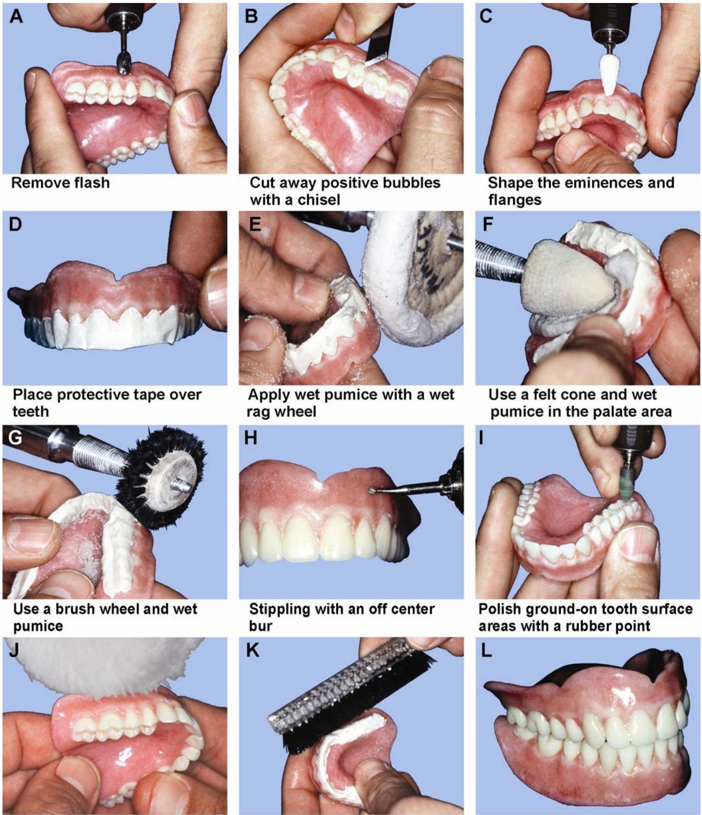
Apply polishing compound
Scrub the denture clean and place in an ultrasonic cleaner
Polish dentures
7.147.3. Once satisfied with the smoothness of the gingival trimming, move on to the palatal section of the maxillary denture. The construction of the brush wheel allows it toflex and conform to the intricate contours of the palate. If an anatomical palate has been placed in the denture, care must be taken to prevent elimination of the contours.
7.147.4. Aft er com pletion of the palate, proceed to the buccal surfaces of the maxillary, or mandibular dentures and the lingual flange secti ons of the mandibular denture. Begin by working from firm pressure to light pressure. A lot of pum icing should not be necessary if care was taken in the wax-up stage. Usually one pass over the eminences is sufficient.
7.147.5. Finish the bulk polishing of the denture base with a rag wheel running at low speed. Used properly, this wheel can reach al l flat surfaces located at the peripheral borders, deep lingual flanges, and the termination point of the maxillary denture at the post palatal seal.
7.147.6. Rinse the pumice from the dentures and insp ect them for scratches. If scratches are present, remove them with a rubber point and re peat the pum icing step in that area. When the smoothness of the resin is satisfactory, remove the tap e and p roceed with the f inal step in pumicing.
7.147.7. Often, denture teeth can be scratched or dulled as a result of shell blasting. Toremove the fine abrasions use asof t white b ristle brush wheel. Lightly pumice over the teeth and the entire denture, taking care not topolish away the surface anatomy of the teeth or the acrylic resin denture base.
7.147.8. Next, polish the denture with tripoli on a different set of wheels and brushes. At this stage, inspect the denture for scratches and irre gularities not visible during the pumice stage and repeat earlier steps of pum icing and polish with tripoli until the desired smoothness is attained. Remember that the success of each polishing s tep is determined by the step before it, so atten tion to detail is critical for complete success.
7.147.9. Complete the f inal polishing of the denture base using a soft, dry rag wheel im pregnated with commercial polishing compound and formulated for acrylic resin.
7.147.10. Use soap and water to scrub all polishing compound residue from the denture surfaces. Place the denture in a bag containing green soap and ammonia in an ultrasonic cleaning unit for 10 minutes.
¶ 7.148. Caring for Completed Dentures
To prevent the acrylic resin from drying and subsequently undergoing dimensional changes and warping, place the dentures into a m oist denture bag prior to delivery to the dentist. If mailing the dentures to another clinic, ship them in a plastic bag that contains asufficient amount of water to keep the dentures m oist. Addition of asuitable antimicrobial agent will prevent growth of bacteria or mold during shipment.
¶ 7.149. Troubleshooting Processed Acrylic Resin
Occasionally, dentures sho w defects. Commonerrors and their causes are as follows:
7.149.1. Excessive Denture Tooth Movement and Incisal Guide Openings. For denture tooth movement and incisal guide pin openings in excess of acceptable limits, the following errors (and causes) can occur:
7.149.1.1. Failing to achieve complete metal-to-metal contact when a flask is closed.
7.149.1.2. Using excessive packing pressure.
7.149.1.3. Using plaster instead of dental stone in the flasking procedure.
7.149.1.4. Placing additional resin in the mold after trial packing and before final closure.
7.149.2. Porosity. For porosity, the following errors (and causes) can occur:
7.149.2.1. Using insufficient pressure in the mold.
7.149.2.2. Packing the resin dough before it is ready.
7.149.2.3. Improper temperature and time control during curing.
7.149.2.4. Excess or insufficient monomer in the mix.
7.149.2.5. Acrylic thickness too great (inadequate contouring of the denture base)
7.149.2.6. Underpacking.
7.149.3. Fractured Teeth. For fractured denture teeth, the fo llowing errors (and causes) c an occur:
7.149.3.1. Using resin dough that was too stiff when it was packed.
7.149.3.2. Grinding porcelain denture teeth with a coarse stone wheel.
7.149.3.3. Applying packing pressure toorapidly.
7.149.3.4. Setting denture teeth in direct contact with the cast.
7.149.3.5. Inaccurate replacement of teeth that ha ve become dislodged during the boilout procedure.
7.149.3.6. Careless deflasking.
7.149.4. Grainy-Appearing Resin. For grainy-appearing resin, the following errors (and causes) can occur:
7.149.4.1. Using insufficient monomer to wet all of the powder.
7.149.4.2. Letting a packed case stand for a long period before curing.
7.149.5. Craze or Check Lines. The probable cause of craze or check lines in the acrylic resin is allowing the plastic to come into contact with a highly volatile so lvent such as acetone or chloroform.
7.149.6. Denture Base Streaks. For denture base streaks, the following errors (and causes) can occur:
7.149.6.1. Contamination with dirt and oils from bare hands.
7.149.6.2. Failure to stir the monomer-polymer mix thoroughly.
7.149.6.3. Using excess monomer.
7.149.6.4. Flaking of the tinfoil substitute.
7.149.6.5. Dry crusts of resinsomehow become incorporated into the mix.
7.149.6.6. Poor characterized denture base staining technique.
¶ Section 7AC — Maxillary Complete Denture Opposing a Natural Dentition
¶ 7.150. Overview
A maxillary denture opposing natural teeth requires changes to standard procedures in denture fabrication (Figure 7.133). The objective of this section is to identify those changes.
Figure 7.133. Maxillary Complete Denture Opposing a Natural Dentition.

¶ 7.151. Casts
It is a good idea to pour the teeth on the mandibular cast in a low f using metal to reduce wear and p ossible fracture of the cast’s surface. Iflow f using metal is not available, dental stone is adequate. (The use of a stone hardener is also an option if no low fusing metal is available.)
¶ 7.152. Mounting the Lower Cast
The dentist will pro vide a jaw relationship record with tooth indentations of cusp tips and incisal edges only. Trying to jam an oppos ing cast into a jaw relationship record that laps onto the facial and lingual surface of the teeth will lead to gr oss mounting inaccuracies. If arecord shows a lot more than cusp tips and incisal edges, take a razor-sharp blade and carefully trim back the record until nothing but cusp tip and incisal edge indentations remain. When a cast of natural teethis positioned against a jaw relationship record, it must be trimmed to see exactly where cusp tips and incisal edges are supposed to fit.
¶ 7.153. Denture Tooth Selection
Use plastic, cusped teeth to oppose natural teeth. Particularly in older individuals, natural teeth tend to be worn and have flattened o cclusal surfaces. Teeth with lower cusp angles, such as 20-degree teeth, may articulate better with worn, natural teeth.
¶ 7.154. Denture Tooth Arrangement
7.154.1. The occlusion scheme for dentures of this kind will be made with the mandatory multiple, well-distributed contacts in centric occlusion. Tooth contacts in lateral and protrusive excursions characteristic of a balanced denture are difficult to achieve. Therefore, dentist who wants more contacts should give specific directions.
7.154.2. Most dentists provide detailed instructions on how the anterior teeth are to be set. Arrange the teeth formaximum esthetic value. Incorporate an acceptable amount of vertical and horizontal overlap. Increasing the vertical overlap usually improves the app earance of an anterior tooth arrangement. It is also true that the chances for lateral and protrusive excursion balance tend to diminishas vertical overlap increas es. An “acc eptable” compromise needs to be drawn between these two considerations based on the dentist’s decisions.
7.154.3. When a denture is made to function agains t existing natural teeth, minor natural tooth irregularities usually prevent de velopment of the best possible centric occlusion. To compensate for inadequate or marginally adequate posterior tooth occlusion.
7.154.3.1. Open the occlusal vertical dimension about 1.0 mm on the articulator.
7.154.3.2. Set the posterior denture teeth in the best centric occlusion possible.
7.154.3.3. Surround the posterior teeth with enough wax to make them stable.
7.154.3.4. Clean any wax drippings from the occlusal surfaces.
7.154.3.5. Put the incisal guide pin back at its original setting. (This places the pin 1 mm off the guide table.)
7.154.3.6. Use a handpiece, tap ered 203 stone, and #6 ball diam ond to selectively grind the posterior teeth for the centric occlusion position until the pin meets the table.
¶ Section 7AD — Immediate Dentures
¶ 7.155. Overview
7.155.1. An i mmediate denture is constructed to com pletion before all of the natural teeth have been extracted. The denture is inserted “immediately” after the last extraction. Construction of an immediate denture can be started with any number of teeth present in an arch. More commonly, construction is begun with only anteri or teeth remaining in the affected arch. The usual practice is to extract all of the posterior teeth first and wa it about 6 weeks for heal ing. Generally speaking, if there are fewer teeth removed at the time of insertion, there are greater chances for success.
7.155.2. The principle behind immediate denture construction is that a cast of the patient’s mouth with its na tural teeth present is s culptured into ashape that represents the dentist’s best guess of what the residual ridge will look lik e after the teeth are extracted. The immediate denture is made on this modified, sculptured cast.
¶ 7.156. Advantages of Immediate Dentures
7.156.1. When making conventional complete dentures, it is best to wait at least 2 months after all the teeth have been removed before starting cons truction procedures. H owever, most patients are not willing to tolerate such an extended peri od of personal em barrassment. In the immediate denture treatment plan, the patient walks into a dental office with natural teeth that cannot be rehabilitated and walks out with a complete denture.
7.156.2. It is possible for the true occlusal vertical dimension to be reproduced exactly. However, when opposing natural teeth are not present at the start of a complete denture procedure, the occlusal vertical dimension has to be estimated.
7.156.3. From the standpoint of improved denture esthetics, a technician can re fer to a cast of the patient’s natural tooth arrangement for guidance.
7.156.4. When a denture base covers fresh extracti on sites, patients seem to experience less postoperative pain and healing progresses at a faster rate.
¶ 7.157. Disadvantages of Immediate Dentures
7.157.1. The cast on which an immediate denture is made is asculptured estimate of how the ridge is supposed to look after the extractions. The denture fits as well as the dentist’s guess.
7.157.2. The bone surrounding extraction sites can be e xpected to decrease in height and width (resorb)
Re sorption is usually the greatest in the first 2 months after the extractions have been performed. It slows down to a gradual rate of ch ange after a year’s time. An immediate denture will become unstable and require relining within 3 to 10 months.
¶ 7.158. Impressions and Casts
7.158.1. Tofabricate the preliminary impression and diagnostic cast, most dentists usealginate in a stock tray to make these impressions. The diagnostic cast is poured in the usual manner. The cast may be used to evaluate the patient’s condition, fabricate a custom t ray, and serve as a very valuable guide for selecting and arranging denture teeth. It is often advisable to pour the impression that will serve as the opposing cast during later fabrication steps in an improved dental stone. (The use of a commercially available stone hardener is also advisable.)
7.158.2. If the dentist is not com fortable with the first opposing cast made during the diagnostic impression appointment, then the opportunity tore take the impression will be available during the final impression appo intment. This saves the patient unavoidable delays in delivery of the immediate denture.
7.158.3. For a final impression, some dentists use a stock tray in combination with an elastic impression material; others use a custom tray. The tooth and tissue undercuts must be blocked out on the diagnostic cast and the custom tray adapted over them. As a rough guide, it takes at least 6 mm of relief for a tray to satisfactorily accommodate an elastic impression material. In any event, the impressions described so far are made by the dentist in one step.
7.158.4. There is a very popular method of making immediate denture impressions that requires two steps. First, a specialized cu stom tray is co nstructed to m atch outlines on the diagnostic cast drawn by the dentist. A tray of this type usually takes in all of the ed entulous areas. After the dentist makes the impression of the posterior edentulou s areas, he or she trims the excess and returns the impression to the patient’s mouth. Using a stock tray, the dentist makes an alg inate impression over the entire custom tray. The anterior teeth and soft tissue areas are recorded in the second impression, and the custom tray is removed from the mouthe mbedded in the second impression. The result is a highly accurate combination impression of the dental arch.
7.158.5. To make a master cast, follow these guide lines. if the final impression can be boxed, box it; if the impression cannot be boxed, pour it in two stages.
¶ 7.159. Selecting Denture Teeth
The dentist will designate the shade and mold of the denture teeth. The mold can be selected by using the stone teeth on the cast as a guide. Often, more than one mold is required. For example, a central incisor might be taken from one mold and a lateral incisor from another. Within the mechanical requirements of the prosthesis, every effort should be made to copy the arrangement of the patient’s own teeth. The dentist and the patient candecide on slight modifications to improve the appearance of the denture. Posterior teeth will be selected, using the considerations for conventional complete dentures (paragraph 7.60).
¶ 7.160. Record Bases, Occlusion Rims, and Articulator Mounting
The steps associated with making record bases and occlusion rims for immediate dentures are essen tially the same as those used for making conventional dentures (Secti ons 7G and 7H). The only differen ce is that the portions of the record base occupied by the na tural teeth are excluded (Figure 7.134-A). The upper cast is mounted according to anatomical averages or with a facebow transfer supplied by the dentist. The dentist will use record bases and occlusion rims to make a jaw relationship record, and the technician will use the record to mount the lower cast (Figures 7.134-B through -D).
¶ 7.161. Arranging Denture Teeth
7.161.1. Posterior Teeth. Posterior teeth are s et up on the record base, but anterior teeth are not (Figure 7.134-E). The posterior arrangement can be teste d in the patient’s mouth to check if important jaw relationships are correct. Most dentists do this routinely.
7.161.1.1. The dentist will choos e the occlusion scheme. Some of the possib ilities are predictable contact in centric occlusion only, balance in all excu rsions, or a monoplane occlusion scheme.
7.161.1.2. A maxillary immediate denture is usually opposed against natural lower teeth. This combination of circum stances is common. These cases are always constructed with cusped, plastic denture teeth. (F or an occlusion scheme, see paragraph 7.154.) After the posterior teeth are set, perform a basic, uncharacterized wax-up. The case is ready for a posterior tooth try-in if the dentist desires.
7.161.2. Anterior Teeth. If the patient’s natural anterior tooth arrangement is acceptable, try to copy it as closely as possible. The following steps provide guidance (Figure 7.134-F):
7.161.2.1. Mark the faciogingival and linguogingival junction betw een the tooth and the gum tissue with a pencil.
7.161.2.2. Draw a long axis line oneach stone tooth. Extend this line onto the facial surface of the cast as far as the labial sulcus.
7.161.2.3. Consequentively number alternate teeth on the cast. For example, number the left central incisor “1,” the right lateral incisor “2,” the left can ine “3,” the right central incisor “4,” the left lateral incisor “5,” and the right canine “6.”
7.161.2.4. With the incisal guide pin touching the table, draw a line on the labial surfaces of the mandibular anterior teeth that indicates the amount of maxillary incisor and canine vertical overlap.
7.161.2.5. Measure the distance between the labial surfaces of both canine with a Boley gauge. Record the measurement on the base of the cast.
7.161.2.6. Following the alternating tooth sequence as follows.
7.161.2.6.1. Use asaw or bur to cut down the middle of the tooth to the gingival pencil lines (Figure 7.134-G)
7.161.2.6.2. Remove the entire tooth down to the gingival lines, using a sharp knife and taking care to preserve the contours of adjacent stone teeth (Figure 7.134-H)
7.161.2.6.3. Excavate the facial root portion of the cast to a depth barely sufficient to accommodate the collar of a denture tooth (1.5 mmmaxi mum)
Reduce the collar if it is longer than 1.5 mm. Use a #4 round bur in a straight handpiece for the excavation.
Figure 7.134. Immediate Denture Fabrication.

7.161.2.6.4. Cut the lingual root portion of the cast flush with the linguog ingival pencil line (Figure 7.135)
7.161.2.7. After cuttin g away a stone tooth on the cast, position the correspond ing tooth as shown in Figure 7.136-A and -B and as follows.
7.161.2.7.1. Use the contact areas and contours of the adjoining stone teeth to guide the mesiodistal and faciolingual placement of each denture tooth.
7.161.2.7.2. Use the line scribed on the facial surface of the lower anteriors as a check on the vertical overlap.
7.161.2.7.3. Use the pencil lines that extend into the labial sulci as aids in aligning the long axes of the replacement teeth.
7.161.2.7.4. Have a separate cast of the patient’s natural tooth arrangement available for periodic reference. Use the diagnostic cast or make a duplicate of the master cast.
7.161.2.7.5. After the canine teeth are set, check to see that the distance between their labial surfaces is the same as the original distance between the stone canines.
Figure 7.135. Excavation for Seating Denture Toothin Immediate Denture Cases.

¶ 7.162. Performing a Final Wax-Up
The final waxing and contouring of an immediate denture differs from a conventional denture in the following respects (Figure 7.136-C):
7.162.1. The palatal portion of the record base is not sawed out in a maxillary immediate denture final waxing procedure. Ensure the baseplate used for the posterior teeth try-in is nothicker than 2 to 3 mm.
7.162.2. The labial flange areas of an immediate denture require special attention. If thick, bulky flanges are made to cover bony areas where virtually noresorption has occurred, the patient’s lips will appear ballooned and distorted. If the resin is tooth in, the flanges will fractu re. Follow these suggestions for the labial flange areas of an immediate denture:
7.162.2.1. Fill the sulcu s rolls with wax and co ntour the wax at the necks of the teeth in the usual manner.
7.162.2.2. Make the depth of wax between the sulcus rolls and the gingival contouring equal to one thickness of 28-gauge wax plus one thickness of baseplate wax.
7.162.2.3. Do not try to produce deep festooning. Instead, be content with surface irregularities resulting from the sheet wax following natural curvatures.
7.162.2.4. Stippling of the denture base for immediate dentures is not recommended. However, if stippling is used, be sure it is the positive, blow-on variety.
7.162.3. Be certain the teeth are in good centric occlusion and the incisal guide pin is touching the incisal guide table.
¶ 7.163. Flasking, Wax Elimination, Packing, Processing, and Finishing
Follow ordinary flasking and boilout practices. After the wax is eliminated, perform all of the following procedures that apply:
7.163.1. If the posterior palatal seal has not been cut into the cast, do it now (paragraph 7.101.1.2)
7.163.2. Imagine how the residual ridge will look after the natural teeth are extracted. After the wax is eliminated, wait until the flask is cool enough to handle (Figure 7.136-D). At this time, the dentist will trim off the faciogingival stone ledges and otherwise modify the cast according to an estimate of alveolar bone contours after the remaining natural teeth are removed. To do this, the dentist will usually draw a line on the cast, attempting torepresent where the depth of the gingival sulcus can be found around each natural tooth. After cutting off the stone ledges, the dentist blends the contours of the cast into the pencil line (Figures 7.136-E and 7.137).
Figure 7.136. Immediate Denture Fabrication (Denture Tooth Setup and Preprocessing Cast Corrections).

Set up alternate anterior

Anterior set up completed

Final wax up

Wax eliminated from the mold

Dentist trims the ridge area

Completed immediate denture
Figure 7.137. Trimming the Cast After Boilout.

7.163.3. After the dentist finishes trimming the case, he or she may ord er a transparent surgical template. This template may be accomplished by two methods:
7.163.3.1. Vacuum Formed (Omnivac®) Method. Take a sheet of clear plastic tray material and suck it down over the cast and the half flask. Cut away the excess plastic tray material.
7.163.3.2. Compression-Molded Method.
7.163.3.2.1. After the dentist trims the cast, make an alginate impression of the cast using a rim-lock tray. Pour a stone cast from this impression. Adapt two layers of pink baseplate wax to the duplicate cast for constructing a clear, surgical template.
7.163.3.2.2. Flask this cast in the us ual manner. Eliminate the wax. Apply tinfoil sub stitute to the mold surfaces and to the surface of the cast. Pack and process using clear acrylic resin.
7.163.3.2.3. Finish and polish the template. The tissue surface of the templa te is used as a guide for surgically shaping the ridgeto conform to the tissue surface of the denture. The principle behind the template is that skin over bony areas is com pressed between the bone and the transparent plastic. L ooking through the plastic, these com pression areas appear white in contrast to the reddish coloration of the surrounding tissue.
7.163.4. Pack, cure, and deflask the immediate denture. Restore the denture’s occlusal vertical dimension. Finish and polish the denture (Figure 7.136-F).
¶ Section 7AE — Cast Metal Denture Bases
¶ 7.164. Overview
The cast metal basedenture is usually made of either chrome or an aluminum alloy. It is adaptable to either an upper or a lower denture.
¶ 7.165. Advantages of Cast Metal Denture Bases
There are advan tages to using cast metal bases. Metal bases are prim arily used in patients who c ontinually fracture their dentures during a normal function. The strength factor allows the denture to be made much thinner across the palate. As a result, thequality of the patient’s speech improves. Mouth tissue tolerates chrome and alum inum alloy well. Metal bases generally fit tissue con tours more accurately than processed resin. Metal is a much better conductor of temperature than acrylic resin, and many patients claim better taste sensations as a result. If a metal base is intentionally made to be heavy, the sheer weighthelps keep the lower denture in place.
¶ 7.166. Disadvantages of Cast Metal Denture Bases
There are also disadvantag es to using cast metal bases. Cast metal denture bases are more time-consuming to make and difficult toreline. All borders of
the denture that are made of metal must be accurately placed relative to limiting structuresin the mouth because metal borders are difficult to adjust.
¶ 7.167. Metal Denture Base Designs
There are two basic designs formetal denture bases. In the first design, all denture bearing areas as well as all denture borders are covered in metal (Figure 7.138-A). (Note the retention beads and finish lines.) The second design is a combination of metal and resin coverage. Metal reinforces only thos e critical areas of the denture base subject to fracture; processed resin accounts for the rest (Figure 7.138-B). The dentist chooses the design.
¶ 7.168. Combination Resin and Metal Maxillary Denture Base
Metal forms the palatal and posterior palatal seal portions of the denture and the rest is resin (Figure 7.138-B). To construct this denture base, perform the following:
7.168.1. Read the instructions for relief, duplic ation, waxing, casting, and finishing metal frameworks described in Chapter 8. Remember the following very important steps:
7.168.1.1. Relieve areas under acrylic resin retention grids before master cast duplication so the grid can properly anchor the resin.
7.168.1.2. Incorporate distinct internal and external finish lines into the wax-up so the resin meets the cast framework in a butt joint.
Figure 7.138. Cast Metal Denture Bases.

7.168.2. If the posterior palatal sea l is to be in metal, it is the respon sibility of the dentist to establish the boundaries of this area on the cast. Make sure the posterior palatal seal has been cut into the cast. Following the dentist’s design on the diagnostic cast, block out the labial and buccal undercuts, and seal the relief wax to the master cast in the appropriate areas. Make sure the palatal border of the relief wax is strai ght and well defined because it forms the finish line for the acry lic resin on the tissue side of the denture.
7.168.3. Duplicate the master cast in investment.
7.168.4. Adapt a 26-gauge stipple sheet to the palate. Add aretention grid over the relief areas of the investment cast (Figure 7.139). Seal them together and to the cast.
Figure 7.139. Cast Metal Denture Base (Wax Pattern).

7.168.5. Make the external finish line with 14-gauge half-round wax and sprue the pattern.
7.168.6. Coat the pattern with a w etting agent. Apply the “paint-on” layer of investment in a uniform 3 mm thickness.
7.168.7. After the paint-on layer of investment hardens, mix the outer investment and fill the flask. Submergethe pattern and cast in the flask. When the investment hardens, eliminate the wax and make the casting.
7.168.8. Finish and polish the casting.
7.168.9. The finished metal base must be accurately seated on the master cast. Continue with the denture tooth setup in the conventional manner. NOTE: The details of waxing a pattern and casting a metal palate are in Chapter 8 of this volume.
¶ Section 7AF — Tooth-Supported Dentures (or Overdentures)
¶ 7.169. Overview
Occasionally, teeth purposely cut down close to the level of the g um line are left in the alveolar bone to reduce the rate of ridge resorp tion. When a denture is made to fit “over” these remaining teeth, the denture assumes the nam e overdenture (or tooth-supported denture). The dentist may choose toretain from one tofive teeth as overdenture abutments. Most commonly two abutm ents are chosen. The decision to save teeth as overdenture a butments is based on their periodontal health, decay, potential for endodontic treatment, and their position in the dental arch. From a technical point of view, there is very little that is unusual ab out these dentures. The difficulties associated with overdentures arise due to the space limitations caused by the presence of abutment teeth.
¶ 7.170. Increasing Denture Base Strength
Tooth-supported dentures (overdentures) often need strengthening to prevent fracturing the denture base, specifically in the area of the abutm ent teeth. This can be done by selecting a high impact resin using al ternative packing techniques or by making a cast metal base.
7.170.1. High Impact Resin. Using Lucitone 199 ® (by L.D. Caulk Co., Milford DE) or a n alternative high impact resin is believed to create astronger denture base. Follow the manufacturer’s directions for polymer to monomer ratios and for curing procedures. NOTE: Even though the manufacturer states that Lucitone 199 acrylic does not need to be trial packed, standardized trial packing procedures generally yield more consistent results (paragraph 7.117).
7.170.2. Alternative Packing Techniques. Alternative packing techniques may also be utilized. Improving the bonding between the denture base acrylic resin and the teeth can strengthen the denture base. The bonding surface area and chemical attachment are improved when the ridge laps of the teeth are prepared prior to packing. Prepare the posterior teeth by cutting dovetailed grooves approximately 2 mm wide and 2 mm d eep. Do not cut groo ves into the anterior teeth because this may affect the shade of theseteeth. Instead, drill shallow holes with a round or inverted cone bur on the ridge laps of the anterior teeth. Also, lightly roughen the pol ished ridge lap surface of the anterior teeth to remove the “glaze” layer. After completing the tooth preparations, carefully clean all deb ris from the mold, apply a tin f oil substitute to the mold, remove any tin f oil substitute applied to the teeth, and continue packing procedures.
7.170.3. Cast Metal Bases. Cast metal bases can also be u sed to increase denture base strength. Strengthis the basic purpose for making cast metal bases for a tooth-supported denture. Cast metal basedesigns are quite different from the one depicted in Figure 7.138 for complete dentures. Coverage is usually restricted to the cres t of the alveo lar ridge. Also, these bases are normally made to be completely covered with acryli c, showing no exposed metal surfaces (paragraph 7.171). Cast metal bases can be grouped into two cat egories; full arch bases and m inibases, as follows:
7.170.3.1. Full Arch Bases. This design consists of a cros s arch casting using the anterior abutments bilaterally and including distal extensions toposterior abutments or residual ridges or both. In the maxillary arch, f ull palatal coverage or a palatal s trap is added to incre ase rigidity.
7.170.3.2. Minibases. These small unit castings may be individual covers for abutment teeth or they may be united to incre ase c ross arch str ength. Min ibases are a lways limited to the immediate areas of the abutment teeth.
¶ 7.171. Fabricating Cast Metal Bases
Cast metal bases for tooth-supported dentures are made of chrome alloys. Full arch castings can be made by using the partial denture framework fabrication sequence in Chapter 8. On the other hand, some m inibases may be small enough to be constructed by using the procedures for making base metal fixed fr amework castings. This fabr ication sequence is as follows:
7.171.1. Survey the case and mark undesirable undercuts.
7.171.2. Block out the gingival crevice around indi vidual abutm ent teeth and tissue undercuts. (Relief wax will not nor mally be needed unless the framework design includes open retention for acrylic resin.)
7.171.3. Prepare the master cast for spruing and duplicate it in investment.
7.171.4. Transfer the design from the master cast to the refractory cast.
7.171.5. Adapt a layer of 24-gauge sheet-casting wax to the refractory cast and trim to the outline scribed earlier. Seal the casting wax to the cast and lightly flame the pattern. Apply tacky liquid to the wax and sprinkle tiny retention beads on the surface. Two small 18-gauge wax wire hand les can also be added in the posterior area for the dentist’s useduring jaw relation procedures. NOTE: On larger metal bases, use 22-gauge wax; on smaller ones, use 26-gauge wax.
7.171.6. Sprue, invest, and cast in the usual manner.
7.171.7. Desprue the casting and trim the borders of the casting to the desired extensions in a perpendicular direction to the cast surface. Finish the axial walls of the abutment indentations with a fine stone.
7.171.8. Sandblast, electro-polish, rubber, and po lish the casting. Avoid excessive polishing of tissue-bearing surfaces.
7.171.9. Fit the framework to the cast. Grind on any areas that prevent seating and then repolish them.
7.171.10. Note that the cast metal base may need to be opaqued and will probably need to be cemented to the cast prior to pack ing. Opaquing the retention side of the metal base with a pink opaque (for example, Synfony) is not usually a consideration unless there is a possibility of metal showing through a thin denture base. The dentist may ask that the casting be opaqued if conditions warrant it.
7.171.11. Lastly, the cast metal base must be cem ented to the cast toprev ent dislodgment during packing. This is especially important with m inibases because they may not have any bracing qualities at all. A thin mix of zinc phosphate cem ent is used to hold the metal base in place. Cyanoacrylate cement or Zap-It may also be used.
7.171.12. After the cem ent has set, remove any excess. The denture can now be packed and completed in a normal manner.
¶ 7.172. Tooth-Supported Dentures With Retentive Attachments
This entirely special area of denture technology will not be discussed h ere. However, for an authoritative reference, s ee Brewer, A.A. and Morrow, R.M., Overdentures, St. Louis, L.V., Mosby Co.
¶ Section 7AG — Acrylic Denture Tooth Repairs
¶ 7.173. Tooth Repair Possibilities
There are at least two categories of denture tooth repair as follows:
7.173.1. The first category of denture tooth repair is when the colla r area of the denture base (to include the facial and proxim al plastic su rrounding the af fected tooth) is still in tact. It is not necessary to alter the collar area of the denture base to perform the repair.
7.173.1.1. Reattach the original tooth if it is still salvageab le. Sometimes a porcelain or plastic tooth may pop out of its seat in a denture base without damaging the base.
7.173.1.2. Replace a lost or broken tooth with a duplic ate that has the exact collar and proximal shape. This is only possible if the collar and pr oximal contours of the or iginal tooth were not modified in any way and there is a duplicate handy.
7.173.2. The second category of denture tooth repair is when the collar area of the denture base (to include the facial and proxim al plastic surrounding the tooth) must be altered to perform the repair.
7.173.2.1. The following possibilities may exist. the facial plastic of the denture base is still intact, the original denture tooth is lost or br oken, or the shape of the available replacement tooth does not conform to the shape of the original “seat.”
7.173.2.2. In almost all repairs involving a plastic tooth, the original “seat” for the tooth is destroyed. A broken acrylic tooth must be completely drilled out before performing arepair. Plastic teeth that are accidentally knocked out us ually carry some of the attached denture base with them.
¶ 7.174. Repair Procedures
Repair procedures are shown in Figure 7.140 and as follows:
7.174.1. Removing the Broken or Loose Tooth From the Denture Base. If a porcelaintooth is loose or broken, but it is still em bedded in the denture base, free any mechan ical retention (pins, diatoric) by cutting away the denture base material from the lingual surface. Do not cut through to the facial. P op the denture tooth loose. The toot h should easily and accura tely go back to its original position. In the case of an acrylic tooth, the only choice is to cut or grind the tooth out down to the denture base material.
7.174.2. Selecting a Replacement Tooth. If a new tooth is used, obtain the mold number of the original tooth, indicating size and sh ape, from the imprint of the ridgelap in the denture base. If this information is not available, select a replacement based on the apparent mold of the rest of the setup. Determine the shade from the adjacent teeth with the aid of a shade guide.
7.174.3. Preparing the Repair Site. Differences in preparation depend on whether the facial resin of the denture base is affected or not, as follows:
7.174.3.1. If the facial denture base resin is not affected.
7.174.3.1.1. Roughen the ridgelap of acrylic teeth to guarant ee good chemical bonding with the repair material. Cut a small diatoric into a plastic tooth as additional retention.
7.174.3.1.2. Make a “box” preparation in the denture base lingual to the tooth to be repaired (Figure 7.140-A)
7.174.3.1.3. Position the tooth in its seat and stick y-wax it in place from the lingual (Figure 7.140-B)
7.174.3.1.4. Construct a labial matrix to hold the tooth in position during repair (Figure 7.140-C)
7.174.3.1.5. Remove the sticky wax after the stone is set (Figure 7.140-D)
7.174.3.1.6. Paint the matrix with a tinfoil substitute.
7.174.3.1.7. Reassemble the denture, tooth, and matrix in correct alignment (Figure 7.140-E)
7.174.3.1.8. Sticky-wax the tooth to the matrix and the matrix to the denture.
7.174.3.2. If facial denture base resin is not or cannot be left intact.
7.174.3.2.1. Position the tooth by grinding either the denture base or the tooth, as required. Since denture base references for position ing a replacement tooth are un reliable, use a cast of the opposing natural teeth or opposing denture for positional reference. Sticky wax the replacement tooth in place from the lingual.
7.174.3.2.2. Reconstruct the missing facial denture base plastic in white (Ivory) wax.
7.174.3.2.3. Make a facial matrix. During the progre ss of the repair, it holds the tooth in position and shapes the facial surface of the denture base.
7.174.3.2.4. Paint the matrix with a tinfoil substitute.
7.174.3.2.5. Remove all the wax from the teeth and denture base. Roughen the ridgelap area of resin replacement teeth. Cut a small diatoric into a plastic tooth as additional retention insurance.
7.174.3.2.6. Lingual to the tooth to be repaired, make a box preparation in the denture base. Create butt joints between the denture base and the repair material where possible.
Figure 7.140. Denture Tooth Repair.

Make a box presentation

Position the replacement tooth
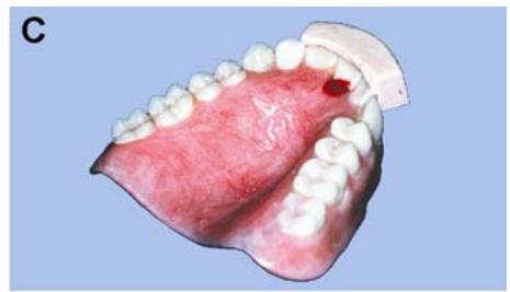
Construct a labial matrix

Clean all wax from repair site

Reassemble the tooth, matrix, and denture

Apply monomer

Sprinkle polymer

Remove excess resin from lingual of tooth

Remove excess resin from facial of tooth

Cure in a pressure pot

Finish and polish denture repair
7.174.3.2.7. Reassemble the denture, the tooth, and the matrix in proper alignment.
7.174.3.2.8. Sticky wax the tooth to the matrix. Attach the matrix to the denture with sticky wax in two or three widely separated places.
7.174.4. Adding the Autopolymerizing Repair Resin.
7.174.4.1. Moisten the repair area with monomer (Figure 7.140-F) and sprinkle with a layer of polymer (Figure 7.140-G)
Alternate the polymer and monomer until the repair resin is built up slightly higher than the su rrounding denture base. Using a small brush moistened with monomer, remove any excess acrylic from the lingual and facial of the denture tooth (Figure 7.140-H and -I).
7.174.4.2. Let the resin cure in a pressure pot according to the manufacturer’s direction s (Figure 7.140-J) Immersion of the repair in water retards monomer evaporation; while warm water speeds up resin polymerization. In the absence of directions, hold water temperature to about 110 oF in the pot at a depth deep enough to cover the repair. Secure the lid to the pot and apply a minimum 15 lb/in of air pressure for 10 minutes. Air pressure reduces bubble size and makes the resin denser.
7.174.5. Finishing and Polishing the Repair. Use conventional finishing and polishing procedures to blend the repaired area to the existing denture base (Figure 7.140-K).
¶ Section 7AH — Acrylic Denture Base Repair
¶ 7.175. Causes of Denture Breakage
Very often an already existing weakness or fault in the prosthesis causes the breakage of the denture itse lf; and, unless this fault is rem edied at the time of the repair, it may soon break again from the same cause.
7.175.1. The dentist must make every effort to see that causes such as faulty occlusion, poor fit due to mouth changes, or careless handling by the patient are corrected before proceeding with the repair.
7.175.2. Before the introduction of the self-curing resins, most acrylic resin repairs were done by flasking. This frequently resulted in warpage of the denture base caused by arelease of strains in the original resin at curing temperature. The self-curing acrylic resins eliminate this hazard and are recommended for virtually all repair procedures.
¶ 7.176. Conditions for Success in any Repair Procedure
For a denture base repair to have a chance to be successful, the parts must be perfectly clean, assembled with to tal accuracy, and kept ab solutely immobile while the repair resin cures.
¶ 7.177. Types of Denture Base Fractures
7.177.1. Simple. In this type offracture, the denture has usually been broken intopieces, and there is absolutely no doubt about how the pieces fit together. The patient’s pres ence and clinical cooperation are not necessary. (See paragraph 7.178 for repair procedures.)
7.177.2. Complex. In this type offracture, the pieces cannot be made to fit againstone another in precise relationships, and sometimes one or more fragments have been lost (for example, loss of a flange). The pieces can be realig ned or new resin adde d only if the dentist assis ts in the reconstruction and the patient is present. (See paragraph 7.179 for repair procedures.)
¶ 7.178. Repair Procedures for Simple Denture Base Fractures
7.178.1. Assemble the parts of the denture. Apply s ticky wax to the fracture line to maintain the pieces in correct apposition. It is a definite advantageto have a helper when joining the pieces.
7.178.2. Attach two or more old burs or pieces of co at hangar wire acro ss the fractu reline of the denture toreinforce the denture until the matrix is made (Figure 7.141-A). Do not use wooden sticks, as wood tends to warp.
7.178.3. Block out all tissue surface areas outside the repair area with w et tissue or other suitable material (Figure 7.141-B)
Pour a cast of the denture to include generous areas oneither side of the fracture line and on all denture borders (Figure 7.141-C). After the stone sets, remove the denture from the cast and trim the borders.
Figure 7.141. Denture Base Fracture Repair (Sprinkle-On Method).

7.178.4. Prepare the cast. Soak the cast in SDS to remove the air. Blow off the excess moisture. Apply a tinfoil substitute to the cast at least 8 mm beyond the denture fracture line in all directions (Figure 7.141-D). Allow the tinfoil substitute to dry.
7.178.5. Rabbet and bevel the edges of the fracture line on the pieces to be joined to increasethe amount of bonding area between the old and new acrylic resin (Figure 7.141-E)
7.178.6. Rabbet along the edge of each fragment. Cu t a rabbet ch annel 3 to 4 mm wide and
halfway through to the tissue surface of the denture. (The total width of the groove on the polished side of the denture should equal 6 to 8 mm.)
7.178.7. Bevel along the edge of each fragment. Straighten and smooth the edges of the fragments with an arbor band. Bevel the fractu reline so there is 2 mm of space on the tissue side and 3 mm of space on the polished surface side.
7.178.8. Replace the denture fragments on the cast in perf ect alignment. Tack the fragments down with sticky wax (Figure 7.141-F).
7.178.9. Add the repair resin, using either the dough method or the sprinkle method. Use autopolymerizing resin with both systems.
7.178.9.1. Dough Method.
7.178.9.1.1. When using the dough method, first soak tissue paper in warm water to form a soft pulp. Pack the pulp into the preparation and contour it to the desired shape. Prepare lingual and facial matrices that cover the tissue. (Before making the matrices, paint a separating medium onto the cast surfaces that come in contact with fluid plaster.)
7.178.9.1.2. Remove the hardened matrices and we t tissue from the cast. Paint each matrix with tinfoil substitute. Mix se lf-curing resin according to the manufacturer’s directions and let it reach packing consistency.
7.178.9.1.3. Lightly moisten the repair area with monomer and press the doughy acrylic resin into the repair area. Put the matrices in place and hold with a rubber band. Place the assembly in a pressure pot and cure according to manufacturer’s directions.
7.178.9.2. Sprinkle Method. To use the sprinkle method, start by moistening the repair site with self-curing resin monomer (Figure 7.141-G). Sprinkle a layer of polymer over the desired area (Figure 7.141-H). Apply the monomer and polymer alternately until the material is built up to overfill the preparation slightly. (Overbuilding allows the finishing procedures after the resin cures.) Let the buildup stand for a few minutes until the sheen disappears from the surface (Figure 7.141-I). Place the assembly in a pressure pot.
7.178.10. Let the resin cure in a pressure pot according to the manufacturer’s directions (Figure 7.141-J)
Immersion of the repair in water retards monomer evaporation; warm water speeds up resin polymerization. In the absence of directions, hold water at about 110 oF in the pot at a depth deep enough to cover the repair. Secure the lid to the pot and apply a minimum 15 lb/in of air pressure for 10 minutes. Air pressure reduces bubble size and makes the resin denser.
7.178.11. Recover the repair and finishing. Release the pressure from the pot. Carefully remove the repaired denture from the cast. Trim the new material so it is even with the old acrylic resin (Figure 7.141-K). Assuming it already has the proper thickness, trim the old material no more than is necessary. Finish and polish the denture in the usual manner (Figure 7.141-L).
¶ 7.179. Repair Procedure for Complex Denture Base Fractures
In this type of repair, the most likely problem is that a piece of the denture is missing and must be replaced. Patients routinely fracture a denture flange and lose the fragment. The dentist will use a material-like modeling plastic, add it to the denture’s fracture line, place the denture in the patient’s mouth, and shape a new section for the lost piece of the denture. The technician will receive a denture with a replacement area made from modeling plastic. The modeling plastic will be converted into resin, using the following sequence:
7.179.1. Use wet paper towels or wet tissue to pack undercut areas not involved in the repair. Pour a cast that includes all denture borders and the tissue surface of the modeling plastic section, plus an additional 8 mm of denture tissue surface.
7.179.2. After the stone is set, remove the denture from the cast. Cut the modeling plastic away from the denture and bevel the denture’s broken margin. Paint tinfoil substitute onto the cast to take in all of the repair area and 8 mm beyond.
7.179.3. Replace the denture on the cast and tack it down with sticky wax.
7.179.4. Repair the denture by the dough or sprinkle method.
7.179.5. Finish and polish the denture.
¶ Section 7AI — Relining a Complete Denture
¶ 7.180. Resurfacing the Tissue Side of a Denture
7.180.1. A reline is the resurfacing of the tissue side of a denture, using new base material to make the denture fit more accurately.
7.180.2. The reline can represent a solution to two problems, and one or both problems can exist at the same time. The first problem is a denture that is unstable on the residual ridge. The second problem is that a patient’s occlusal vertical dimension is showing progressive overclosure because of generalized denture tooth wear or ridge resorption.
7.180.3. There are a number of acceptable ways to perform a reline. Two methods are described in this chapter; the jig method (paragraph 7.182) and the flask method (paragraph 7.183).
¶ 7.181. Clinical Procedures
In the clinical part of the reline procedure, the dentist must first modify the denture by grinding out tissue surface undercuts and uniformly reducing the flanges about 2 mm. Using the denture as a custom tray, the dentist will make a new impression on the arch. The patient will hold the teeth in centric occlusion and the mandible in centric relation while the impression material is setting. This combined denture impression-jaw relationship record will be delivered to the dental laboratory (Figure 7.142-B).
¶ 7.182. Jig Method
The following procedures are included in the jig method:
7.182.1. Cast Fabrication. Box and pour the impression. Use equal parts plaster and pumice to box elastic impression materials. Use conventional wax beading and boxing for zinc oxide-eugenol impressions (Figure 7.142-C). After the cast is poured, trim it (Figure 7.142-D) and cut index notches in the base (Figure 7.142-E). Do not remove the denture from the cast at this time.
7.182.2. Mounting the Assembly in the Jig (Mandibular Denture)
7.182.2.1. Start by shaping a dental stone patty on the bottom half of the jig. Gently press the occlusal surfaces and incisal edges into the mix. Do not sink the denture past the greatest diameters of the teeth. Get a decent imprint of occlusal surfaces and incisal edges. After the stone sets, it should be possible to pull the denture out of the tooth indentations without difficulty.
7.182.2.2. Assemble the jig. Tighten the locknuts and make certain the shoulders of the upper half fit flush on the posts in metal-to-metal contact. Make sure the denture teeth are perfectly seated in the index and tack the teeth to the dental stone with sticky wax.
7.182.2.3. Remove the upper half of the jig to attach the cast to the jig. Apply dental stone to the base of the cast being sure to fill the index notches. Replace the upper half of the jig and tighten the locknuts. Make certain the upper half jig is making metal to metal contact with the posts and the undercut hole in the upper half is filled in completely.
Figure 7.142. Jig Relining of a Maxillary Complete Denture.

Figure 7.142. Continued.

Remove impression material from denture base

Create a butt joint on denture's peripheral border

Mix and apply resin to the undercut areas on the cast

Apply remaining resin to the denture base

Reassemble the jig

Mold resin around the borders

Cure the reline in a pressure pot

Recover, finish, and polish the denture
7.182.3. Mounting the Assembly in the Jig (Maxillary Denture)
7.182.3.1. A maxillary denture uses a slightly different treatment. Make sure the vault of the denture is supported against forces generated during the packing phase of the reline procedure. Block out all undercuts on the linguogingival surfaces of the teeth and the palatal surface of the denture using a color of material that contrasts against white and pink (Figure 7.142-F).
7.182.3.2. Form a dental stone mound on the bottom half of the jig. Fill the palatal vault of the denture with stone up to the level of the teeth (Figure 7.142-G). Center the denture on the patty without burying the facial surfaces of the teeth (Figure 7.142-H).
7.182.3.3. After the stone sets, take the denture off the index and remove every trace of blockout wax. Seat the denture back in the index and sticky-wax it down. Attach the cast to the upper half of the jig in the same manner described for the mandibular denture (Figure 7.142-I).
7.182.4. Preparing the Cast.
7.182.4.1. Remove the locknuts and lift the denture from the occlusal index. Carefully separate the denture from the cast (Figure 7.142-J). Do not break the denture or the cast. The retromylohyoid area of a mandibular denture’s lingual flange has the most potential for being severely undercut. If the mandibular denture cannot be removed from its cast because of such an undercut, cut off the specific part of the lingual flange. When removing an undercut flange, the cut extends through the plastic to the impression material. Be careful not to cut into the cast.
7.182.4.2. When dealing with a maxillary denture, ask the dentist to cut the posterior palatal seal (Figure 7.142-K)
7.182.4.3. Soak the cast in lukewarm SDS for 5 minutes. Flush the cast with hot water.
7.182.4.4. Paint the cast with a tinfoil substitute and let it cool (Figure 7.142-L)
7.182.5. Preparing the Denture.
7.182.5.1. Grind out the impression material from the denture (Figure 7.142-M)
7.182.5.2. If the dentist hasn’t already done it, relieve all undercuts on the tissue surface of the denture and create a butt joint at the flange borders (Figure 7.142-N)
7.182.5.3. Uniformly roughen the entire tissue surface of the denture. This helps improve the bond between the denture base and the new resin.
7.182.6. Mixing and Applying the Resin.
7.182.6.1. Use a ratio of two parts self-curing resin powder to one part liquid. The fluid consistency this ratio produces is essential for minimum entrapment of air and good bonding with the denture base material.
7.182.6.2. Put the liquid in a glass jar and slowly add the powder. Swirl the jar until the powder is saturated. Use a spatula to spread the resin around the buccal and labial sulci of the cast. Be sure to fill all undercuts with resin (Figure 7.142-O). Push the resin ahead of the spatula, being careful not to trap the air.
7.182.6.3. So far, the tissue surface of the denture base has been roughened to improve the bond between the new resin and the denture base. To enhance that bond even further, paint the tissue surface of the denture with monomer. Then spread the remainder of the fluid resin onto the tissue side of the denture (Figure 7.142-P).
7.182.7. Packing the Denture: (NOTE: Always wear disposable gloves when handling acrylic resin.)
7.182.7.1. First, allow the remaining resin to gel until it no longer runs freely. Place the denture into the tooth index on the bottom half of the jig (Figure 7.142-Q). Attach the top plate of the jig with thumbnuts and close it just short (about 2 mm) of the metal-to-metal contact. Use a moistened-gloved finger or cotton tip applicator to push the resin back between the denture and the cast (Figure 7.142-R).
7.182.7.2. Wait until the resin is doughy and firm. Premature jig closure could result in a porous reline. Tighten the thumbnuts, alternating sides, until there is metal-to-metal contact between the top plate and the shoulders of the posts. Metal-to-metal contact must be achieved.
7.182.8. Curing the Denture. Cure the denture in a pressure pot with lukewarm water (110 oF). Apply a minimum of 15 lb/in2 for at least 10 minutes (Figure 7.142-S)
7.182.9. Finishing and Polishing the Denture. Finish and polish the relined denture using procedures for complete dentures (Figure 7.142-T).
¶ 7.183. Flask Method
7.183.1. Cast Fabrication. Box and pour the denture containing the impression in artificial stone in the same manner as the jig method, except no index notches are required. Flask the denture the same way as in complete denture techniques (paragraph 7.104).
7.183.2. Separating the Flask Halves. To soften the impression material, place the flask in boiling water for 4 minutes. Remove the flask from the water and open the flask.
7.183.3. Preparing the Cast. Flush the debris from the cast and let the flask halves cool down. Give the cast to the dentist for placement of the posterior palatal seal. On return, paint tinfoil substitute onto the cast surface and let it dry.
7.183.4. Preparing the Denture. Grind out all remaining impression material and uniformly roughen the tissue surface of the denture with an acrylic bur.
7.183.5. Packing and Curing. Use self-curing resin as the reline material; with its use, there is less danger of warping the denture base. Be sure the mold is cold before packing. Mix the acrylic resin according to the manufacturer’s instructions. Moisten the tissue side of the denture base with monomer and place the new resin in the mold. There is a relatively short working time with self-curing resins, so work efficiently to ensure at least one trial pack. Bench cure the resin in the flask press for 1 hour.
7.183.6. Deflasking, Finishing, and Polishing. Use the commonly accepted procedures for complete dentures.
¶ Section 7AJ — Rebasing (Duplicating) a Denture Base
¶ 7.184. What is Rebasing?
Rebasing a denture involves refitting the denture using a corrective impression (as in a reline) and replacing all the denture base material with new acrylic resin. It can be done for those dentures whose base material is discolored after being used for years or for dentures that have been repaired several times
7.184.1. Rebasing is not done frequently because acrylic teeth in most old dentures show advanced wear and are not serviceable. However, rebasing an old denture is a great deal quicker than making a new one. Rebasing is the treatment of choice when the time factor is important or when the teeth are in good condition. A rebased denture serves as the perfect temporary prosthesis while a new denture is being made.
7.184.2. Because the denture base material is completely removed in rebasing, there must be a means of maintaining the relationship of the teeth to each other and to the ridge while the denture teeth are without support. Articulators were extensively used for this purpose, but their parts occasionally move or bend. The best option is to use a rigid relining jig. The procedures associated with using the reline jig are in paragraph 7.185.
¶ 7.185. Procedures for Using a Reline Jig
7.185.1. Cast Fabrication. After the dentist makes the impression as described for a reline (paragraph 7.181), box and pour the impression. After the artificial stone has set, trim the cast and index the base. Replace the missing or broken teeth and wax them in position.
7.185.2. Mounting the Assembly in the Jig. Follow the procedures outlined in paragraphs 7.182.2 and 7.182.3.
7.185.3. Recovering the Denture Teeth. Remove the denture from the cast and then separate the teeth from the denture base as follows:
7.185.3.1. Removing Porcelain Teeth. Heat the teeth and adjacent acrylic resin slowly with an alcohol torch. (Rapid heating will cause the teeth to crack.) To distribute the heat more evenly, apply a thin film of petroleum jelly on the teeth. When the acrylic resin turns white, remove each denture tooth by prying it loose with an instrument. Clean and place each tooth in its proper position in the stone index. Apply small amounts of baseplate wax to the lingual aspect of each denture tooth to join them together as a unit.
7.185.3.2. Removing Plastic Teeth. If the denture teeth are made of acrylic resin, do not use heat to remove the base. Separate acrylic resin denture teeth from the old denture base in three sections; anterior, right posterior, and left posterior. Use discs, burs, and abrasive wheels to perform the separation. Remove all denture base material except a small amount on the ridgelaps of the denture teeth. Place the segments back in the index.
7.185.4. Reconstructing the Denture Base in Wax. Place a softened roll of baseplate wax on the teeth. Use enough wax so it presses down around the teeth and up around the ridge of the cast. Make alternating turns on the thumbscrews and close the top plate of the jig down until it makes contact with the shoulders of the posts. Seal the baseplate wax to the teeth and the cast. Wax and contour a denture base in the usual manner. When the wax cools completely, open the jig and complete the denture base wax-up in the conventional manner.
7.185.5. Flasking, Boilout, and Packing the Denture. Procedures for this are the same as those for making a new complete denture. If minimum time to denture delivery is very important, use compression-molded, self-curing resin for the denture base or use the pour acrylic resin method of denture base processing.
7.185.6. Recovering, Finishing, and Polishing the Denture. Recover the denture from the cast. Finish and polish the denture base. NOTE: If minor occlusal discrepancies are serious enough when the dentist checks the denture in the patient’s mouth, the dentist will initiate the denture remount procedures.
¶ Section 7AK — Duplicate Dentures (Dental Flask Method)
¶ 7.186. Overview
There may be occasions when a duplicate of a complete denture must be made. This duplicate denture is a spare denture for the patient whose original denture is either lost or may need repair. Duplicate dentures made completely of self-curing acrylic resin can be constructed quickly and accurately.
¶ 7.187. Equipment and Materials
The denture flask method uses the following equipment and materials, which are all readily available in the dental laboratory: mandibular denture flask, alginate impression material, utility wax or orthodontic tray wax, tooth-colored acrylic polymer, and reline or repair self-curing acrylic (monomer and polymer).
¶ 7.188. Procedures
7.188.1. Modifying the Denture Flask. Cut a large rectangular opening in the rear part of the lower-half flask. In Figure 7.143-A, notice that the flask is shown upside down and the knock out plate is removed. From this point on, the flask parts are referred to in this upside down relationship, not by their customary names.
7.188.2. Spruing the Denture. Sprue the denture by rolling strips of utility wax together to form sprues about 3 inches long and 1/2 inch in diameter. Attach the sprues to the lingual surface of
mandibular dentures and to the palatal surface of the tuberosity area of maxillary dentures (Figure 7.143-B). Draw the ends of the sprues together so they meet in the center.
Figure 7.143. Duplicate Dentures (Denture Flask Method).

7.188.3. Preparing the Flask. Apply alginate adhesive to the inside of the flask. This adhesive retains the alginate in the flask during later processing steps. Also, coat the lip of the knockout plate so it can be firmly attached to the exterior of the flask.
7.188.4. Lower-Half Flasking the Denture. Mix the alginate for the lower half using a mechanical spatulator. (Vacuum-mixing is preferred over hand-mixing). Coat the tissue surface of the denture with alginate, being careful to minimize voids (Figure 7.143-C). Fill the interior of the denture with alginate. Place the remaining mix of alginate in the lower flask. Settle the denture in the alginate-filled flask and make sure the denture borders are covered (Figure 7.143-D). Let it set 15 minutes.
7.188.5. Full Flasking the Denture. Assemble the upper half of the flask and make sure the sprues extend through the opening. Mold the sprue wax extensions over the opening to create a leak-proof seal (Figure 7.143-E). Make a larger mix of alginate for the upper half. Coat the teeth with alginate and then pour alginate through the knock out plate opening. Let the alginate set for 15 minutes before removing the denture.
7.188.6. Preparing the Mold. Carefully separate the flask and remove the denture. Use a gentle stream of air or absorbent tissue to remove moisture from the tooth imprints.
7.188.7. Processing the Resin.
7.188.7.1. Use the brush technique described in paragraph 7.125.3.5 to place tooth-colored resin into the tooth imprints (Figure 7.143-F)
(Use an incisal shade and gingival tooth shade acrylic to make the dentures look more authentic.) Fill the imprints to the cervical line, but do not overfill them. Allow the resin to set for a few minutes before reassembling the flask.
7.188.7.2. Carefully dry the alginate surface in the lower flask. Place the flask halves together and secure them with a heavy rubber band. Mix the reline or repair acrylic using 2 parts
polymer to 1 part monomer ratio. If a pour-type resin (for example, Pronto® or Tru-Pour ®) is available, use it instead of the repair material.
7.188.7.3. Pour the resin mix into one sprue hole until it fills the other sprue. Use a vibrator to best accomplish this procedure. Attach two mounds of clay to the front of the flask so it stands upright. Half-fill a pressure pot with warm water (110 oF) and place the flask in it. Cure the denture at a minimum of 15 lb/in2 for 10 minutes.
7.188.8. Recovering, Finishing, and Polishing the Denture. Recover the duplicate denture, desprue it, and finish and polish it in a normal manner. Be more careful of these (duplicate) teeth because they are softer than the standard denture teeth.
DentalTechnology.org is dedicated to preserving, teaching, and advancing the craft of dental technology.
This resource is made possible by Russellville Dental Lab, a full-service dental laboratory in Russellville, Kentucky, serving clinicians across the USA for more than 70 years.