¶ Chapter 8 — CLASP-RETAINED REMOVABLE PARTIAL DENTURES (RPD)
Reference Edition
This chapter is part of the Air Force Dental Laboratory Manual (2005) – Digitally Restored Edition.
This edition preserves the original publication while correcting OCR errors, restoring formatting, reconstructing damaged tables where necessary, and improving digital readability.
The technical content has not been rewritten, modernized, expanded, or altered.
It is provided as a professional reference. Modern instructional material is published separately throughout DentalTechnology.org.
¶ Section 8A — Classifications
¶ 8.1. Definition of an RPD
An RPD is a removable replacement for missing natural teeth, gingival tissue, and supporting bone when one or more natural teeth still remain (Figure 8.1).
Figure 8.1. Maxillary and Mandibular RPDs.

¶ 8.2. Purpose of an RPD
An RPD’s purpose is to restore a patient’s appearance and chewing ability without damaging the natural teeth and supporting tissues.
¶ 8.3. RPD Categories
8.3.1. Cast Metal Framework RPD to Which Denture Plastic and Artificial Teeth are Attached. The military dental laboratories use a nickel chrome-alloy, Ticonium® metal for RPD framework castings. Vitallium ®, a chrome-cobalt alloy, is available for those with an allergy to nickel. Type IV gold might be used for a case that has special requirements.
8.3.2. All-Metal RPD. The entire RPD (frame, denture base, and teeth) is made from cast metal.
8.3.3. Interim or Transitional Acrylic RPD. Most or all of the RPD is made with acrylic and plastic denture teeth. This is called an “interim ” RPD and is intended to be temporary in nature. Often, wrought wire clasps are added to the acrylic body of an interim RPD to help retain it in the mouth.
¶ 8.4. Structural Requirements
If an RPD is to serve its stated purpose, it must be:
8.4.1. Retained. It must stay in place in the mouth.
8.4.2. Supported. The various RPD parts must not damage the tissues they might cover within a mouth.
8.4.3. Braced. Shifting movements of the RPD from front to back or from side to side should be restricted as much as possible. To a large extent, RPDs are retained, supported, and braced by remaining natural teeth. (An abutment tooth is a natural tooth specifically used for RPD retention, bracing, or support.)
¶ 8.5. RPD Classifications Based on Patterns of Tooth Loss
8.5.1. There are over 50,000 possible combinations of teeth and edentulous spaces in a single arch. Several methods of classifying partially edentulous arches are in use today. Two methods are presented in this chapter—the Word Picture classification (paragraph 8.6) and the Kennedy classification (paragraph 8.7).
8.5.2. All of the survey and design instruction in this chapter is keyed to the Word Picture classification. The Kennedy system, with its modifications, is the very elaborate classification taught in most dental schools. Although it has a high recognition factor among dentists, it is difficult to apply general survey and design rules to all of the subgroups in the Kennedy system. Thus, using the Word Picture classification is the simpler option.
¶ 8.6. Word Picture Method
This classification is practical and simple to remember. It recognizes eight basic patterns of tooth loss (Figure 8.2). An RPD is classified according to the pattern of loss it most closely resembles. For example, an RPD made to restore a posterior unilateral toothborne pattern of loss becomes a posterior unilateral toothborne RPD. The basic classifications (pattern of loss) are as follows:
Figure 8.2. Word Picture and Kennedy RPD Classifications.

8.6.1. Toothborne RPDs. These RPDs are supported entirely by the remaining natural teeth.
8.6.1.1. Posterior Toothborne. No anterior teeth are missing, and the defect is limited to the posterior area are as follows:
8.6.1.1.1. Posterior Unilateral Toothborne. This is characterized by unilateral posterior edentulous space (or spaces) with both anterior and posterior natural teeth remaining mesial and distal to the edentulous space (or spaces) (Figure 8.2-A).
8.6.1.1.2. Posterior Bilateral Toothborne. This is characterized by bilateral posterior edentulous spaces with natural teeth both anterior (mesial) and posterior (distal) to the spaces (Figure 8.2-B).
8.6.1.2. Anterior Toothborne. Anterior defect is present, and no posterior teeth are missing (Figure 8.2-C). The residual ridge and the teeth adjacent to it fall on a relatively straight line. More than one edentulous space might be present, but the largest space does not span more than two adjacent missing teeth.
8.6.1.3. Combination Toothborne. This is a mixture of anterior and posterior toothborne situations (Figure 8.2-D).
8.6.2. Extension RPDs. These RPDs are supported by the remaining natural teeth and the tissues of the residual ridges. All extension RPDs have an axis of rotation that runs through or near the rest nearest the extension base (Figure 8.3). The rotation occurs because the tissue beneath the extension base will compress much more than the teeth when the partial denture is used for chewing. Classifications include:
8.6.2.1. Distal Extension. This is the edentulous area is located posterior to the remaining natural teeth.
8.6.2.1.1. Unilateral Distal Extension. The distal extension defect is present on one side of the arch (Figure 8.2-E).
8.6.2.1.2. Bilateral Distal Extension. The distal extension problem is present on both sides of the arch (Figure 8.2-F).
Figure 8.3. Axis of Rotation for an Extension RPD.

8.6.2.2. Anterior Extension. This is a single edentulous area that crosses the midline. It is located anterior to the remaining natural teeth (Figure 8.2-G). The residual ridge and the teeth adjacent to it fall on a curved line. To be placed in this category, most patients will have three or more adjacent anterior teeth missing. The anterior extension defect can, and often does, include missing posterior teeth.
8.6.2.3. Combination Extension. This is a mixture of anterior and distal extension situations (Figure 8.2-H). NOTE: When a case shows a mixture of extension and toothborne defects, the case is classified according to the kind of extension situation it represents. (Extension defects are considered more serious than toothborne problems.)
¶ 8.7. Kennedy Classification
8.7.1. In 1925, Kennedy devised a classification that concerned itself with the missing teeth rather than the type of RPD that would replace those teeth. Kennedy did research that showed the most frequently encountered RPD was the one replacing the most posterior teeth bilaterally. He named this bilateral distal extension situation Class 1. The next most common situation found by Kennedy was the unilateral distal extension base which he called Class II. Although the most frequently prescribed RPD today is not a Class I, the original rationale Kennedy used is an excellent aid to remembering his classification system.
8.7.2. This classification system (explained below) will enable the laboratory technician to converse with the dentist, using the same terminology.
8.7.2.1. Class I—bilateral edentulous areas located posterior to the remaining natural teeth.
8.7.2.2. Class II—a unilateral edentulous area located posterior to the remaining natural teeth.
8.7.2.3. Class III—a unilateral edentulous area with natural teeth remaining both anterior and posterior to it.
8.7.2.4. Class IV—a single, but bilateral (crossing the midline), edentulous area located anterior to the remaining natural teeth. There are no modifications to this situation.
8.7.3. There are important points to remember when using the Kennedy classification. Do not include missing teeth that are not to be replaced (for example, third molars). Choose the most posterior edentulous area (or areas) to determine the classification. Call any additional edentulous areas “modification spaces.”
¶ Section 8B — RPD Components and Construction
¶ 8.8. Overview
An RPD consists of the following parts or components: connectors (paragraph 8.9), support elements (paragraph 8.10), retainers (paragraphs 8.11-8.13), bracing elements (paragraph 8.14), and artificial replacements for natural teeth and tissue (paragraph 8.15).
¶ 8.9. Connectors
A connector is a component that joins one part of the RPD to another, as follows:
8.9.1. Major Connectors. Almost all RPDs have a right side and a left side. A major connector joins the two sides of an RPD and distributes some of the stress from chewing on one side to structures on the opposite side. A rigid major connector must unite retentive components such as clasps; otherwise, the retentive component does not perform as intended. Major connectors are either maxillary or mandibular, as follows:
8.9.1.1. Maxillary Major Connectors (Figures 8.4 and 8.5)
8.9.1.1.1. Palatal Strap. The palatal strap major connector is a single wide strap that crosses the palate. It is most often used for simple bilateral posterior toothborne partial dentures. The strap must be 8 mm wide for adequate strength. A palatal strap should not cross over maxillary tori. Therefore, when tori are present, a palatal strap may not be possible.
8.9.1.1.2. Palatal Bar. Similar to a palatal strap, a palatal bar is narrower and thicker. Palatal bars are less comfortable for the patient and are rarely used.
8.9.1.1.3. Anterior-Posterior Palatal Strap. The anterior-posterior palatal strap is one of the most commonly used maxillary major connectors. The strap must be 6 to 8 mm wide. It is very rigid and well accepted by most patients.
Figure 8.4. Maxillary Major Connectors.

8.9.1.1.4. Lingual Plate Design Variations. The most important distinction between bar and strap major connectors and plate-type major connectors is the border of bar and strap major connectors is located at least 6 mm away from gingival margins, while the border of the plate major connectors ends on the lingual surface of teeth. Plating may be used to stabilize periodontally weakened teeth, reciprocate retentive clasps, and provide easy addition of replacement teeth if additional natural teeth are lost in the future. When the connector must cross the gingival margin, it must cross at a 90-degree angle. These designs are exemplified in the following connectors:
8.9.1.1.4.1. Horseshoe. This design is shaped like a horseshoe placed around the vault of the palate. It is less desirable than the anterior-posterior palatal strap because it is less rigid. It is normally used when the dentist is trying to avoid maxillary tori or when the palatal vault is very deep.
8.9.1.1.4.2. Closed Horseshoe. This connector is like a horseshoe with an added palatal strap connecting the two posterior sides. Another way to visualize this connector is as an anterior-posterior strap with lingual plating. This design is more rigid than either a horseshoe or an anterior-posterior strap.
8.9.1.1.4.3. Full Palatal Plate. This design is sometimes used to gain more support for the removable partial denture. The full palatal plate may be used when many teeth are missing or in combination anterior or posterior extension cases. However, many patients find the full coverage of the palate objectionable.
8.9.1.2. Mandibular Major Connectors (Figure 8.5)
Figure 8.5. Maxillary and Mandibular Major Connectors.

FULL PALATAL PLATE

LINGUAL BAR

LINGUO PLATE

LINGUAL BAR WITH KENNEDY BAR
8.9.1.2.1. Lingual Bar. The lingual bar is the most commonly used mandibular major connector. When there is no requirement for additional indirect retention or stabilization of weakened teeth, it is the connector of choice. A lingual bar must be located a minimum of 4 mm distant from the gingival margin, must be 5 mm in width, and must not impinge on the floor of the mouth. Therefore, if 9 mm of space is not available from the gingival margin to the floor of the mouth, lingual plating must be used.
8.9.1.2.2. Sublingual Bar. This is a variation of a lingual bar. It is best thought of as a lingual bar turned 90 degrees to fit under the tongue. It may be indicated if there is insufficient room for a lingual bar and plating (or other alternatives) cannot be used to accommodate distal end extension cases.
8.9.1.2.3. Kennedy Bar (Double Lingual Bar or Split Bar)
This variation of the simple lingual bar design provides indirect retention if adequate rests have been prepared in the cingulae of the mandibular incisors, and it contributes to horizontal stability of the prosthesis. It may be used if plating is the best choice for a major connector. However, because of recession of the gingival, many spaces exist in the lingual embrasures, making the metal of a lingual plating design visible from the front of the mouth. The lingual bar with augmenting Kennedy bar may create an unpleasant food trap that patients find objectionable.
8.9.1.2.4. Labial Bar (Figure 8.6)
A labial bar is used as a last resort when severe, bilateral, posterior lingual, or anterior lingual undercuts prevent placement of a lingually oriented major connector.
Figure 8.6. Labial Bar.

8.9.1.2.5. Cingulum Bar. This major connector runs across the cingulae of the teeth with its inferior border at least 3 mm away from the tissue. It may be used if there is little or no lingual vestibule present. All of the bars except the lingual bar are rarely used.
8.9.1.2.6. Lingual Plate. When it is not possible to place the superior border of the lingual bar 4 mm away from the gingival margin, a lingual plate is an excellent alternative. A lingual plate provides improved horizontal stability of the RPD, stabilizes periodontally weakened teeth, and facilitates the future replacement of natural teeth. As is any plate design, metal covers the gingival tissues and may be less comfortable than a bar to some patients. The plate can compromise esthetics if there are spaces between the teeth, allowing the metal to show. If the incisors are rotated or overlapped, it may not be possible to seal plating against the teeth unless the dentist reshapes the lingual surfaces of the teeth.
8.9.2. Minor Connectors. Minor connectors join a major connector to other components of the RPD. Minor connectors fall into two categories; (1) metal struts that join clasp assemblies and auxiliary rests to a major connector, and (2) metal grids that join resin denture base areas to the major connector.
¶ 8.10. Support Elements
Support elements prevent the RPD from pushing gingivally into the tissue of the mouth. Support elements consist of rests in contact with properly contoured rest seats and broad-based coverage of edentulous ridges.
8.10.1. Rests.
8.10.1.1. Rest Seats. Abutments are teeth used for support and retention. Before making a final impression for an RPD, the dentist cuts special depressions (rest seats) into abutment teeth (Figure 8.7). On a cast of the patient’s mouth, partial denture units called rests are constructed to fit into the rest seats. Types of rest seats are as follows:
Figure 8.7. Rest Seats.

8.10.1.1.1. Incisal rest seat--a preparation located on the incisal edge of an anterior tooth.
8.10.1.1.2. Lingual rest seat--a preparation located on the lingual surface of an anterior tooth.
8.10.1.1.3. Occlusal rest seat--a preparation located on the occlusal surface of a posterior tooth.
8.10.1.2. Types of Rests. Rests can be named or identified in either of the following two ways, clasp assembly or auxiliary, as follows:
8.10.1.2.1. Clasp Assembly Rest (Figures 8.8. and 8.9-A). A clasp assembly rest is part of an RPD component complex called a clasp assembly. A clasp assembly consists of a clasp, rest, and minor connector. (Some assemblies consist of more than one clasp.) According to the seats that clasp assembly rests occupy, there are incisal clasp assembly rests, lingual clasp assembly rests, and occlusal clasp assembly rests.
8.10.1.2.2. Auxiliary Rest (Figure 8.9-B)
By exclusion, auxiliary rests are all rests that are not part of clasp assemblies. According to the seats auxiliary rests occupy, there are incisal auxiliary rests, lingual auxiliary rests, and occlusal auxiliary rests.
8.10.1.3. Rest Requirements. All rests must be thick enough (at least 1 mm) to withstand chewing forces without breaking. It is the dentist’s responsibility to cut rest seats into the patient’s teeth to ensure the interior of the rest is slightly deeper than the exterior and to make the seats deep enough (1 to 1.5 mm). If the dentist has properly prepared the seats, the responsibility for fabricating the rests of adequate thickness shifts to the technician.
8.10.2. Broad-Based Coverage of Edentulous Ridges (Snowshoe Principle). The tissue replacement portion of an RPD should cover as much area as possible to widely distribute chewing forces across the underlying tissue. This is particularly true in all types of extension cases. Tuberosities must be covered in maxillary distal extension cases. It is just as critical for at least half of the retromolar pad area to be covered in mandibular distal extension cases. Failure to properly extend the tissue replacement portion in extension cases can cause irreversible damage to gingiva and underlying bone.
Figure 8.8. Clasp Assembly.

Figure 8.9. Rests—Clasp Assembly (A) and Auxiliary (B).

¶ 8.11. Retainers
There are two broad categories of retainers, direct and indirect. Both varieties hinder movement of an RPD occlusally; the difference is in how they do it. Direct retainers either grasp or are grasped by an abutment tooth to resist the removal of the RPD in an occlusal direction. On an extension base RPD, it is best to place direct retainers only on abutment teeth on the axis of rotation. (See paragraphs 8.12 for the characteristics of direct retainers.) Indirect retainers are rests placed opposite the axis of rotation from the denture base on an extension base RPD to change the fulcrum when the denture base is moved occlusally, such as when eating sticky foods. (See paragraphs 8.13 for the characteristics of indirect retainers.)
¶ 8.12. Direct Retainers
8.12.1. Precision Attachments. Most precision attachment devices are retentive systems. A large variety of precision attachments are available. These vary from ball and socket components to miniature metal tracks, where a track (male), which is attached to the framework, slides into a keyway (female) housed within a metal crown on an abutment tooth. Retention (resistance to occlusal movement) may be obtained by frictional resistance, springs, O-rings, magnets or other devices.
8.12.2. Clasps.
8.12.2.1. Overview. A clasp is the part of an RPD that acts as a direct retainer by partially encircling and contacting an abutment tooth. The clasp is the most commonly used means of direct retention. It is important to define some terms before examining clasps in detail. A tooth’s greatest circumference is called its height of contour. The height of contour, when identified and marked with a black pencil, becomes a survey line. The area occlusal to the survey line is called the suprabulge or nonundercut area; the portion of a tooth cervical to a survey line is called the infrabulge or undercut area (Figure 8.10). A clasp is made to flex in and out of an undercut (Figure 8.11). The metal’s resistance to flexing is responsible for most of the clasp’s retentive ability.
Figure 8.10. Survey Line.

Figure 8.11. Clasp-Engaging Undercut.

8.12.2.2. Groups of Clasps. There are two broad groups of clasps—circumferential clasps and bar clasps. However, each may have three or more names that are used almost interchangeably.
8.12.2.2.1. Circumferential Clasps (Suprabulge or Akers)
The parts of a circumferential clasp are the body, retentive arm, retentive tip, reciprocal arm, and shoulders (Figure 8.12). The retentive tip of a circumferential clasp consists of the terminal one-third of the retentive arm; the shoulder is the one-third of a clasp arm closest to the body. The distinguishing characteristic of this clasp group is that the retentive arm approaches the undercut area of the tooth from above the survey line.
Figure 8.12. Circumferential Clasp Parts.

8.12.2.2.2. Bar Clasps (Infrabulge or Roach)
Bar clasps approaches the tooth’s undercut area from below the survey line. The approach arm usually exits the framework from an area designed to hold artificial teeth. Instead of the retentive arm being continuous with the body as in the circumferential clasp, the retentive tip of a bar clasp is continuous with its approach arm (Figure 8.13). The parts of a bar clasp may include the body, approach arm, retentive tip, bracing tip, reciprocal arm, and shoulder (as in the T-bar), or it may include only an approach arm and retentive tip (as in the I-bar).
8.12.3. Functional Requirements of a Clasp. Clasps are expected to perform the following four functions:
8.12.3.1. Retention—the ability to resist removal of the RPD in an occlusal direction.
8.12.3.2. Reciprocation—the means by which a nonretentive part of an RPD counteracts the lateral forces exerted on the abutment tooth by the retentive arm.
8.12.3.3. Bracing—the resistance the clasp contributes to anteroposterior and lateral shifting of the entire RPD.
8.12.3.4. Encirclement—a design principle where more than 180 degrees of an abutment’s circumference is surrounded so the tooth does not drift from the confines of the clasp (Figure 8.14)
Figure 8.13. Parts of a Bar Clasp.

Figure 8.14. Encirclement.

8.12.4. Other Requirements of a Clasp. Clasps may be the most difficult component of the RPD to properly construct. As much as possible, they must be hidden from view in the patient’s mouth, be sufficiently strong, and blend into the existing contour of the natural teeth.
8.12.5. Relative Importance of Retention, Reciprocation, Bracing, and Support.
8.12.5.1. Retention prevents occlusal movement of the RPD.
8.12.5.2. Reciprocation prevents horizontal movement of individual teeth.
8.12.5.3. Bracing prevents the RPD from moving horizontally.
8.12.5.4. Support prevents vertical movement of the RPD toward the gingival tissues.
8.12.5.5. Of these factors, retention is the least important, because horizontal and tissue-ward movement can damage the teeth, tissues, and underlying bone, causing loss of the remaining teeth. Excessive retention may also cause damage. In the absence of adequate bracing and support, the effectiveness of retention is reduced because the RPD moves more when the. patient chews. Patients usually desire firm retention and may ask the dentist to increase the retention of the RPD, further aggravating the situation. Because patients often may not notice the damage their RPD does to their mouth, it is usually desirable to use the least amount of retention they can tolerate.
8.12.6. Mechanics of Retention and Reciprocation. An RPD tends to remain seated in the mouth because clasp arms that carry retentive tips resist flexing when the tips are forced to move out of undercuts. The retentive tip of a clasp arm is the only part of an RPD intentionally made to fit into an undercut area. Almost all other parts of the RPD are not supposed to flex and must be constructed to avoid undercuts. The shoulder of a circumferential clasp’s retentive arm is the zone of transition between the rigid “body” and the flexible “tip.” A shoulder has some spring to it, but not much. The parts of a clasp cannot be positioned randomly on an abutment tooth’s surface because each part has a definite relationship with the survey line.
8.12.6.1. Clasp Arm Design and its Relationship to the Survey Line.
8.12.6.1.1. In general, suprabulge clasps should be made as long as possible. A longer clasp is more flexible and places less stress on the abutment tooth. One way to effectively lengthen a clasp is to follow the gingival contour of the tooth. In addition to traveling the mesial-distal dimension of the tooth, the clasp also travels the occlusal-gingival distance. Because only the retentive tip should be below the survey line and most natural teeth have a high survey line at the line angles, the dentist must alter the shape of the tooth to change the height of contour. This change will allow the technician to place all parts of the clasp except the retentive tip above the survey line.
8.12.6.1.2. Figure 8.15 illustrates an independent retentive clasp unit in which both arms were constructed to engage undercut. The clasp resists removal from the tooth with no assistance from other parts of the RPD. Clasps are not ordinarily designed this way. This design would be used only if there are natural teeth remaining on just one side of the mouth. If this clasp design is used, the retentive arms will push the abutment tooth laterally when the RPD is inserted or removed. This kind of stress can lead to irreparable abutment tooth and supporting bone damage.
Figure 8.15. Independently Retentive Clasp.

8.12.6.1.3. Instead of having two arms with retentive capability, clasps are built with one retentive arm and one reciprocal arm. A reciprocal arm helps neutralize (reciprocate) the lateral pressure generated by a retentive tip sliding over an abutment’s height of contour. Also, the combined action of reciprocal arms (two or more clasp) braces an RPD against movement in the horizontal plane. This is how the retentive and reciprocal arms of a simple circumferential clasp relate to a survey line most of the time (Figure 8.16). Observe that the shoulder of the retentive arm is positioned above the survey line and the retentive tip goes into undercut. The cervical border of the entire reciprocal arm falls on the survey line.
8.12.6.1.4. Figure 8.17 illustrates the way the arms of a bar clasp normally relate to the survey line. The approach arm crosses gingival tissue at 90 degrees and makes first contact with the tooth at the survey line. The retentive tip proceeds into the undercut, and the bracing tip (if present) is positioned in the suprabulge area. The rest and minor connector do not engage an undercut and can, therefore, be considered reciprocating surfaces. The cervical edge of the reciprocal arm is located on the survey line.
Figure 8.16. Relationship of Circumferential Clasp Arms to the Survey Line.

Figure 8.17. Relationship of Bar Clasp Arms to the Survey Line.

8.12.6.1.5. As stated in paragraph 8.12.6.1.2, clasps with both arms engaging undercuts are independent retentive units. However, there are serious drawbacks to using clasps this way. The typical circumferential and bar clasps just described are not independently retentive. When considered in isolation from other parts of the RPD, clasps with one arm above the survey line and the other arm below the survey line may not be retentive.
8.12.6.2. Interactions Among Clasps.
8.12.6.2.1. The most effective retention is realized by selecting opposing undercut surfaces on two or more teeth, placing the retentive tips of the clasps on those surfaces, and uniting the clasps with rigid connectors. The result is a retentive complex where the action of one clasp is opposed by the action of another to generate retention for the RPD as a whole. Reciprocation and bracing requirements of the RPD are also satisfied. The possible combinations of opposing surfaces are buccal to buccal, cross arch (Figure 8.18-A), lingual to lingual, cross arch (Figure 8.18-B), and buccal to lingual on the same side opposed by a buccal or lingual surface undercut on the opposite side.
Figure 8.18. Examples of Opposing Clasps.

8.12.6.2.2. In Figure 8.19, the buccal undercut on the right second molar (A) opposes the lingual surface undercut of the second premolar on the same side (B), and the buccal undercut of the right second molar (A) also opposes the buccal undercut of the second premolar on the opposite side (C)
8.12.6.3. Reciprocal Plating as an Alternative to Reciprocal Arms (Figure 8.20)
There are oral conditions that limit the use of a clasp arm for reciprocation purposes. Three such solutions are as follows:
8.12.6.3.1. In the first situation, the retentive arm makes contact with the tooth much earlier than the reciprocal arm as the partial denture is going to place. There is a need for more effective reciprocation than a reciprocal clasp arm can provide. Conversely, during RPD removal the retentive arm exerts pressure on the abutment long after the reciprocal arm breaks contact. A second situation occurs when the abutment tooth is very short without enough room for a reciprocal arm of sufficient width. In the third situation, the gingival border of a reciprocal arm and the edge of a major connector are within 6 mm of each other, creating a food trap.
Figure 8.19. Opposing Undercuts on the Same and Opposite Sides.

Figure 8.20. Proximal View.

8.12.6.3.2. When any of these situations exist, it is common to make the gingival border of a reciprocal arm and the edge of the major connector continuous with one another. The result of this joining is called a reciprocal plate. The reciprocal plate has a different relationship to the survey line than a reciprocal arm. The superior edge of a reciprocal plate is slightly occlusal to the survey line.
8.12.6.4. Exceptions to the Usual Clasp Arm-Survey Line Relationships. When clasps are to be used for support, but not for retention, both buccal and lingual clasp arms are placed above the survey lines like reciprocating arms. In this case, they function to prevent the tooth from migrating away from the supporting rest. Occasionally, a patient will have all of the teeth in one quadrant missing. Cross arch undercut antagonism is impossible. In this case, each clasp is made with two retentive arms, one on the buccal and the other on the lingual of the tooth the clasp engages.
8.12.6.5. Generating Specific Amounts of Retention With Clasps. If clasps do not act to retain the RPD, the RPD tends to lift off the teeth. On the other hand, too much retention can cause severe tooth abrasion, intolerable tooth soreness, loss of bone support around abutments, and varying amounts of difficulty when the RPD is put in or taken out. The amount of retention that the clasp shows depends on the flexibility of the retentive arm and the amount of undercut engaged.
8.12.6.5.1. Clasp Arm Flexibility. In this case, flexibility is the resistance to bending exhibited by a retentive arm passing over a tooth’s height of contour. The general
relationship between flexibility and retention is that retention increases as flexibility decreases. The following four factors that influence the clasp arm’s flexibility:
8.12.6.5.1.1. The first is the length of the arm. As lengthincreases, flexibility increases and retention decreases.
8.12.6.5.1.2. Cross-sectional size is another factor. As cross-sectional size increases, flexibility decreases and retention increases. Clasp arms must be made with a progressive reduction in cross-sectional size from shoulder to tip. This is why the tip can flex and the shoulder cannot flex. Progressive reduction in cross-sectional size is called uniformity of taper. It is critical that there be no interruption in the uniformity of taper by thick or thin areas (Figure 8.21).
8.12.6.5.1.3. A third consideration is the clasp arm ’s cross-sectional shape. Clasp arms with round cross-sectional shapes are more flexible than clasp arms with half-round shapes.
8.12.6.5.1.4. The fourth factor is the type of metal used. A dentist has access to three kinds of metals for clasp construction; cast chrome-alloy, cast gold, and noncorrosive wires. (The wires are cut and bent into the shape of clasp arms and then incorporated into the chrome-alloy or gold castings.) Cast chrome-alloy is the stiffest per unit length, wires are the most flexible, and the relative flexibility of cast gold falls between the two. The stiffer the metal, the greater the retention.
Figure 8.21. Uniform Taper.

8.12.6.5.2. Tooth Undercut as a Factor in Retention. An undercut is the portion of a tooth that is cervical to the survey line. The amount of undercut, progressing from the survey line cervically, usually increases. As retentive tips engage greater amounts of undercut, the retention increases.
8.12.6.5.2.1. The dentist and the technician must be able to measure undercut to maintain control over the amount of framework retention. The amount of undercut at any given point on the infrabulge surface of a tooth is the perpendicular distance between a vertical line that touches the tooth’s height of contour and the point in question (Figure 8.22-A).
8.12.6.5.2.2. The unit of undercut measurement is thousandths-of-an inch. Undercut is measured with an undercut gauge mounted in an instrument called a surveyor. Undercut
gauges are produced in standard .010, .020 and .030 inch sizes (Figure 8.22-B). The 0.005 and .015 inch gauges are custom made and have been found to be very satisfactory intermediate amounts of undercut for certain clasping situations.
8.12.6.5.3. Clasp Type and Retention. In general, bar clasps produce more retention per undercut unit than circumferential clasps, even though bar clasps tend to be longer and more flexible. An analogy would be pushing the tip of a stick along a sidewalk as opposed to pulling or dragging it. The tip of the bar clasp tends to engage into the surface of the tooth when an attempt is made to withdraw it.
8.12.6.5.4. Integrating Clasp Arm Flexibility and Tooth Undercut To Achieve Retention. The retentive tip of a clasp is positioned on a tooth’s surface relative to a measured amount of undercut (Figure 8.22-C).
8.12.6.5.4.1. The ability to control the degree of framework retention depends on whether flexibility and undercut variables are manipulated to advantage. All of the variables mentioned can be controlled, but the ones that most immediately influence retention are the choice of metal for clasp construction, length of the clasp arm, and amount of undercut engaged.
Figure 8.22. Measurement of Undercut.

8.12.6.5.4.2. The relationship among these variables is important. For example, placing a cast chrome alloy clasp into .010 inch undercut should produce roughly the same amount of framework retention as placing the same sized gold clasp in an .020 inch undercut. Wrought wire would require .020 inch undercut to produce the same retention, but the dentist is usually attempting to reduce the stress on the abutment when using wire and will choose less undercut.
8.12.6.5.4.3. Clasp arm lengthis the variable that probably changes most from abutment tooth to abutment tooth. If the retentive area on a tooth like a large molar is longer than average, more undercut than thenorm for the type of metal must be engaged to produce sufficient retention (.015 inch instead of .010 for chrome-alloy). The reverse is true when retentive arms are shorter than average (.005 inch to .010 inch for chrome-alloy metal).
8.12.6.5.4.4. It is the responsibility of the dentist to prescribe the type of clasp assembly and amount of retentive undercut to be used.
8.12.6.6. Clarification of Terms. The term clasp properly refers to an RPD component consisting of a retentive part, reciprocating part, and body (Figures 8.12 and 8.13). The complex of parts consisting of a clasp, rest, and minor connector is correctly called a clasp assembly (Figure 8.8).
8.12.6.7. Types of Circumferential Class Assemblies.
8.12.6.7.1. Simple Circumferential Assembly (Figure 8.23)
This assembly is composed of two clasp arms, a rest and a minor connector. It is the most commonly used clasp assembly.
8.12.6.7.2. Embrasure (Crib) Assembly (Figure 8.24)
This assembly consists of two simple circumferential clasps, two rests, and one minor connector. The rests are located in adjacent triangular fossae and marginal ridges of two teeth; the simple circumferential clasps are joined at their bodies. Em brasure clasps are weaker than other clasp assemblies and tend to fracture where the minor connectors cross the buccal or lingual marginal ridges.
8.12.6.7.3. Ring With Supporting Strut (Ring Clasp) Assembly (Figure 8.25)
In this assembly, a single arm almost completely encircles the abutment tooth. A reinforcing strut is attached to the arm midway between the minor connector and the retentive tip. Mesial and distal occlusal rests are another feature of this assembly. A common variations is tonot place the supporting strut.
Figure 8.23. Simple Circumferential Assembly.

Figure 8.24. Embrasure (Crib) Assembly.

Figure 8.25. Ring With Supporting Strut (Ring Clasp) Assembly.

8.12.6.7.4. Reverse Action (Hairpin) Assembly (Figure 8.26)
This is basically a simple circumferential clasp assembly with a retentive arm that turns back on itself and engages an undercut gingival to its shoulder. This clasp covers a lot of tooth structure and requires a long clinical crown. When used on the buccal of a mandibular tooth, it frequently interferes with the maxillary buccal cusps. This claspshould be avoided.
8.12.6.7.5. Half-and-Half (Split) Clasp Assembly (Figure 8.27)
The half-and-half circumferential clasp assembly has two rests and two minor connectors. Each minor connector carries a clasp arm.
Figure 8.26. Reverse Action (Hairpin) Assembly.

8.12.6.7.6. Multiple Circumferential Assembly (Figure 8.28)
The distinctive feature of this assembly is that two simple circumferential clasps oppose each other and are joined at the terminal ends of the reciprocal arms.
8.12.6.7.7. Combination Circumferential Assembly (Figure 8.29)
Instead of both arms being cast in metal, this simple circumferential clasp assembly uses a wire retentive arm and cast reciprocating arm. This assembly is commonly used on an abutment next to a distal extension space.
Figure 8.27. Half-and-Half (Split) Clasp Assembly.

Figure 8.28. Multiple Circumferential Assembly.

Figure 8.29. Combination Circumferential Assembly.

8.12.6.8. Types of Bar Clasp Assemblies.
8.12.6.8.1. T-Bar Assembly (Figure 8.30)
The T-bar clasp assembly has a rest, reciprocal arm, and minor connector as extensions from the body. An approach arm carries retentive and bracing tips. The approach arm originates in a denture base of the RPD. The clasp gets its name from the appearance of the approach arm and its tips.
Figure 8.30. T-Bar Assembly.

8.12.6.8.2. Modified T-Bar Assembly (Figure 8.31)
This is merely a T-bar clasp assembly with the approach arm ’s bracing tip removed. Although the bracing effectiveness of the bar clasp depends on the stiffness of the recipro cal and approach arms, some bracing action is lost by omitting the approach arm’s bracing tip.
Figure 8.31. Modified T-Bar Assembly.

8.12.6.8.3. I-Bar Assembly (Figure 8.32)
The retentive and bracing tips associated with the approach arm of a T-bar clasp are gone. In stead, the end of the approach arm is the retentive tip of this kind of clasp.
8.12.6.8.4. RPI Clasp Assembly (Figure 8.33)
This is a common variation of the basic I-bar form. It is composed of a mesial rest and a minor connector, a distal plate, and an I-bar retentive portion. The clasp has no reciprocal arm. Reciprocation comes from the distal plate and the mesial minor connector. I-bar and RPI clasp assemblies are commonly used on abutment teeth adjacent to distal extension bases. One reason for changing the T-bar clasp assembly configuration into modified “T” and “I” bar varieties was to make the clasps less conspicuous in the mouth.
8.12.6.8.5. Combination Bar Assembly (Figure 8.34)
The combination bar is another “I” configuration. It consists of a wire approach arm and a cast reciprocal arm.
Figure 8.32. I-Bar Assembly.

Figure 8.33. RPI Clasp Assembly.

Figure 8.34. Combination Bar Assembly.

8.12.6.9. Rationale for the Variety of Clasp Assemblies. Factors such as occlusion, esthetics, and the presence of gingival tissue undercuts can restrict the access of retentive tips to abutment tooth undercuts of proper location and depth. The dentist usually chooses a clasp assembly that will put the least stress possible on the abutment tooth next to an extension base. The variety of circumferential and bar clasp assemblies should be viewed as an assortment of options for retaining an RPD in the best manner possible. The details of using the assemblies to their best advantage are in paragraphs 8.27 and 8.35.
¶ 8.13. Indirect Retainers
Up to this point, characteristics of direct retention have been outlined. However, indirect retention is another important principle in RPD design.
8.13.1. An indirect retainer is a part of an extension base RPD which inhibits the extension base from lifting off the ridge tissue. This indirect retention occurs because the indirect retainer resists the rotation of the RPD around the axis of rotation (fulcrum line), resulting in decreased movement and increased stability of the RPD. The improved stability improves the effectiveness of the direct retention. Movement of a toothborne RPD in an occlusal direction is prevented by clasps on abutment teeth located at each end of the edentulous space.
8.13.2. Distal extension base RPDs tend to rotate around an axis that passes through the distal abutment on each side (Figure 8.35-A and -B)
In an anterior extension case, the axis of rotation passes through the most anterior abutment on each side of the arch. If stic ky food is acting to pull an extension base away from the ridge tissue, the part of the RPD on the opposite side of the axis of rotation tends to rotate toward the gingival tissue if that part is unsupported.
8.13.3. The most effective indirect retention features are additional rests placed opposite the axis of rotation from the extension base (Figure 8.36). All extension base RPDs should have indirect retention built into them. The farther away from the axis of rotation the indirect retentive features are, the more effective they are.
Figure 8.35. Axes of Rotation.

Figure 8.36. Principle of Indirect Retention.
AUXILIARY RESTS AS INDIRECT RETAINERS

RESTS UNDER LINGUOPLATE AS INDIRECT RETAINER


¶ 8.14. Bracing Components
These components act to prevent shifting of the RPD laterally and anteroposteriorly as follows:
8.14.1. Guide planes are flat vertical areas on tooth surfaces that contact and stabilize the RPD. They sometimes are naturally occurring, but usually are prepared by the dentist. Properly constructed guide planes are the most important elements for bracing and stabilizing the RPD. For guide planes to be effective, they must have the following characteristics:
8.14.1.1. Multiple guide planes must be parallel to each other. They brace against each other and stabilize the RPD.
8.14.1.2. The longer the guide plane, the better the stabilizing effect. Sometimes the dentist will crown the abutment tooth and request a long guide plane. Ideally, the guide plane should extend from the occlusal surface to near the gingival tissue. The exception to this rule is when an RPI clasp assembly is used. In this case, the guide plane is intentionally made short.
8.14.2. Other components of an RPD also add bracing as follows.
8.14.2.1. Minor connectors associated with clasp assemblies and auxiliary rests.
8.14.2.2. Clasps. These following parts of a clasp brace an RPD:
8.14.2.2.1. The entire reciprocal arm.
8.14.2.2.2. The shoulder of the retentive arm of a circumferential clasp.
8.14.2.2.3. The approach arm and bracing tip of a bar clasp (minimally effective)
8.14.2.2.4. The clasp body braces against lateral or anteroposterior movement depending on where the body of the clasp is located relative to the tooth’s surface.
8.14.2.2.5. Reciprocal plating.
8.14.2.3. RPD denture bases. The denture bases lap over the facial and lingual aspects of residual ridges. The taller the ridges, the better the bracing.
¶ 8.15. Replacing Natural Teeth and Tissue
The purpose of an RPD is to replace natural teeth and tissue. Natural tooth and tissue replacements must be joined to the framework in some way. The dentist indicates how the artificial replacement teeth and tissue are to be attached.
8.15.1. The replacements are generally composed of artificial denture teeth, acrylic resin replacement tissue, and metal support and retention components as follows.
8.15.1.1. Artificial teeth may be plastic, porcelain, composite resin, or metal. (However, porcelain teeth are rarely used anymore because of their tendency to chip, break and wear opposing natural teeth.) Tooth replacements may be made using metal, tooth-colored methyl methacrylate resin, or other esthetic composite resin veneering materials, such as Sym phony®. But most commonly, stock denture teeth are used.
8.15.1.2. Pink acrylic resin (heat-cured or self-curing) is normally used to replace missing tissue and attach artificial teeth to the framework.
8.15.1.3. Metal support and retaining components may include beads, posts, rods, mesh, and bars.
8.15.2. Selection of the method of tooth and tissue replacement is based on the space available, the strength required, esthetic considerations, and future needs for modifying or adding to the RPD. Common combinations of artificial teeth, denture base materials, and attachment methods are as follows.
8.15.2.1. Reinforced acrylic pontic (RAP) used in anterior areas where there is average or limited room and biting force is more than normal. This is one of the strongest replacements for anterior teeth. A RAP is made from a denture tooth and is attached to the framework using a metal backing.
8.15.2.2. Plastic denture teeth embedded in denture resin retained by an open retention grid. Open retention may be constructed from mesh or ladder-type retention. Open retention is often selected when there may be a future need to reline the denture base area. It is also used when the dentist anticipates difficulty arranging the teeth. Mesh is weaker than ladder-type retention, but is easier to adjust and fabricate.
8.15.2.3. Plastic denture teeth embedded in denture resin retained by metal beads that are part of a metal base. These are used when space is somewhat limited and/or when a metal surface is
desired against the tissue or additional strengthis required, but the time to set RAPs is not justified.
8.15.2.4. Tooth-colored resin processed to a spiral retention post on a metal base. Frequently referred to as a braided post, it is often used with beads for added retention. It is stronger than metal and beads alone.
8.15.2.5. Metal replacement teeth and a metal base cast with the rest of the frame. This is the strongest tooth replacement and is used when space is very limited. Because metal facial tooth surfaces are unsightly, the tooth is usually hollowed out from the facial before it is cast. After casting, the facial surface is restored with appropriately shaded, tooth-colored resin.
8.15.2.6. Tube tooth (teeth) retained by a post on a metal base. This complex technique offers little advantage over a braided post with beads and is much more difficult to fabricate. A metal base and post are fabricated to fit an artificial tooth the dentist has correctly fitted to the patient’s mouth. A finish line is prepared on the tooth, and a post hole is drilled into the tooth before the framework is made. The tooth is bonded to the framework with a self-curing resin.
8.15.3. Other considerations when selecting and fabricating replacement tooth and tissue areas are as follows.
8.15.3.1. Minor connectors should extend from the occlusal surface of the abutment tooth, down the guide plane, and about 1 mm onto the gingival tissues when a resin denture base is used. Because the tooth-tissue junction is considered to be vulnerable to disease, metal in this area is usually kinder to the tissue than acrylic resin.
8.15.3.2. The finish line, where the metal of the framework ends and the acrylic resin of the tooth replacement area begins, is critical. If a border of resin ends in a thin edge, this area will be weak and may chip or break. Therefore, a 1 mm thick finish line is placed in metal where the resin starts. This finish line allows the resin to blend smoothly with the metal section and creates in the resin a 90-degree butt joint in this critical area. Finish lines are internal or external, depending on the location and extent of the resin, but the requirements remain the same. Metal bases have only external finish lines.
¶ 8.16. Major Steps in RPD Construction
The following information (and Figure 8.37) outline the major steps required to make an RPD:
8.16.1. The dentist makes preliminary impressions of the patient’s dental arches. The technician pours and trims the diagnostic casts.
8.16.2. The dentist performs a survey procedure on a diagnostic cast and composes a tentative design.
8.16.3. Using the survey lines and other marks on the diagnostic case as a guide, the dentist prepares rest seats and alters the survey lines of teeth in the patient’s mouth.
8.16.4. If the dentist makes major changes in the patient’s mouth, an impression for another diagnostic cast may be made. The cast is resurveyed to determine if modifications to the original design are required.
8.16.5. The dentist makes a final impression. (Some dentists use stock trays; others order custom trays.) Then the technician pours a master cast. A master cast must be a precise, positive duplicate of the patient’s dental structures from which a prosthesis can be made.
8.16.6. Depending on thenature of the case, master casts might be mounted in an articulator. The procedure could require record bases and occlusion rims.
Figure 8.37. Major Steps in RPD Construction.

Figure 8.37. Continued.

8.16.7. The surveyed and designed diagnostic cast, along with an unsurveyed master cast, are sent to an area dental laboratory (ADL) for framework fabrication.
8.16.8. An ADL technician transfers the dentist’s design from the diagnostic cast to the master cast.
8.16.9. Undesirable tooth and soft tissue undercuts are blocked out, and a thin sheet of wax is adapted to the ridge areas under proposed retention grids. The blockout procedure consists of using a surveyor to fill in selected undercuts on a master cast with wax, tissue, or modeling clay.
8.16.10. A reversible hydrocolloid impression is made of the blocked out master cast so it can be duplicated and poured in a heat-resistant investment material. A duplicate cast is poured, using a investment material is known as a refractory cast.
8.16.11. The refractory cast is dehydrated in an oven and sealed by wax im mersion. The water within the cast is eliminated by heating in an oven, and the cast is sealed with beeswax.
8.16.12. The design is transferred from the master cast to the refractory cast.
8.16.13. The framework is constructed on the refractory cast with inlay wax and plastic patterns.
8.16.14. The refractory cast with the wax framework is invested in a ring of investment material and put in a heated oven. The wax burns out of the investment material, leaving a hole precisely the size and shape of the desired partial denture.
8.16.15. Chrome-alloy metal is melted and cast with centrifugal force into the hole.
8.16.16. The metal frame is broken out of the investment, cleaned, finished, and polished.
8.16.17. The dentist fits the framework in the patient ’s mouth. The occlusion of the RPD frame is checked and adjusted against the opposing natural teeth.
8.16.18. The master casts are mounted on the articulator. The dentist might require record bases and occlusion rims for a jaw relationship record procedure. The occlusion rims are often made right on the adjusted RPD frameworks.
8.16.19. The dentist might request the corrected cast procedure (altered cast) for distal extension cases.
8.16.20. The remaining steps are (1) setting the artific ial teeth, (2) waxing the denture bases, and (3) processing the denture base. All these resin-processing steps must be made with the framework accurately seated on the master cast.
¶ Section 8C — Diagnostic Casts, Custom Trays, and RPD Survey and Design
¶ 8.17. Use of Preliminary Impressions, Diagnostic Casts, and Custom Trays
8.17.1. The average partially edentulous dental arch has many deep undercuts around the remaining teeth and alveolar ridges. Dentists prefer to use elastic impression material to make impressions for RPDs. The two types of materials used are hydrocolloid and rubber base. Chapter 7 describesthe fragility of hydrocolloid materials and explains the procedures used to pour diagnostic casts (Section 7C). Diagnostic casts are used for the initial evaluation of the patient’s dental problems, custom tray fabrication, and preliminary survey and design.
8.17.2. After the dentist alters the contours of the patient’s teeth, he or she makes a final impression to produce a master cast. This impression is most often made in alginate. Most dentists use prefabricated trays for this purpose although some use custom trays. When a custom tray is ordered, use a 4 mm spacer to create the require d amount of room for alginate impression material. Use baseplate wax for the spacer in acrylic resin trays (Section 7D). If the dentist so directs, take a #8 round bur and drill holes in the tray about 6 mm apart. This helps retain the alginate impression material in the tray. If the tray is destined to be used with rubber base impression material, the holes are not needed. R ubber base is retained with a bonding material such as contact cement.
8.17.3. Return the diagnostic cast and the finished tray to the dentist. The dentist surveys the diagnostic cast and draws a tentative RPD design on it. During the patient’s next appointment, the dentist uses the diagnostic cast as a visual aid to cut rest seats and guide planes and to make any other necessary contour modifications. Next, the dentist takes a prefabricated tray or a custom tray and makes a final impression from which a master cast may be poured.
¶ 8.18. RPD Survey and Design
8.18.1. Survey. The survey consists of analyzing a cast with a surveyor to select the most favorable path of insertion (the direction of travel the proposed RPD takes when going to place) and then marking cast features such as abutment tooth undercuts necessary for retention, the heights of contour of the remaining natural teeth, and soft tissue heights of contour.
8.18.2. Design. The design procedure involves making selections among various components using the survey procedures as a basis for choice and then combining component selections into a single, workable entity and drawing the design on the cast.
8.18.3. Survey Versus Design. If the definition of design is narrowly confined to drawing an illustration of the proposed RPD on a cast, then designing does properly follow surveying. What really happens is that a mental picture of the design forms while the survey is in progress. When the survey is finished, the design should be virt ually complete in the mind’s eye. Drawing the design is almost anticlimactic.
¶ 8.19. Dental Surveyor
8.19.1. Purposes of a Surveyor.
8.19.1.1. Survey the Cast. A surveyor is an instrument that enables a person to draw a “contour map” on the teeth and tissue areas of a cast so the helpful features can be used and the undesirable ones minimized in the design.
8.19.1.2. Block Out the Cast. This process fills in undesirable tooth and soft tissue undercuts to allow the travel of rigid RPD parts past undercut areas. It reduces the possibility of hydrocolloid distortion during the duplication phase of RPD construction.
8.19.1.3. Shape the Wax. A surveyor is sometimes used to shape the axial surfaces of wax patterns when making crowns that act as RPD abutments (surveyed crowns).
8.19.1.4. Position the Precision Parts. Another surveyor function is to orient precision tracks; for example, RPD precision attachments and fixed partial denture precision rests.
8.19.2. Parts of a Surveyor (Figure 8.38)
8.19.2.1. Horizontal base.
8.19.2.2. Upright column.
8.19.2.3. Cross arm with spindle housing.
8.19.2.4. Spindle with tool holder.
8.19.2.5. Survey table, which includes a base, tilt top with cast clamp, and tilt top lock screw. The occlusal plane of a cast mounted on a tilt table can be oriented at different angles to tools held in the tool holder of the spindle. Once a satisfactory orientation is found, the tilt top is locked in position with its lock screw.
A. HORIZONTAL SURVEYOR BASE
B. UPRIGHT COLUMN
C. CROSS ARM WITH SPINDLE BEARING
D. VERTICAL SPINDLE
E. SPINDLE TIGHTENING SCREW
F. TOOL HOLDER
G. TOOL HOLDER LOCKING NUT
H. SURVEY TABLE
J. TILT TOP AND CAST CLAMP
K. LOCKING SCREW OF TILT-TOP
L. BALL PIVOT
M. BALL RETAINING RING
N. RACK FOR ACCESSORIES
O. STORAGE COMPARTMENT FOR TOOLS (UNDERCUT GAUGES, ANALYZED ROD, CARBONS, WAX TRIMMER)
P. CAST CLAMP ADJUSTING SCREW
Figure 8.38. Parts of a Dental Surveyor.

8.19.3. Surveying Tools (Figure 8.39)
8.19.3.1. Analyzing Rod. The analyzing rod consists of a thin, straight metal shaft used as a gross check on the presence or absence of undercuts. This tool has no ability to measure the amount of undercut.
8.19.3.2. Carbon Marker. The marker is a black pencil lead used to mark survey lines on teeth and soft tissue surfaces of the cast after the path of insertion has been chosen (Figure 8.40).
8.19.3.3. Undercut Gauges. Standard undercut gauges come in three sizes; .010, .020, and .030 inch. Gauges of .005 and .015 inch are frequently custom made. The amount of undercut needed to produce a standard amount of resistance to clasp removal is directly proportional to the flexibility of the retentive arm. To com pensate for variations in clasp arm flexibility, different amounts of tooth undercut are engaged. A ten thousandth of an inch undercut (.010) is used most often. A twenty thousandth of an inch undercut (.020) is used with long or delicate clasps, such as 19-gauge wrought wi re. A thirty thousandth of an inch undercut (.030) is rarely used.
- Analyzing rod
- Carbon marker
3, 4, 5, & 6. Undercut gauges - Parallel blockout tool
8 & 9. Tapered blockout tools
Figure 8.39. Surveying Tools.

Figure 8.40. Marking a Survey Line With a Carbon Marker.

8.19.3.3.1. Desirable Undercuts. A desirable undercut is an area of undercut on a tooth’s surface that has sufficient depth, suitable location, and reasonable accessibility in relation to clasp assemblies chosen for the RPD design. There are many zones on the infrabulge surface of a tooth where the retentive tips of various clasp types might be positioned. For example, I-bar clasps are frequently used to engage undercuts located in the midfacial surfaces of a tooth. The most common zones to check for desirable undercuts are the mesiofacial, midfacial, and distofacial (Figure 8.41). When undercuts are not available on facial surfaces, mesiolingual, midlingual, or distolingual undercuts may be used.
Figure 8.41. Mesiofacial (A), Midfacial (B), and Disto facial (C) Zones of Undercut on a Lower Molar.

8.19.3.3.2. Undesirable Undercuts. Undesirable undercuts are all tooth and soft tissue undercuts along the path of insertion that are not used for retention. The rigid parts of an RPD must not contact undesirable undercuts when going to place. If the rigid parts of the RPD were constructed to conform to tooth and tissue undercuts, the RPD would not seat. Undesirable undercuts may also distort the hydrocolloid during duplication. Undesirable undercuts are eliminated in the blockout and duplication phases of RPD construction.
8.19.3.3.3. Positioning a Clasp Tip Within a Zone of Desirable Undercut (Figure 8.42)
Undercut gauges consist of a shaft and a lip. When contact of the shaft at the tooth’s height of contour and contact of the lip with the inf rabulge surface happen at the same time, the amount of undercut specified by the undercut gauge is present at the lip’s point of contact with the tooth. The tip of a clasp’s retentive armshould be positioned on that spot.
8.19.3.4. Blockout Tools. All tooth and soft tissue undercuts are subject to blockout except in the infrabulge area between a retentive tip’s cervical border and the survey line. The blockout procedure is accomplished with blockout tools mounted in the vertical spindle of a surveyor. There are two types of blockout tools; (1) a pa rallel or (0 degrees) blockout tool, and (2) a tapered tool that ranges from 2 to 6 degrees. Ta pered tools are occasionally used to block out undesirable undercuts beneath minor connectors that are part of clasp assemblies or lead to auxiliary rests.
¶ 8.20. Knowledge of Survey and Design Principles
8.20.1. A thorough knowledge of survey and design prin ciples has value for many reasons. It is necessary to understand all types of instructions and interpret the dentist’s design drawn on the cast. The technician is responsible for accurately transferring a design from the diagnostic cast to the master and refractory casts.
8.20.2. The starting point for this discussion is a diagnostic cast poured from a preliminary impression. No rest seats have been cut into the patient’s natural teeth because many acceptable designs are possible. The design process should indicate the location of rest seats rather than the location of rest seats dictating the design.
8.20.3. Once the dentist cuts the rest seats, the design possibilities are reduced. This is an indication that the dentist has a definite RPD design in mind. The RPD should be kept as simple as possible; components should not be added without a reason.
Figure 8.42. Positioning a Clasp Tip Within a Zone of Desirable Undercut.


¶ 8.21. Procedures for Arriving at an RPD Design Drawn on a Cast
(NOTE: The 17 procedures listed in the following subparagraphs are further detailed in paragraphs 8.22 through 8.38.)
8.21.1. Evaluate the relationship between the maxillary and mandibular casts in centric occlusion (paragraph 8.22)
8.21.2. Decide which artificial tooth and tissue replacements are best suited to the case (paragraph 8.23)
8.21.3. Classify the case according to the Word Picture System (paragraph 8.24)
8.21.4. Determine the need for indirect retention (paragraph 8.25)
8.21.5. Tentatively pick a major connector (paragraph 8.26)
8.21.6. Determine how many clasp assemblies are needed and make a preliminary judgment about their placement (paragraph 8.27)
8.21.7. Identify surfaces to use as guide planes (paragraph 8.28)
8.21.8. Choose a path of insertion to confirm an occlusal plane tilt (paragraph 8.29)
8.21.9. Limit and improve the tilt (paragraph 8.30)
8.21.10. Place tripod marks on the cast (paragraph 8.31)
8.21.11. Mark the tooth and soft tissue survey lines with a carbon marker (paragraph 8.32)
8.21.12. Decide where tooth modifications will enhance RPD function (paragraph 8.33)
8.21.13. Mark the location of retentive tips. (paragraph 8.34)
8.21.14. Select a clasp assembly for each abutment tooth (paragraph 8.35)
8.21.15. Decide if all requirements for rests have been met (paragraph 8.36)
8.21.16. Draw the design in appropriate coded colors (paragraph 8.37)
8.21.17. Protect the design from smudging (paragraph 8.38)
¶ 8.22. Evaluate the Relationship Between the Maxillary and Mandibular Casts in Centric Occlusion
A patient might require only one RPD, but a treatment plan should never be initiated without access to the opposing cast. When maxillary and mandibular casts are oriented in centric occlusion, the technician will:
8.22.1. Observe how much vertical space is available in the tissue and tooth replacement areas. If opposing ridges contact (the maxillary tuberosity touches the retromolar pad in distal extension cases) or natural teeth touch an opposing ridge, an RPD cannot be made until the dentist corrects the problem . If vertical space is limited, tissue and tooth replacements should be chosen accordingly.
8.22.2. When designing a maxillary RPD, indicate the amount of vertical overlap between upper and lower anterior teeth by drawing a black line on the lingual surfaces of the maxillary anterior teeth where the mandibular teeth contact. This pe ncil line helps make the decision for or against maxillary major connectors with lingual plating. The line also shows the dentist which surfaces to avoid when cutting the rest seats.
8.22.3. Make a mental note of those areas where the stamp cusps do not contact the opposing teeth. These areas best accommodate rests and clasp bodies that transverse occlusal embrasures.
¶ 8.23. Decide Which Artificial Tooth and Tissue Replacements Are Best Suited to the Case
8.23.1. Criteria. The criteria for choice among the common denture base and artificial tooth combinations are as follows:
8.23.1.1. The amount of space present between the cr est of the residual ridge and the opposing arch—a very important factor.
8.23.1.2. Esthetic values.
8.23.1.3. The presence of soft tissue undercuts.
8.23.1.4. The length of the edentulous span.
8.23.1.5. The general condition of the residual ridge in terms of soft tissue healthand anticipated rates of bone resorption. A ridge probably resorbs most during the first year after extractions are performed. An RPD made at this time will probably require relining sooner than usual.
8.23.2. Anterior Area Tooth and Tissue Replacements (Figure 8.43)
A primary factor in selecting anterior replacements is esthetic acceptability.
8.23.2.1. RAP Retained on a Metal Base (Figure 8.43-A)
8.23.2.1.1. This system uses denture teeth that are ground to fit the edentulous space. They are then attached to the metal frame with tooth-colored resin.
8.23.2.1.2. RAPs look very natural, and there is a great variety of denture tooth molds and shades to choose from. Good three-dimensional effects, such as overlapping the teeth, are possible. Repairs or additions with identical replacements are possible because stock denture teeth are used. The presence of facial soft tissue undercuts does not prohibit their use.
Figure 8.43. Anterior Area Tooth and Tissue Replacement.

8.23.2.1.3. RAPs can be used when space between the residual ridge and opposing natural teeth is limited; however, they are not indicated in cases where the residual ridge is significantly resorbed or severely damaged. RAPs should not be used in long spans where they tend to get more support from underlying tissue than from abutment teeth. Because RAPs have limited reline potential, residual ri dges should be well healed when RAPs are proposed.
8.23.2.1.4. RAPs require more preparation before the RPD framework is made. The teeth must be selected, carefully ground to fit, and set on the master cast. The dentist may desire to try the teeth in the patient’s mouth so they can be previewed before the framework is made. A matrix must be prepared to relate the teeth to the master cast, refractory cast, and framework. Despite the extra work, RAPs are of ten the preferred anterior tooth replacement because of their strength, esthetics, and versatility.
8.23.2.2. Processed Tooth-Colored Resin Attached to a Metal Base.
8.23.2.2.1. One method is to first carve replacement teeth in white, nonstaining wax on the metal frame as part of the denture base wax-up procedure. These teeth are subsequently processed in suitably shaded resin.
8.23.2.2.2. In another technique, the replacement tooth form is waxed up with the framework. A window is carved out of the facial surface and small beads or loops are placed. After the framework is cast, a tooth colored resin veneer is processed into the window.
8.23.2.2.3. A third method is to process light cured composite resin around a braided post (Figure 8.43-B)
This gives the technician great versatility as far as staining and contours are concerned.
8.23.2.2.4. As is true for RAPs, processed resin teeth can be used if undesirable soft tissue undercuts are present or when space is limited; they cannot be used in cases where the residual ridge has become flabby or reduced in size. A major drawback to this procedure is that carving and color characterizing the teeth is difficult. The processed resin is not as strong, wear resistant or stain resistant as stoc k plastic denture teeth; but unusual situations sometimes require this technique be used. All things considered, RAPs are better solutions.
8.23.2.3. Plastic Denture Teeth Plus Denture Resin Attached by Using an Open Cast Metal Retention Grid (Figure 8.43-C)
8.23.2.3.1. Uses.
8.23.2.3.1.1. This type of artificial substitute is used because it is an excellent way to compensate for grossly resorbed or misshapen residual ridges. The tissue surface of the denture resin saddle can be relined. The coverage provided by a resin baseserves support and bracing functions in long span edentulous areas.
8.23.2.3.1.2. Denture teeth embedded in resin denture bases have their limitations. The combination requires a lot of space between the residual ridge and opposing teeth. The denture base’s labial flange should extend to the sulcus. This requirement cannot be met when deep facial soft tissue undercuts are present.
8.23.2.3.1.3. Denture teeth embedded in resin bases are not as esthetic as RAPs or facings. If the vertical junction line between the border of the denture base and the gingiva falls near the midline of the arch, the junction will be visible. The only possibilities for concealing the junction lineare to thin out the lateral borders of the flange without creating a knife edge and to match, as closely as possible, the color of the denture base to the adjacent tissue.
8.23.2.3.2. Types of Open Retention Grid.
8.23.2.3.2.1. Ladder retention is made of struts that cross the edentulous ridge. It is the strongestopen retention, very versatile, easily constructed, and the most commonly used.
8.23.2.3.2.2. Mesh retention is made from com mercially prefabricated plastic patterns. These patterns can be applied quickly during the wax-up process. Mesh is useful when less vertical space is available than is ideal for ladder retention. When denture teeth are being set on the framework, some of the mesh may be cut away without significantly affecting the strength of the retention grid. Me sh does not retain the acrylic resin denture base as well as ladder retention.
8.23.2.4. Plastic Denture Teeth Plus Denture Resin Retained by Metal Beads on a Metal Base (Figure 8.43-D)
This option is used when space is at a premium. Metal beads on a thin metal base take up less room than resin retention grids. Metal beads do not retain the resin to the framework as well as open retention or RAPs. A braided or “spiral” post is sometimes used to increase retention of the denture teeth to the metal base.
8.23.2.5. Commercial Facings Retained on a Metal Backing With a Cementing Medium.
8.23.2.5.1. Facings are prefabricated in many molds and colors. One advantage of facings is that repairs with identical replacements are relatively simple. The presence of facial soft tissue undercuts does not prohibit their use.
8.23.2.5.2. Facings can be used when space between the residual ridge and opposing natural teeth is extremely limited. Facings cannot be used where the residual ridge is significantly resorbed or severely damaged. They should not be used in long spans where they tend to get more support from underlying tissue than from abutment teeth.
8.23.2.5.3. Because facings have no reline potential, residual ridges should be well healed when facings are proposed. NOTE: Facings are becoming difficult to find because of the popularity of simpler methods, such as RAPs.
8.23.3. Posterior Area Tooth and Tissue Replacements (Figure 8.44)
Space is almost always at a premium in posterior areas. The selection of substitutes for missing posterior teeth and tissue is usually driven by a lack of space. Following are several options for posterior replacements:
8.23.3.1. Plastic Denture Teeth Plus Denture Resin Attached to an Open Cast Metal Retention Grid (Figure 8.44-A)
Overall, this is the most commonly used replacement combination for long-span defects. It requires a fair amount of vertical height between opposing arches for proper fabrication and is popular because:
8.23.3.1.1. The denture base is relinable, easy to adjust, and simple to repair.
8.23.3.1.2. The combination of denture teeth and tissue colored plastic is moderately esthetic.
8.23.3.1.3. The retention grid may be ladder or mesh. Ladder retention grid takes up more vertical room than mesh. However, ladder retention is favored when space permits because there are fewer technical problems with its use.
8.23.3.2. Metal Teeth and a Metal Base Carved and Cast as a Unit with the Rest of the Frame (Figure 8.44-B)
Cast metal bases fit against underlying tissue more accurately than processed plastic. In addition, this replacement combination needs the least amount of room between opposing arches and is by far the strongest tooth replacement. Conversely, the tissue surface of the base cannot be relined, and the overwhelming display of metal is often objectionable. Space permitting, metal posterior teeth can be cast as hollowed-out shells and tooth-colored resin used to form the facial surfaces.
Figure 8.44. Posterior Area Tooth and Tissue Replacements.

8.23.3.3. Processed Tooth-Colored Resin With Loop or Braided (Spiral) Post Retention on a Metal Base (Figure 8.44-C)
This combination is ordinarily used in short span situations as a substitute for tube teeth. A possible advantage of the processed resin replacement is that it requires slightly less interarch space than a tube tooth for proper fabrication and is much easier to make.
¶ 8.24. Classify the Case According to the Word Picture System
According to paragraph 8.6 and Figure 8.2-A through -H, decide whether the case is classified as posterior unilateral toothborne, posterior bilateral toothborne, anterior toothborne, combination toothborne, unilateral distal extension, bilateral distal extension, anterior extension, or combination extension.
¶ 8.25. Determine the Need for Indirect Retention
Indirect retention should be part of the design whenever there is an extension base. Decide whethe r indirect retention is necessary and tentatively determine how to achieve it. An RPD rest can serve as indirect retention whether it is an auxiliary rest or part of a clasp assembly. Lingual plating generally does not provide adequate indirect retention because it rests on an inclined plane, unless rest seats are included in the plated anterior teeth.
8.25.1. Distal Extension Cases.
8.25.1.1. In the maxillary arch, the auxiliary rest s eats most often cut for indirect retention in distal extension cases are the cingulum of a canin e; the mesial fossa of a first premolar; and, possibly, the cingulum of a central incisor. In the mandibular arch, they are the mesial fossa of a first premolar; the mesio-incisal edge of a canin e; the mesio-incisal edge of an incisor; and, occasionally, the cingulum of the canine.
8.25.1.2. Incisal rests are not usually placed on maxillary anterior teeth. The rests are unsightly; and, in most cases, there is not enough room for the minor connector of a maxillary incisal rest in centric occlusion.
8.25.1.3. In the mandibular arch, the mesial fossa of the first premolar takes precedence over the cingulum of a canine as a desirable rest seat because the cingulum enamel of a lower canine is relatively thin. The dentist runs a high risk of cutting through enamel into the decay prone dentinal layer when preparing a rest seat. This is not the case in the maxillary arch because the cingulum enamel of a canine is much thicker. Sometimes the dentist adds a cingulum rest to a canine or incisor, using composite resin or other type of restoration.
8.25.2. Anterior Extension Cases. The rest seats most commonly used for indirect retention in anterior extension cases are bilateral occlusal rest seats. They are placed as far posteriorly in the quadrants as possible. In these cases, the rests will almost always be part of a clasp assembly.
8.25.3. Extension Combination Cases. It is dif ficult to achieve any indirect retention for the anterior extension-distal extension combination situation. Because many natural teeth are missing anterior and posterior to the axis of rotation in extension combination cases, access to adequate indirect retention is severely limited. Minimal indirect retention is derived from broad coverage of displacement resistant tissue under denture bases and palatal major connectors.
8.25.3.1. Maxillary Arch. Anterior and posterior denture bases (saddles) should cover the maximum area tolerable. (A full palatal major connector is suggested.) If a closed horseshoe is used, the anterior part must cover the rugae and the posterior strap should be as broad as possible.
8.25.3.2. Mandibular Arch. The “teeter-totter” effect is more severe here than in the maxillary arch because no palatal strap is present to offset the movement of the anterior extension
incisally. Also, there are no firm rugae to help resist occlusal displacement of the distal extension. The only recourse available is maximum coverage of anterior and posterior ridge areas, including as much of the buccal shelves and retromolar pads as possible. There is nothing special about these measures; such cove rage is required as good dental practice in many kinds of RPD cases.
¶ 8.26. Tentatively Pick a Major Connector
8.26.1. Major Connector Choices in the Maxillary Arch.
8.26.1.1. Case Classification.
8.26.1.1.1. The anterior toothborne classification is probably the category that represents the least number of missing teeth, and the combination extension is the category that represents the most missing teeth. The edentulous spaces of cases in an RPD classification vary in length. Generally speaking, larger and sturdier connectors are required as thenum ber of missing teeth increases.
8.26.1.1.2. While only a rough guide, the chart in Figure 8.45 shows as many as three different major connectors that might be proper for a maxillary RPD case. The size of the edentulous spaces could be a factor that eliminates one of the choices. There are at least five more factors that would help an RPD designer “zero-in” on a single choice.
Figure 8.45. Case Classification as a Factor in Choosing a Maxillary RPD Major Connector.

8.26.1.2. The Need for Indirect Retention in Distal Extension Cases. Such retention can be achieved by using an auxiliary rest suspended from the anterior edge of a strap or bar. Another method is to use the rests that are an integral part of the standard lingual plate design as indirect retainers.
8.26.1.3. Occlusion. A lingual plate classically extends one-third of the way up the lingual surfaces of the maxillary anterior teeth. Using the vertical overlap line drawn on the lingual of the anteriors as areference, any part of a lingua l plate that is positioned incisal to that line will probably interfere with normal contacts between upper and lower natural teeth.
8.26.1.4. Health of the Remaining Teeth. There are instances where some of the remaining anterior teeth are loose, but not loose enough to justify extraction. A lingual plate with its associated rests can act to stabilize loose teet h in their sockets. If one or more of the questionable teeth under the plate are subsequen tly extracted, the RPD does not have to be remade. Instead, an artificial tooth can be attached to the plate.
8.26.1.5. Length of the Dental Arch. There is a large group of cases where a choice must be made between U-shaped major connectors and major connectors having a closed “U” configuration. A long distance between an inci sive papilla and the vibrating line favors selection of connectors having the additional rigi dity made possible by a posterior palatal bar segment.
8.26.1.6. Maxillary Torus. Avoid the torus by using horseshoe, anteroposterior palatal bar, or closed horseshoe connectors. Palatal straps and full palatal plates are contraindicated.
8.26.2. Major Connector Choices in the Mandibular Arch. The choices are the lingual bar, lingual plating, and labial bar.
8.26.2.1. The basis for choosing is as follows.
8.26.2.1.1. The amount of space between the sulcus and the gingival crests on the lingual aspect of the ridge. The conditions for use of a lingual bar are (1) the superior border should clear the gingival margins by 4 mm, and (2) the inferior border should not restrict the floor of the mouth’s normal mobility. If these conditions cannot be satisfied, select a lingual plate.
8.26.2.1.2. A need for indirect retention. The rests that normally support the ends of a lingual plate can act as indirect retainers in distal extension cases.
8.26.2.2. Specific indicators for selecting a labial bar are.
8.26.2.2.1. Severe lingual inclination of mandibular incisors,.
8.26.2.2.2. Severe, bilateral, lingual inclination of mandibular posterior teeth,.
8.26.2.2.3. Lingual soft tissue contours that create unacceptably deep undercuts, or.
8.26.2.2.4. The presence of very large mandibular tori that cannot be removed for one reason or another.
¶ 8.27. Determine How Many Clasp Assemblies Are Needed and Make a Preliminary Judgment About Their Placement
8.27.1. General Clasp Assembly Guidelines.
8.27.1.1. Number of Clasp Assemblies. Use as few assemblies as necessary to produce acceptable retention. Rarely use more than two clasp assemblies per quadrant; one clasp assembly per quadrant is usually sufficient.
8.27.1.2. Location of Clasp Assemblies. The preferred sites for clasp assemblies are teeth adjacent to edentulous spaces. Incisor teeth are a notable exception because they are weaker than posterior teeth and clasps placed on them tend to be visible. Incisors next to an edentulous space almost always have auxiliary rests placed on them, but are rarely clasped.
8.27.1.3. Esthetics of Clasp Assemblies. Patients do not like clasp assemblies that show. Sometimes, special clasp assemblies such as twin flex clasps can be used to hide clasps. Canines can sometimes be clasped with a clasp that engages a distobuccal undercut to hide the clasp from direct view.
8.27.1.4. Separation of Clasp Assemblies. If two clasp assemblies are indicated for use in a quadrant, use single clasps, separated by a distan ce of at least one tooth, to stabilize the frame more effectively. (An embrasure clasp counts as two clasps.)
8.27.1.5. Opposition of Retentive Undercuts. Undercuts used for retention should oppose each other properly. Generally, buccal retention on one side of the arch should be opposed by buccal retention on the other side. The same concept applies to lingual retention.
8.27.1.6. Coverage of Tooth and Gingival Tissues. Bar clasps contact less tooth area than circumferential clasps and may be a better choi ce if a patient has a high incidence of decay. Circumferential clasps cross the free gingival margin fewer times than bar clasps and may create less food and plaque trap areas than bar clasps.
8.27.1.7. Periodontal Support. Circum ferential clasps are stiffer than bar clasps or wrought wire clasps. Therefore, if the tooth has been w eakened from periodontal disease, a clasp that is less stiff may be desirable.
8.27.2. Clasp Assemblies Specifically Related to the Classification of the Case.
8.27.2.1. Toothborne RPD. A toothborne RPD allows a great deal offlexibility inchoosing thenumber and type of clasps.
8.27.2.1.1. Anterior Toothborne RPD. The first premolar and first molar in each quadrant are often clasped. Spreading the clasp assemblies as much as possible provides the best stability.
8.27.2.1.2. Unilateral Posterior, Bilateral Posterior, and Combination Toothborne RPD.
8.27.2.1.2.1. In a quadrant where no posterior teeth are missing, a clasp assembly is placed on each of two posterior teeth and the assemblies are separated by a distance of at least one tooth. If a quadrant contains one posterior edentulous space, the teeth mesial and distal to the space are clasped.
8.27.2.1.2.2. If there are two posterior edentulous spaces on a side, the tooth mesial to the anterior space, and distal to the posterior space are normally clasped. The tooth in between (intermediate abutment) is not clasped with a clasp that engages a retentive undercut. This is because this tooth is the fulcrum around which the RPD may rotate and is subject to additional stress. The intermediate abutment may be clasped if the arms of the clasp are both constructed as reciprocal arms.
8.27.2.2. Extension RPD.
8.27.2.2.1. Unilateral Distal Extension RPD. For unilateral distal extension cases, one clasp assembly is placed in the distal extension quadrant and one or two clasp assemblies are placed on the toothborne side. On the side with the distal extension defect, a clasp assembly is placed on the most distal tooth present. On the toothborne side, follow rules already given for posterior toothborne RPDs (paragraph 8.27.2.1.2).
8.27.2.2.2. Bilateral Distal Extension RPD. One clasp assembly is placed on the most distal tooth present in each quadrant.
8.27.2.2.3. Anterior Extension RPD. The first premolars and second molars are clasped bilaterally.
8.27.2.2.4. Combination Extension RPD. With the canine toothas the anterior limit, locate one clasp assembly as far anteriorly and anothe r as far posteriorly as possible on each side. Obviously, only one clasp assembly can be used in a quadrant if just one tooth remains.
¶ 8.28. Identify Surfaces To Use as Guide Planes
Generally, all tooth surfaces next to edentulous spaces and in areas where reciprocal elements of the RPD will be placed should be used for guide planes. This may include proxim al areas, distal surf aces of distal abutments, and lingual surfaces. The exception is anterior teeth, because esthetics will usually not allow the change in contour. Guide planes are generally broad occlusogingivally and flat buccolingually, removing much of the gingival undercut.
¶ 8.29. Choose a Path of Insertion To Confirm an Occlusal Plane Tilt
8.29.1. Tentative Design. When receiving a diagnostic cast, examine it for a possible path of insertion that minimizes undesirable undercuts, gives desirable undercuts where needed, and makes maximum use of guide planes. Then decide on a tentative design before beginning to draw a design on the cast. Next place the cast on an adju stable tilt table to determine if the design is possible. If that is not possible, a change to the tentative design may be needed.
8.29.2. Path of Insertion.
8.29.2.1. The path of insertion (or path of placement) is the direction of travel an RPD takes from the instant its rigid parts contact abutment teeth to the time all rests are fully seated. All RPD components effect the path of insertion, but guide planes have the most influence.
8.29.2.2. Different RPDs, each with a different route for going to place, can probably be used for the same case. The RPDs might not even look alike. RPD design depends in part on the depth and location of tooth and soft tissue undercuts, both of which change as the proposed path of insertion changes. Because some RPD designs are better for certain situations than others, it follows that there is a path of placement that is better suited to a case than others.
8.29.3. Definition of Tilt.
8.29.3.1. When a cast is mounted on an adjustable tilt table in a surveyor, tilt is defined as the orientation of the cast’s occlusal plane to the long axis of the surveyor’s spindle. The angle that the spindle makes with the occlusal plane is arepresentation of one possible path of insertion. By tilting the survey table at various angles , the tooth and soft tissue undercuts along all reasonable paths of insertion and can be evaluated and the best path can be chosen.
8.29.3.2. Undercut can be shifted from onearea to another by tilting the cast. The cast is tilted to increase undercut in desirable areas and decrease undercut in undesirable areas, but the sum total undercut of all the structures of the dental arch cannot be increased or decreased by tilting the cast, only rearranged. The tilt of an occlusal plane is a combination ofits lateral and anteroposterior orientations to the spindle.
8.29.3.3. Five basic tilts are shown in Figure 8.46. Look at the cast on the tilt table from the posterior aspect. (This point of reference holds true for either a maxillary or mandibular casts.) The positions (or tilts) are (A) horizontal (flat or neutral), (B) right lateral, (C) left lateral, (D) anterior, and (E) posterior. There are an infinite number of orientations possible between these basic tilts. One path of insertion (occlusal plane tilt) must be chosen as best.
8.29.4. Conditions for an Acceptable Tilt.
8.29.4.1. The more a tilt meets the following three conditions, the more acceptable it becomes.
8.29.4.1.1. Guide planes should be identified and be made parallel to the path of insertion. The existence of natural guide planes at a tilt where desirable undercuts exist is a matter of chance. The dentist approaches this problem by first picking a tilt for the most advantageous location of tooth undercuts. He or she goes back to the patient’s mouth and creates opposing flat surfaces that parallel the proposed path of insertion. The cuts are made on abutment teeth in areas that will contact bracing or r eciprocal components. The dentist makes new impressions and performs another survey. Guid e planes should now exist along the path of insertion where tooth undercuts are advantageously located.
Figure 8.46. Basic Occlusal Plane Tilts.

Horizontal

Right lateral

Left lateral

Anterior

Posterior
8.29.4.1.2. Desirable undercuts can be found on teeth already identified as potential abutments.
8.29.4.1.3. The chosen tilt minimizes undesirable tooth and soft tissue undercuts. Gross tissue or tooth undercuts that cause the superior or inferior border of the major connector or plating to stand away from tooth or tissue will create food traps.
8.29.5. Locating an Acceptable Tilt. Of the three conditions for tilt acceptability (paragraph 8.29.4), the dominant criterion is finding guide planes on teeth already identified as potential abutments. Because locating an acceptable table tilt (path of insertion) is best performed in an organized manner, following is a suggested series of steps for accomplishing that purpose:
8.29.5.1. Set the cast to a horizontal tilt; that is, set the occlusal plane parallel to the horizon. Except for a few specialized designs, such as rotational path RPDs, virtually all paths of insertion will be very close to this tilt. The remaining adjustments will be slight adjustments to this basic tilt to optimize the placement of the undercut. The analyzing rod placed in the spindle of the surveyor indicates the path of inser tion. Any surface parallel to the analyzing rod is parallel to the proposed path of insertion.
8.29.5.2. Set the lateral component of tilt (Figur e 8.47)
The guideline for determining the lateral tilt is common to almost all cases, regardless of classification. Align as many of the lingual guide planes with the path of insertion as possible. Distribute available undercut equally between the midfacial infrabulge zones on bilaterally opposing abutment teeth. It is necessary to adjust the tilt to balance among the three cond itions: guide planes parallel to the path of insertion, adequate retentive undercuts and minimal undesirable undercuts.
Figure 8.47. Set the Lateral Component of Tilt.

8.29.5.3. Determine the anteroposterior component of tilt. The infrabulge area of a tooth can be divided into the following zones of undercut: mesiofacial, midfacial, distofacial, mesiolingual, midlingual, and distolingual.
8.29.5.3.1. The facial zones are most frequently used for developing retention in RPD cases. Consider the example of a posterior bilatera l toothborne case. Such a case usually has two abutment teeth on each side of the dental arc h. With three facial zones per abutment, there
are nine combinations of facial zones possi ble in one quadrant alone. For example, the mesiofacial zone or an anterior abutment might be used together with the distofacial zone on the posterior abutment. In another example, the midfacial zones might be used on both abutments in the quadrants. The possibilities in crease substantially when both sides of the arch are being considered.
8.29.5.3.2. After the lateral component of tilt has been set, the next task is to find the anteroposterior occlusal plane orientation that provides the best combination of zones on abutments suited to the classification of the case (paragraph 8.29.4)
8.29.5.4. Evaluate a zone of undercut or combination of zones (undercut desirability) as follows.
8.29.5.4.1. Check to see if undercuts are present on the abutments suited to the classification of the case. Rem ember, an intermediate abut ment is clasped for bracing and encirclement purposes only; the tooth’s undercuts are not ordinarily engaged. An intermediate abutment is a single natural tooth isolated between two ed entulous spaces in a quadrant; other natural teeth remain mesial to the anterior space and distal to the posterior space.
8.29.5.4.2. Make sure the zones of undercut are reasonably accessible. If the retentive tip of a clasp cannot get to them, do not use the zone.
8.29.5.4.3. Make sure the undercut in the zone is deep enough (0.010 inch for a chrome clasp)
Ideally, the distance between the height of contour and depth of retentive undercut should be between 1.5 mm and 2.5 mm when 0.010 inch retentive undercut is used. This distance will be less for 0.005 and more for 0.020 inch retention. When the tooth shape does not allow this, consider changing the path of insertion (or ask the dentist to consider modifying the tooth).
8.29.5.4.4. Ensure the undercuts are located in zones where the flexing action of the clasps do not cause harm. For example, using midfacial or distofacial undercuts on a distal abutment in a distal extension situation is almost mandatory. The same can be said for using midfacial or mesiofacial undercuts on mesially located abutments in anterior extension cases.
8.29.5.4.5. Avoid the display of metal on anterior abutments. To do this, choose zones of undercut that can be engaged by the less noticeab le clasp types (simple circumferential and I-bar clasps).
8.29.5.4.6. As shown in Figure 8.48, when the retentive arms of two clasps in a quadrant converge (A) or diverge (B), the overall retentive effect is somewhat better than having the arms run in the same direction (C)
8.29.5.5. Make a preliminary estimate of the anteroposterior component of tilt. Depending on the classification of the case, desirable undercuts are most likely found within a predictable range of anteroposterior tilt. With the lateral tilt of the case already determined, a zerodegree (or horizontal anteroposterior orientation) is the place to start.
8.29.5.5.1. Unilateral and Bilateral Posterior Toothborne RPD. Set the tilt from zero to a few degrees either side of zero.
Figure 8.48. Use Zones of Undercut That Enable Clasp Arms To Converge or Diverge.

8.29.5.5.2. Anterior Toothborne and Toothborne Combination RPD. Set the tilt from zerodegrees to a slight posterior tilt. Posterior tilting tends to minimize undesirable soft tissue undercuts in anterior residual ridge areas , and it may gain natural guide planes on the mesial surfaces of the anterior abutments.
8.29.5.5.3. Distal Extension RPD. Set the tilt from zerodegrees to a slight posterior tilt. Finding an appropriate distal undercut on the extension side’s terminal abutment is a critical requirement. Again, it may be possible to gain a natural guide plane on the distal surfaces of the distal abutments.
8.29.5.5.4. Anterior Extension RPD. Set the tilt at the horizontal (neutral) position.
8.29.5.5.5. Extension Combination RPD. Set the tilt from zerodegrees to a slight tilt toward the extension defect that is most serious.
8.29.5.6. Identify the abutment teeth and zone combinations most appropriate for the classification of the case. The lateral orientation of the occlusal plane to the spindle has previously been established. Successful location of the final tilt now means finding an acceptable zone or combination of zones in both quadrants at the anteroposterior orientation common to both quadrants. In the following examples, abutment and zone combinations are suggested for one side of an arch at a time. Suggestions are based on the RPD’s classification. To use the examples effectively, find two quadr ant examples within the proper classification that most closely apply to the case being designed. By no means are all of the possibilities listed. The examples are supposed torepresent principles rather than the full range of conceivable situations. All of the following illust rations show the use of facial inf rabulge zones:
8.29.5.6.1. Posterior Unilateral Toothborne RPD.
8.29.5.6.1.1. Quadrant With No Teeth Missing. Abutment tooth and zone combinations in order of decreasing acceptability are shown in Figure 8.49.
8.29.5.6.1.2. Quadrant Containing the Edentulous Area. Different patterns of tooth loss are possible. Esthetics may or may not be the dominant factor. When esthetics is not the dominant factor, zone combinations (shown in Figure 8.50) are in order of decreasing acceptability. When esthetics is the dominant consideration, zone combinations (shown in Figure 8.51) are in order of decreasing acceptability.
Figure 8.49. Quadrant Examples for Posterior Unilateral Toothborne RPD Dentulous Side.

8.29.5.6.2. Posterior Bilateral Toothborne RPD. The considerations are the same as the ones listed in paragraph 8.29.5.6.1.
8.29.5.6.3. Anterior Toothborne RPD. Anterior toothborne RPDs favor the use of a mesiofacial undercut on the most anterior clasp assembly in each quadrant. When designing an RPD, try to separate the clasp assemblies in a quadrant by a span of one or more teeth. Avoid clasping anterior teeth. Abutment tooth and zone combinations shown in Figure 8.52 are in order of decreasing acceptability.
8.29.5.6.4. Combination Toothborne RPD.
8.29.5.6.4.1. Quadrant Has No Posterior Teeth Missing. The considerations are the same as those listed in paragraph 8.29.5.6.3.
8.29.5.6.4.2. Quadrant Contains a Posterior Edentulous Area. The use of a mesiofacial or a midfacial undercut is favor ed for anteriorly positioned clasp assemblies in a quadrant. Different patterns of tooth loss are possible. Esthetics may or may not be the dominant consideration. When esthetics is not the dominant consideration, the zone combinations (shown in Figure 8.53) are in order of decreasing acceptability. When esthetics is a dominant factor, the zone combinations (shown in Figure 8.54) are in order of decreasing acceptability.
Figure 8.50. Quadrant Examples for Posterior Unilateral Toothborne RPD Edentulous Side— Esthetics Not Dominant.

Figure 8.51. Quadrant Examples for Posterior Unilateral Toothborne RPD Edentulous Side— Esthetics Dominant.

8.29.5.6.5. Unilateral Distal Extension RPD.
8.29.5.6.5.1. Dentulous Quadrant Has No Posterior Teeth Missing. The two clasp assemblies in this quadrant should be separated by a span of at least one tooth. The axis of rotation of such an RPD runs through the distal abutment, and placing a clasp assembly on a more anterior abutment that is at least one tooth away improves indirect retention. NOTE: Engaging the undercut of the anterior abutment may create a harmful lever arm when pressure is placed on the opposing distal extension. The design should ensure adequate lingual bracing. The abutment tooth and zone combinations (shown in Figure 8.55) are acceptable.
Figure 8.52. Quadrant Examples for Anterior Toothborne RPD.

8.29.5.6.5.2. Dentulous Quadrant Contains a Toothborne Edentulous Area. The considerations are the same as those listed in paragraph 8.29.5.6.1.2.
8.29.5.6.5.3. Quadrant Contains the Distal Extension Defect. The rule here is very plain—the midfacial and distofacial infrabulge zones are the undercut areas of choice in distal extension cases. A mesiofacial zone may be used as a last resort. Retentive tips of clasps placed in mesiofacial infrabulge zones are only minimally effective in keeping a distal extension base down, and they tend to do irreversible damage to abutment teeth (Figure 8.56). Adequate lingual bracing is require d and the mesial clasp tip may need to be placed at or above the height of contour.
8.29.5.6.6. Bilateral Distal Extension RPD. Considerations are the same as those listed in paragraph 8.29.5.6.5.3.
8.29.5.6.7. Anterior Extension RPD. Use mesiofacial zones on anteriorly positioned abutments. (Retentive tips of cast clasps placed in distofacial zones can cause damage.) Anterior and posterior abutments within a quadrant should be separated by a span of at least one tooth to increase the effectiveness of indirect retention as follows:
Figure 8.53. Quadrant Examples for Combination Toothborne RPD With a Posterior Edentulous Area—Esthetics Not Dominant.

Figure 8.54. Quadrant Examples for Combination Toothborne RPD With a Posterior Edentulous Area—Esthetics Dominant.

8.29.5.6.7.1. Quadrant Has No Teeth Missing Posterior to the Anterior Extension Defect. A num ber of tooth loss patterns are possi ble. (Two patterns are shown.) In Loss Pattern #1, the zone combinations shown in Figure 8.57-A through -C are acceptable. In Loss Pattern #2, the zone combinations shown in Figure 8.58-A and -B are acceptable.
8.29.5.6.7.2. Quadrant Contains a Toothborne Edentulous Area Posterior to the Anterior Extension Defect. A num ber of tooth patterns are possible. (Two patterns are shown.) In Loss Pattern #1, the zone combinations shown in Figure 8.59-A through -D are acceptable. In Loss Pattern #2, the z one combinations shown in Figure 8.60-A through -D are acceptable.
Figure 8.55. Quadrant Examples for a Unilateral Distal Extension RPD With No Teeth Missing on the Dentulous Side.

Figure 8.56. Quadrant Examples of Unilateral and Bilateral Extension Defects.

OCCASIONALLY USED IN THE MAXILLARY ARCH
Figure 8.57. Quadrant Examples for Loss Pattern #1—No Missing Posterior Teeth.

8.29.5.6.8. Extension Combination RPD.
8.29.5.6.8.1. Quadrant With No Teeth Missing Posterior to the Anterior Extension Defect. The considerations are the same as the ones listed in paragraph 8.29.5.6.7.1.
Figure 8.58. Quadrant Examples for Loss Pattern #2—No Missing Posterior Teeth.

8.29.5.6.8.2. Quadrant Contains Toothborne Edentulous Spaces Posterior to the Anterior Extension Defect. The considerations are the same as the ones listed in paragraph 8.29.5.6.7.2.
8.29.5.6.8.3. Quadrant Contains a Distal Extension Defect. A num ber of tooth loss patterns are possible. (Four patterns are shown.) In Loss Pattern #1, the zone combinations shown in Figure 8.61-A and -B are acceptable. In Loss Pattern #2, the zone combinations shown in Figure 8.62-A and -B are acceptable. In Loss Pattern #3, the zone combinations shown in Figure 8.63-A and -B are acceptable. In Loss Pattern #4, the combination shown in Figure 8.64 is acceptable.
Figure 8.59. Quadrant Examples for Loss Pattern #1 With a Toothborne Edentulous Posterior Area.

Figure 8.60. Quadrant Examples for Loss Pattern #2 With a Toothborne Edentulous Posterior Area.

Figure 8.61. Quadrant Examples for Loss Pattern #1 of a Distal Extension Defect.

Figure 8.62. Quadrant Examples for Loss Pattern #2 of a Distal Extension Defect.

Figure 8.63. Quadrant Examples for Loss Pattern #3 of a Distal Extension Defect.
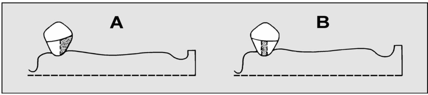
Figure 8.64. Quadrant Example for Loss Pattern #4 of a Distal Extension Defect.

¶ 8.30. Limit and Improve the Tilt
8.30.1. Limit of Tilt. An occlusal plane can be tilted too far laterally or anteroposteriorly with reference to the surveyor spindle as follows:
8.30.1.1. Lateral Limit of Tilt. Given a cast mounted on a surveyor table, a lateral orientation is found where cross arch opposing undercuts are present on abutment teeth. If the tilt is changed so the cross arch opposing undercuts are no longer observable, the cast has been tilted too far laterally.
8.30.1.2. Anteroposterior Limit of Tilt.
8.30.1.2.1. Given a cast mounted on a surveyor table, an anteroposterior orientation is found where mesial and distal zone undercuts are present on the proposed abutments, but the undercuts are not deep enough. If the case is tilted posteriorly until the abutments show adequate distal zone undercuts, minimal mesial zone undercuts must still be observable or the case has been tilted too far posteriorly. The reverse situation is true for anterior tilts in toothborne quadrants.
8.20.1.2.2. Given a cast mounted on a surveyor table, a distofacial undercut on the terminal abutment is found, but the undercut is not deep enough when measured at a neutral tilt. Paralleling the mesiolingual aspect of the terminal abutment with an analyzing rod demonstrates the quadrant’s distal limit of tilt.
8.30.1.2.3. The lim its of anteroposterior tilt for the two quadrants of a case are almost always different. Therefore, the quadrant that tolerates the least amount of tilting before exceeding its limit dictates the anteroposterior orientation for the whole case.
8.30.2. Improving a Tilt. A tentatively acceptable tilt (desirable undercuts present on teeth proposed as abutments) may be modified for the following reasons: to make the RPD look better in the patient’s mouth, to increase the amount of soft tissue contact area under denture bases (saddles) for support and bracing purposes, and to lessen the chances offood im paction between rigid RPD components and oral structures. (Thi s usually means trying to reduce the amount of excess space between the RPD’s rigid parts and the or al structures beneath them.) Three examples of tilt modification are as follows:
8.30.2.1. Example #1, Anterior Extension RPD. In this example, the zone combinations exist as shown in Figure 8.65 with the surveyor table set at 0 degrees lateral and 0 degrees anteroposterior tilt. Undercuts of sufficient depth are present within the zones. Due to pronounced ridge resorption, denture teeth embedded in a resin denture base are the replacement of choice. Observe the tissue height of contour in the anterior area and the depth of the undesirable undercut beneath it. Rem ember, the framework’s path of insertion controls the route the denture base travels to place. A resin de nture base processed on the cast to fit into the sulcus would be prevented from seating in the patient’s mouth by the tissue height of contour. There are two unattractive options open to the dentist under these circum stances. The dentist may:
8.30.2.1.1. Cut the flange back to the tissue height of contour. With this option, the junction line between the plasticand the skin of the mouth would probably become exposed to view, and the anteroposterior bracing effectiveness is definitely reduced.
8.30.2.1.2. Maintain the length of the flange by grinding enough plastic from the tissue surface of the flange to let the denture base (saddle) slip by the height of contour. This option has the serious disadvantage of creating an unacceptable space between the ridge and the tissue surface of the denture base when the RPD is seated. Figure 8.66 shows the same cast tilted posteriorly to minimize the undesirable soft tissue undercut. At this tilt, the flange of the saddle extends into the sulcus without any modification. The border would be concealed and food traps not created. The results of modifying the original tilt seem to be justified. Whether an acceptable framework design can be composed to conform to this path remains to be decided. Notice how all the zones of undercut have changed in size and shape. The mesiofacial zones are considerably smaller. Determine whether undercuts of adequate depth are still present in the original zones. If reevaluation of the case shows the mesiofacial zones are not deep enough, try to find another suitable combination of undercuts with the required depth. The example in Figure 8.67 shows an acceptable alternative. In this figure, midfacial undercuts have been substituted on the anterior abutments.
8.30.2.2. Example #2, Relationship of a Lingual Bar to the Lingual Aspect of the Mandibular Ridge.
8.30.2.2.1. The relationship shown in Figure 8.68 be tween the lingual bar and the ridge is unacceptable. The lingual bar should closely fo llow the contour of the mandibular lingual surface just barely short of contact with the mucosa.
8.30.2.2.2. The lingual bar-to-ridge relationship in Figure 8.69 is satisfactory.
8.30.2.3. Example #3, Equalizing the Proximal Areas Between an Artificial Replacement and the Natural Tooth Next to it.
Figure 8.65. Undesirable Soft Tissue Undercut.

Figure 8.66. Soft Tissue Undercut Minimized.

Figure 8.67. Undercut Substitution.

Figure 8.68. Incorrect Bar Position.

Figure 8.69. Correct Lingual Bar Position.

Figure 8.70. Size of a Proximal Undercut Can Affect Esthetics and Hygiene.

8.30.2.3.1. In Figure 8.70, the artificial replacement for the anterior edentulous area cannot extend distal to the two dotted lines or the RPD will not go to place. The space at the mesial of the lateral incisor is too large and represents a potential food trap. The size of the space in the patient’s mouth might be obvious to the casual observer. The more exaggerated versions of this problem can seriously lim it the ability to produce artificial teeth that are properly shaped.
8.30.2.3.2. In Figure 8.71, the proximal spaces distal to the dotted lines are roughly equal. If desirable undercuts are available for use, this tilt is more acceptable than the one in Figure 8.70. A tilt having adequate undercuts in the right places can be an elusive thing because it does not take much of a change to ruin its distinctive features. When undesirable undercuts are extremely deep, slight tilt modifications of the kind described do not help much. Ask the dentist to resolve the problem in some other way.
Figure 8.71. Increased Potential for an Esthetic, Hygienic Adaptation of an Artificial Tooth.

¶ 8.31. Place Tripod Marks on the Cast
Tripoding is a method of marking a surveyed cast with three dots so the cast or its duplicate can be repositioned on any survey table at exactly the same tilt. This capability is essential when transferring a design from a diagnostic to a master cast and for subsequent blockout procedures.
8.31.1. Place Tripod Marks as Part of the Initial Survey (Figure 8.72)
After finding an acceptable tilt, lock the surveying table in that position. Insert a carbon marker into the surveyor spindle. Bring the tip of the carbon into contact with a feature on the cast, lock the vertical spindle, and mark the surface with a short horizontal line by moving the surveying table on the surveyor base. After the first mark is made, make a mark on two other cast features at the identical spindle height used to place the first dot by sliding the surveying table to bring the carbon marker in contact with two additional areas on the cast. Ma ke a short vertical line through the horizontal carbon mark, using ared pencil to form a cross. Circle the cross with a blue pencil. When placing the marks:
8.31.1.1. Make sure they are widely separated. If imaginary lines connected the marks, they would make the shape of a triangl e. The larger the triangle, the more accurately the cast can be re-tripoded.
8.31.1.2. Place dots on those surfaces of the cast that represent im mobile features of the patient’s mouth. Do not place marks in sulci or on frenums.
8.31.1.3. Place dots on spots that are certain to appear in every impression made. Do not place dots on the land areas of the cast.
8.31.1.4. Try to avoid areas of the cast where the dots might obscure framework design drawings and vice versa.
Figure 8.72. Tripod Marks.

8.31.1.5. Try to choose features that are oriented more vertical ly than horizontally. Tripod marks cannot be placed in undercut areas.
8.31.2. Use Tripod Marks To Find the Tilt They Represent.
8.31.2.1. Take a long, critical look at the cast with the tripod marks. Using cast landmarks, calipers, and a millimeter ruler as guides, place tripod marks in the identical spots on the master cast.
8.31.2.2. Place the duplicate cast on a surveying table. Lock down the surveying table at a position where the cast is neutrally tilted.
8.31.2.3. Bring the tip of an analyz ing rod into contact with one of the marks and lock the vertical spindle.
8.31.2.4. Without changing the tilt of the table, check to see if the tip of the analyzing rod can contact the other two marks. (It probably cannot.)
8.31.2.5. Choose one of the two remaining two marks and tilt the cast until the analyzing rod can contact both marks. It may be necessary to raise or lower the spindle. Be sure to relock the spindle. Once two marks are level, tilt the cast around an imaginary axis through these tw o marks until the third mark comes into alignment, again making adjustments in the height of the spindle as necessary.
8.31.2.6. Continue to make slight adjustments to the tilt of the table and the vertical setting of the spindle refining the positions of the marks until the rod can contact all three marks without changing the height of the spindle or the tilt of the table. NOTE: The objective is to f ind the single tilt where all three dots can be brought into contact with the tip of an analyzing rod that is locked down at one constant vertical height.
¶ 8.32. Mark the Tooth and Soft Tissue Survey Lines With a Carbon Marker
8.32.1. After choosing a path of insertion and tripoding the cast, the next step is to make a “contour map” of the height of contour of tooth and tissue structures (Figure 8.73). Place a carbon marker in the vertical spindle of the surveyor . Move the cast and carbon marker, one against the other, by sliding the table around on the base of the surveyor.
Figure 8.73. Mark Heights of Contour With a Carbon Marker.

8.32.2. To properly survey a cast, first trace survey lines at the heights of contour of the teeth by placing the side of the carbon marker against the height of contour of the tooth and the tip of the marker against the bottom of the undercut. Outline the entire undercut area.
8.32.3. Next, simultaneously mark the soft tissue he ights of contour with the side of a carbon marker and the lower limit of the undercut with the tip of the marker.
8.32.4. Survey lines have value for determining the proper location of clasp arms, minor connectors, and major connectors in the overall design; choosing suitable substitutes for missing teeth and soft tissue; and blocking out undesirable undercuts before duplicating the master cast in refractory material. Survey lines also are a guide to the dentist to show w here tooth contours must be altered to eliminate or reduce undesirable undercuts or to establish guide plane prior to the final impression.
¶ 8.33. Decide Where Tooth Modifications Will Enhance RPD Function
Four components of the RPD usually require modification of tooth surfaces by the dentist prior to making the final impression. These components should be marked in red on the diagnostic cast.
8.33.1. Rests. Rest seats almost always require preparation. Embrasure clasp assemblies with their associated rests often requiresignificant tooth reduction.
8.33.2. Guide Planes. Guide planes should be as long and flat as possibl e. When the guide plane is next to an extension base, it is also kept flat in a buccolingual plane.
8.33.3. Clasps. Normally, the height of contour of the tooth is high at the line angle of the tooth where the shoulder of the clasp contacts the tooth. In order for a suprabulge clasp to drop down toward the gingival of the tooth without crossing the undercut, the dentist must reshape the tooth to lower the survey line. Abnormally high survey lines are most pronounced on mandibularmolars that are the distal abutment in a tooth-borne RPD. These areas must be adjusted for proper clasp placement, especially on the mesiolingual.
8.33.4. Plating. Sometimes tooth undercuts will interfere with plating. This is particu larly prevalent with crowded or rotated lower anterior teeth. These undercuts should be removed by the dentist, if possible.
¶ 8.34. Mark the Location of Retentive Tips
Now that the cast has been tripoded and surveyed and a design decided upon, locate the depth of desired undercut using a suitable undercut gauge. Mark the proper depth of undercut with a discreet red dot. This dot is the definitive location of the lower edge of the retentive clasp tip.
¶ 8.35. Select a Clasp Assembly for Each Abutment Tooth
Paragraphs 8.29.4 and 8.29.5 deal with finding an acceptable tilt and make suggestions for zones of undercut in specific combinations for the different case classifications. The problem is to select clasp shapes that are best able to get to thos e zones. The ability of a clasp to eng age an undercut located in a particu lar spot on a tooth’s su rface is limited by occlusion, esthetic considerations, presence of soft tissue undercuts, classification of the case, location of the undercu t, incidence of decay associated with the clasp form, and perio dontal integrity of abutment teeth as follows:
8.35.1. Factors Influencing Choice of a Clasp Assembly.
8.35.1.1. Occlusion.
8.35.1.1.1. Circumferential Clasp Assemblies.
8.35.1.1.1.1. When upper and lower teeth are in centric occlusion, a simple circumferential clasp requires a passage space 1.25 mm wide and 1 mm high through an embrasure area. Embrasure clasps need a channel 2 mm wide and 1 mm high. If the space does not exist naturally, it is up to the dentist to adequately open up embrasure channels to accommodate clasp parts (body and arms). An 18-gauge round wire is about 1 mm in diameter. Dentists sometimes use one or two of these wires to test if enough room exist (Figure 8.74)
Figure 8.74. Embrasure Clasp Clearance.

8.35.1.1.1.2. Another important consideration is that a high survey line on an abutment tooth can approach the shearing cusp of an opposing tooth so closely that there is no room for a clasp arm. When centric occlusion is very “tight” (opposing teeth contact solidly and cusps overlap steeply), start thinking about infrabulge alternatives to circumferential clasping.
8.35.1.1.2. Bar Clasp Assemblies. A bar clasp cannot be used in posterior segments where noteeth are missing. The design features of a bar clasp require that the approach arm originate from a denture base area. In areas where edentulous spaces exist, a bar clasp interferes with occlusion less than circumferential clasps because a bar clasp d oes not penetrate through embrasures completely.
8.35.1.2. Esthetic Considerations.
8.35.1.2.1. Circumferential Clasp. A circumferential clasp is less visible on teeth with low survey lines. If the retentive arm is made to approach a mesiofacial undercut from the distal aspect of an abutment tooth and the clasp arm travels as close to the gingival margin as the survey line permits, the metal does not show as much.
8.35.1.2.2. Bar Clasp. A bar clasp’s approach arm crosses gingival surfaces on the way to a zone of undercut. To the extent that most people do not expose gum tissue when they talk or smile, I-bar clasps can be less conspicuous than many circumferential types.
8.35.1.3. Presence of Soft Tissue Undercuts. This consid eration affects the use of bar clasps as follows:
8.35.1.3.1. The approach arm of a bar claspshould contact tissue between its point oforigin and place where the arm crosses the gingiv al margin. The presence of an undesirable soft tissue undercut in the path of a bar clasp’s approach arm is one of the most serious contraindications to its use. Figure 8.75 shows a high, deep, soft tissue undercut.
Figure 8.75. Soft Tissue Undercut.

8.35.1.3.2. Given the condition illustrated in Figure 8.75, the only option for positioning a bar clasp’s approach arm is shown in Figure 8.76. This option is unacceptable. Given the conditions shown in Figure 8.77, a proper relationship can be developed between an approach arm and underlying tissue (Figure 8.78).
8.35.1.3.3. There are instances where a tooth leans out so far into the vestibule the facial surface blocks satisfactory placement of an a pproach arm. The problem most frequently occurs in the caninearea (Figure 8.79)
8.35.1.4. Classification of the Case.
8.35.1.4.1. Extension cases requirespecial attention. Clasp assemblies that use a mesial rest in conjunction with a distal undercut for distal extension case abutments produce fewer tilting forces on the teeth.
Figure 8.76. Incorrect Approach Arm Relationship.

Figure 8.77. No Soft Tissue Undercut.

Figure 8.78. Acceptable Approach Arm Relationship.
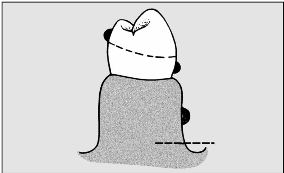
Figure 8.79. Bar Clasp Use Is Blocked.

8.35.1.4.2. The same is true when using a distal rest together with a mesial zone of undercut for anterior extension situations. Extension RPDs must be thought of in a different way than toothborne RPDs because part of the support of the RPD comes from compressible tissues. As a result, the RPD moves much more when the patien t chews. The clasp assemblies must be chosen to consider this movement. There are three primary concepts for dealing with this movement; stress-breaking, stress-releasing, and stress-distribution.
8.35.1.5. Location of the Undercut. Most forms of circumferential and bar clasps are best suited to engaging undercuts in mesial or distal zones. The I-bar is an exception. It is specifically designed to engage midfacial or midlingual undercuts.
8.35.1.6. Incidence of Decay Associated With a Clasp Form. There are dental patients who are unusually prone to developing cavities. Because bar clasps generally contact less tooth surface than circumferential clasps, the chances for decay should be somewhat reduced.
8.35.1.7. Periodontal Integrity of Abutment Teeth.
8.35.1.7.1. Circumferential Clasps. Circumferential clasps are stiffer than bar varieties and have more potential to do damage while the RPD is being inserted or removed. Clasp arms placed close to the occlu sal surface of a tooth be cause of high survey lines act to widen the chewing table. This in creases the load an a butment must bear. The additional burden could be too much for the tooth’s supporting structures to tolerate.
8.35.1.7.2. Combination Clasps. There is an authoritative body of opinion that believes combination clasps are less abusive to teeth than cast clasps because the wire retentive arm of a combination clasp has a round cross-section and can flex in many planes instead of just one.
8.35.2. Common Clasp Assembly Applications. Observe how the common clasp forms relate to survey lines and zones of undercut in the following examples. Although it is impossible to show every conceivable situation, these limited number of examples are supposed torepresent principles that can be applied to a much larger range of possibilities:
8.35.2.1. Circumferential Clasp Assemblies.
8.35.2.1.1. Simple Circumferential.
8.35.2.1.1.1. Two arms project from the clasp’s body and terminate on the sides of the tooth opposite from the clasp assembly’s rest. A simple circumferential clasp is versatile, easily adjusted, and can be relatively inconspicuous. Limiting factors permitting, this is the circumferential clasp of choice.
8.35.2.1.1.2. The undercuts used are the mesial or distal zones on facial or lingual surfaces. Example #1 shows a toothborne quadrant and the clasp arms are convergent (Figure 8.80). Example #2 shows a toothborne quadrant and the clasp arms are divergent (Figure 8.81). Example #3 shows a distal extension quadrant, distal abutment, mesial rest, and distofacial zone (Figure 8.82). Example #4 shows an anterior extension case, anterior abutment, distal rest, and mesiofacial zone (Figure 8.83).
Figure 8.80. Simple Circumferential Clasp Assemblies With Convergent Retentive Arms (Example #1).

Figure 8.81. Simple Circumferential Clasp Assemblies With Divergent Retentive Arms (Example #2).

8.35.2.1.2. Embrasure (Crib)
This clasp assembly consists of two circumferential clasps joined at their bodies, and a single minor connector. The assembly passes between two adjacent natural teeth. One retentive arm engages the mesial zone of undercut on the anterior abutment, and the other retentive arm uses a distal undercut on the posterior abutment (Figure 8.84).
Figure 8.82. Simple Circumferential Clasp Assembly With Distal Extension Situation (Example #3).

Figure 8.83. Simple Circumferential Clasp Assembly With Anterior Extension Situation (Example #4).

Figure 8.84. Embrasure Clasp Assembly.

8.35.2.1.3. Ring Clasp With Strut Assembly.
8.35.2.1.3.1. Instead of two arms, this circumferential clasp has a single arm that almost completely encircles the tooth. The ring clasp assembly uses two rests, and a supplemental strut braces the arm. An unbraced ring clasp is highly susceptible to accidental bending. The strut leaves a major c onnector or a denture b ase area, crosses over soft tissue surfaces, and intersects with the clasp arm halfway between the retentive tip and the minor connector. The strut should remain in light contact with the soft tissue it traverses.
8.35.2.1.3.2. It logically follows that a properly braced ring clasp is contraindicated when there is an undesirable soft tissue undercut in the path of the strut. Mesial zone undercuts on molars can be difficult to get to. Braced ring clasps are a design compromise that can fulfill that purpose. The undercuts most fr equently inv olved are mesiolingual on mandibularmolars and mesiofacial on maxillary molar teeth. Example #1 shows the ring clasp used to enter a mesiolingual zone on a mandibularmolar; Figure 8.85 represents a lingual and buccal v iew. Example #2 shows the ring clasp used to enter a mesiofacial zone on a maxillary molar; Figure 8.86 represents a buccal and a lingual view.
Figure 8.85. Ring Clasp Assembly, Mandibular Arch (Example #1).

Figure 8.86. Ring Clasp Assembly, Maxillary Arch (Example #2).

8.35.2.1.4. Reverse Action (Hairpin)
8.35.2.1.4.1. The distinctive feature of this circumfe rential clasp is that the retentive arm reverses itself on the face of the tooth (Figur e 8.87)
The retentive tip of a hairpin clasp enters a zone of undercut immediately gingival to the retentive arm’s shoulder.
8.35.2.1.4.2. One problemassociated with hairpin clasps is that they cover a great deal of tooth surface. They are highly visible and can not be used on teeth having short clinical crowns.
Figure 8.87. Hairpin Clasp Assemblies.

8.35.2.1.4.3. Perhaps the most serious shortcoming of the hairpin clasp is its susceptibility to breakage. It is very difficult for the dental laboratory technician to shape and polish this retentive arm without destroying its taper. As a result, this clasp usually flexes at the weakest point (the angle of the hairpin) and fractures. However, it may be used to enter distofacial undercuts on canines, distofacial u ndercuts on premolars, and mesiofacial infrabulge zones of molars when soft tissue undercuts prevent the use of bar approach arms.
8.35.2.1.5. Half-and-Half (Split)
This clasp assembly consists of mesial and distal minor connectors, each of which bears a rest and an arm. The split clasp can engage most mesial or distal zone undercuts on the buccal or lingual. Figure 8.88 represents buccal and lingual views of a split clasp used in this manner.
Figure 8.88. Half-and-Half (Split) Clasp Assembly.

8.35.2.1.6. Multiple Circumferential. This clasp assembly c onsists of two opposing circumferential clasps joined at the terminal end of the tworeciprocal arms. A separate minor connector attaches each of the joined clasps to the framework. The reciprocal arms are united to provide increased support for two or three weak or isolated teeth. Buccal and lingual views of the multiple circumferential clasp assembly are presented in Figure 8.89.
Figure 8.89. Multiple Circumferential Clasp Assembly.

8.35.2.1.7. Combination Circumferential.
8.35.2.1.7.1. The combination clasp consists of a wrought wire retentive arm and a cast reciprocal arm. The wrought wire arm may be embedded in the framework during the waxing and casting procedures, the wire may be soldered to the framework after the framework is cast, or the wire may be embedded in the acrylic resin denture base during processing.
8.35.2.1.7.2. Some authorities maintain that a wrought wire arm is detrimentally altered by high temperature. Therefore it is advisable to solder the wrought wire to the framework at a point well away from the flexible retentive end of the wire.
8.35.2.1.7.3. The combination clasp is believed to exert less destructive force on an abutment because ofits high flexib ility. By the same token, a wrought wire arm is easily bent out of shape.
8.35.2.1.7.4. The most common uses of the combination clasp are on an abutment tooth adjacent to a distal extension b ase where the only un dercut available lies in the mesiofacial zone (Figure 8.90) and on periodontally weak abutments. The combination clasp may also be used to engage a midfacial undercut with the mid-body portion of the clasp. In this case, both the shoulder and tip of the clasp would be above the survey line. The depth of undercut required is usually .010 or .015 and rarely .020 inch. The wrought wire used may be either 18-gauge round platinum-gold-palladium (PGP) wire or Ticonium wire.
8.35.2.1.8. Twin Flex. A special variety of wro ught wire clasps is the twin flex. It is used in interproximal retentive undercuts, usually in the anterior where there is a desire to avoid display of metal. The clasp extends underneath the major connector, wh ere it is soldered, into the proximal undercut (Figure 8.91). It requires significant vertical space and is difficult to construct.
Figure 8.90. Buccal View of Combination Circumferential Clasp Assembly.

Figure 8.91. Lingual View of Twin Flex Clasp Beneath Lingual Major Connector.

8.35.2.2. Bar Clasp Assemblies.
8.35.2.2.1. T-Bar Clasp. This clasp ordinarily uses undercuts located in facial or lingual zones adjacent to an edentulous space. If such a clasp had a long approach arm and was cast in chrome, it should engage .015 inch undercut. When the retentive tip of a T-bar clasp engages a distofacial undercut, the bracing tip falls on the tooth’s highly visible mesial surface. However, this component provides a valuable bracing function. The T-bar clasp is not indicated on canines and first premolars. Two examples of T-bar clasp assembly use are in Figures 8.92 and 8.93.
8.35.2.2.2. Modified T-Bar. When esthetics is most important, the bracing tip of a T-bar clasp can be omitted. When the bracing tip of a T-bar clasp is omitted, the result is called a modified T or 1/2 T. Because the modified T is somewhat more esthetic than a T-bar clasp, the modified T may be used on anteriorly positioned abutments. Two examples of modified T bar clasp assemblies are shown in Figures 8.94 and 8.95.
Figure 8.92. T-Bar Clasp Assemblies—Toothborne Quadrant.

Figure 8.93. T-Bar Clasp Assembly—Distal Extension Situation.

Figure 8.94. Modified T-Bar Clasp Assemblies—Toothborne Quadrant.

Figure 8.95. Modified T-Bar Clasp Assembly—Distal Extension Situation.

8.35.2.2.3. I-Bar. In contrast to other forms of the bar clasp, there are no bracing or retentive tips diverging from the approach arm of an I-bar clasp. Instead, the end of the approach arm acts as a retentive tip. The original I-bar configuration was devised to reduce bar clasp visibility, and it is still used for that purpose. I-bar clasps cast in chrome-alloy usually use .010 inch mesiofacial or mesiolingual undercut. An example of a I-bar clasp assembly is shown in Figure 8.96.
Figure 8.96. I-Bar Clasp Assembly—Toothborne Quadrant.

8.35.2.3. Stress-Releasing Clasp Assembly Applications. The stress-releasing concept is very popular with some dentists. It uses various specialized clasp assemblies in an attempt to minimize torquing forces on the terminal abutments of distal extension RPDs. These include the I-bar, RPI, modified T-bar, and RPA concepts. While each of these techniques has its own peculiarities, they all have in common a mesial rest on the terminal abutment and distal guide plane, and they use a midbuccal, mesial-midbuccal, or distobuccal retentive undercut. The major connector on the lingual is kept at least 5 mm below the gingival margin.
8.35.2.3.1. I-Bar Clasp. This technique, originally described by Dr. Kratochvil, uses a long flat guide plane on the distal of the abutment that contacts the tooth from 1 to 2 mm on the tissue up to the occlusal surface. There is no relief under this metal except for blockout in undercut areas. The guide plane may wrap slightly around the distolingual line angle. A distal rest accompanies the mesial rest on the next anterior tooth. The I-bar clasp engages a midbuccal undercut.
8.35.2.3.2. RPI Clasp. Developed by Dr. Krol, RPI stands for rest, proximal plate, and I-Bar (Figure 8.97).
Figure 8.97. RPI Clasp Assembly.

8.35.2.3.2.1. Rest. The abutment tooth contains a mesio-occlusal rest. A minor connector is attached to this rest in the mesiolingual embrasure. The minor connector is constructed to avoid touching the distolingual surface of the adjacent tooth.
8.35.2.3.2.2. Proximal Plate. The superior edge of the proximal plate engages about 1 mm of the bottom of the distal guide plane. The lingual margin of the plate follows the curvature of the abutment far enough so the remaining distance to the minor connector is less than the width of the tooth. The proximal plate is 1 mm thick and joins the framework at right angles. At this junction, the portion of the proximal plate adjacent to the gingival tissue is 3 mm wide anteroposteriorly. The tissue under this step is relieved with one thickness of 30-gauge wax.
8.35.2.3.2.3. I-Bar. The retentive tip of an I-bar has a 2 mm span of contact with tooth surface, and the bottom of this contact is located at .010 inch undercut. The approach arm of the I-bar should be located at least 3 mm away from the gingival margin.
8.35.2.3.2.4. Guide Planes. Before a final impression is made, the dentist prepares a guide plane at the occlusal 1/3 of the abutment’s distal surface. The distal guide plane is about 2 to 3 mm in height. An undercut must be present below the guide plane. This lets the proximal plate disengage from the tooth when the distal extension part of the RPD is loaded. The dentist has the option of preparing another 2 to 3 mm guide plane at the occlusal 1/3 of the abutment’s mesiolingual surface. This acts to increase the reciprocating and bracing effectiveness of the minor connector.
8.35.2.3.3. RPA. When an infrabulge clasp cannot be used, but the dentist wants to use a stress releasing design, an RPA concept may be used. This concept uses a mesial rest, a proximal plate, and a circumferential (Akers) clasp into a distobuccal undercut. The important point to remember in this technique is the superior edge of the circumferential clasp must contact the abutment tooth only at the survey line until the retentive tip engages the tooth in the retentive undercut. The rest of the clasp does not contact the tooth at all. The rest and proximal plate is the same as the RPI concept.
8.35.2.3.4. Modified T-Bar. When a stress-relieving concept is used, but only distobuccal undercut is available, a modified T-bar may be used. The clasp assembly is made the same as an RPI, except a modified T-bar instead of an I-bar is used.
¶ 8.36. Decide If All Requirements for Rests Have Been Met
Some general guidelines for placing rests are:
8.36.1. Rests are almost always placed on teeth adjacent to edentulous spaces because that is where support requirements are greatest. Common exceptions include when a specialized clasping system is used such as a stress-releasing concept and when opposing cusps make it very difficult for the dentist to create room for a rest.
8.36.2. A clasp assembly almost always has a rest associated with it.
8.36.3. Rests are used to provide indirect retention in extension cases.
8.36.4. There is a commonly occurring, special situation where auxiliary rests are an excellent idea. In mandibular posterior toothborne RPDs that use a lingual bar major connector, the anterior part of the bar should be supported with auxiliary rests in the mesial fossa of the first premolar teeth.
¶ 8.37. Draw the Design in Appropriate Coded Colors
(NOTE: This is the last step in the survey and design procedure.) The choices among RPD components have been made as the survey procedure has progressed. All that remains is to draw an accurate representation of the RPD on the cast. Per Figure 8.98, the primary guides for the drawing are the survey lines, points of undercut marked in red pencil, vertical overlap line drawn on the lingual surfaces of the upper anterior teeth, and anatomical features of the cast as follows:
Figure 8.98. Surveyed and Designed Casts.

8.37.1. RPD Design Color Code. Standard colors are reserved for drawing particular parts of an RPD design on a cast. These colors help to delineate components clearly and improve the quality of communication between the dentist and the technician as follows:
8.37.1.1. Red.
8.37.1.1.1. Diagnostic Casts. The color red is used to indicate areas in the patient’s mouth that require preparation or recontouring such as rest seats, interfering cusps in the opposing arch, and guide planes. Red is used to mark the point where the retentive tip of a clasp will be positioned. Tissue relief is also marked in red.
8.37.1.1.2. Master Casts. The use of the color red on a master cast is limited to marking points of undercut for positioning clasp retentive tips, and tissue relief areas.
8.37.1.2. Blue. The color blue is used to outline the extent of acrylic resin denture base coverage.
8.37.1.3. Brown. The color brown is reserved for outlining metal parts of the RPD.
8.37.1.4. Black. Tooth and soft tissue survey lines are represented on the cast in the color black. Special instructions may also be written in black.
8.37.2. Sequence and Method of Drawing the Design. The suggested order for the steps in drawing the design on a diagnostic cast are:
8.37.2.1. Rests. The rest seats are colored.
8.37.2.2. Clasps. No matter what kind of clasp is drawn, the full assembly must take in more than 180 degrees of the tooth’s circumference.
8.37.2.2.1. Circumferential Clasp.
8.37.2.2.1.1. Retentive Arm. The shoulder (proximal one-third) of a retentive arm is located above the survey line. The retentive tip (terminal one-third) ends on the undercut previously marked in red.
8.37.2.2.1.2. Reciprocal Arm. The gingival edge of the reciprocal arm conforms to the survey line. If the survey line approaches the occlusal surface of a posterior abutment or the clinical crown is very short, consider using reciprocal plating. The occlusal edge of reciprocal plating terminates about 0.5 mm occlusal to the survey line.
8.37.2.2.2. T-Bar and Modified T-Bar Clasps.
8.37.2.2.2.1. Approach Arm. As the approach arm leaves the denture base, the gingival edge of the arm is located at least 3 mm from the abutment’s gingival crest. The edge of the arm nearest the sulcus must not dip below any soft tissue survey lines that might be present. The arm must not interfere with normal sulcus mobility. When the approach arm curves to make contact with the tooth surface, it is drawn so it intersects the gingival crest line at 90 degrees. The approach arms of T-bar and modified T-bar clasps make first contact with the tooth at the survey line.
8.37.2.2.2.2. Bracing Tip. (T-bar clasps only) The gingival edge of an approach arm ’s bracing tip falls on, or very close to, the survey line.
8.37.2.2.2.3. Retentive Tip. The retentive tip extends from the approach arm ’s contact with the survey line to the point of undercut on the tooth’s surface previously marked in red.
8.37.2.2.2.4. Reciprocal Arm. The considerations are the same as those for circumferential clasp reciprocal arms (paragraph 8.37.2.2.1.2).
8.37.2.2.3. I-Bar Clasps That Use Reciprocal Arms.
8.37.2.2.3.1. Approach Arm. The considerations for an I-bar approach arm ’s soft tissue relationship are the same as the T-bar and modified T-bar clasps (paragraph 8.37.2.2.2.1).
8.37.2.2.3.2. Retentive Tip. The I-bar’s retentive tip is the end of its approach arm. The tip makes first contact with the tooth at the .010 inch undercut mark and extends occlusally or incisally for 2 mm.
8.37.2.2.3.3. Reciprocal Arm. The considerations are the same as for the circumferential clasp reciprocal arms (paragraph 8.37.2.2.1.2).
8.37.2.2.4. RPI Bar Clasp Assemblies (Figure 8.97)
8.37.2.2.4.1. Approach Arm and Retentive Tip. The considerations are the same as for I-bar clasps that use conventional reciprocal arms (paragraph 8.37.2.2.3).
8.37.2.2.4.2. Minor Connector. The minor connector is drawn so it does not touch an adjacent tooth.
8.37.2.2.4.3. Distal Plate. The plate is supposed to contact the cervical 1 mm of the preprepared distal surface guiding plane. In clasps that engage midfacial undercuts, the assembly plating starts at the abutment’s distofacial corner. It extends around the distolingual corner enough so the resultant space between the plate and the minor connector is less than the width of the tooth (encirclement).
8.37.2.3. Major Connectors.
8.37.2.3.1. Defining the Borders of Major and Minor Connectors.
8.37.2.3.1.1. Avoid adding to the prominence of natural convexities by covering their crests with metal.
8.37.2.3.1.2. Cover gingival margin tissue completely by an adequately relieved part of the RPD, or position the component at least 4 to 6 mm from the gingiva.
8.37.2.3.1.3. Cross gingival crest tissue at right angles to the gingival margin.
8.37.2.3.2. Maxillary Major Connectors.
8.37.2.3.2.1. Anterior Borders of Straps. Anterior borders of straps should follow the valleys between rugae as much as possible. When crossing over rugae, do it at 90 degrees to their crests. Stay 6 mm from gingival margins where possible. When utilizing lingual plating, be aware of where the line of impact between upper and lower incisors is drawn; do not extend lingual plating incisal to that line. The leading edge of a lingual plate is scalloped. The plate covers the lingual gingival one-third of the tooth in the cingulum area and rises to cover interproximal spaces up to the contact points. An exception is made when large diastemas are present. Cingulums are covered, but interproximal spaces are not. Make sure a rest supports each end of the plate.
8.37.2.3.2.2. Lateral Borders of a Maxillary Major Connector. Either plate the lingual surface of a tooth or stay 6 mm from the gingival border.
8.37.2.3.2.3. Posterior Border of a Maxillary Major Connector. A strap should traverse the palatal vault anterior to the vibrating line. Full palatal coverage ends on the vibrating line in a manner similar to complete dentures.
8.37.2.3.2.4. Width of Straps. Maxillary strap major connectors should be made as wide as the combined width of the maxillary second premolar and first molar.
8.37.2.3.2.5. Placement of Straps and Horseshoes Relative to the Palatal Vault (Figure 8.99)
The hard palate makes an ascent from the incisive papilla to the height of the vault. Then it proceeds more or less straight back to the vibrating line. Try to draw a strap or a horseshoe so at least part of the major connector straddles the place where the palatal angle changes. A strap gets additional strength from the “angle iron” effect.
Figure 8.99. Placement of Strap and Horseshoe Major Connectors Relative to Palatal Vault Shape.

8.37.2.3.3. Mandibular Major Connectors.
8.37.2.3.3.1. Lingual Bar. The superior edge of a mandibular lingual bar should clear the crests of the gingiva by 4 mm. The inferior edge should be placed high enough that it does not interfere with the normal mobility of the floor of the mouth. In distal extension cases, lingual bars end cleanly on a vertical line with the distal surface of the terminal abutment.
8.37.2.3.3.2. Lingual Plates. Mandibular lingual plates are outlined in the same manner as their maxillary counterparts (paragraph 8.37.2.3.2.1).
8.37.2.4. Minor Connectors.
8.37.2.4.1. Minor Connectors That Join Clasp Assemblies and Auxiliary Rests to Major Connectors. These types of minor connectors should be sturdy enough for rigidity, but sufficiently streamlined so patients can tolerate their presence. Minor connectors leading to clasp assemblies and auxiliary rests must cross a gingival margin at 90 degrees to the gingival line.
8.37.2.4.2. Denture Resin Open Retention Grids. Retention grids should always extend over the crest of the ridge to prevent midline fractures of the denture base. Grids are constructed to avoid the retromolar pads in the mandibular arch. Adequate bulk and strength in the metal at the junction of the grid and the major connector is essential as follows:
8.37.2.4.2.1. Mesh. Because mesh holes can be obliterated during the casting process, use prefabricated mesh patterns with maximum size openings.
8.37.2.4.2.2. Ladder-Type Grid Retention. This ladder-like configuration is formed from round and half-round wax shapes that extend over a ridge’s crest onto its facial surface. The ends of the bars are connected for strength. It is also common to place reinforcing elements lingual to the crest of the ridge. Longitudinal reinforcing struts are never placed on top of a residual ridge. Struts located in this manner reduce the amount of room available for setting denture teeth and act as a wedge on the resin to cause breakage. The struts should be about 6 mm apart.
8.37.2.5. Resin and Metal Denture Base Borders.
8.37.2.5.1. Anterior and Lateral Extent. Anteriorly and laterally, denture base borders are determined by soft tissue survey lines. Survey lines permitting, denture base borders should extend into the sulci.
8.37.2.5.2. Posterior Extent. The following rules for the posterior extension of an RPD are not subject to compromise: (1) The maxillary arch full palatal coverage ends on or anterior to the vibrating line, (2) a maxillary arch distal extension denture base must extend into the hamular notch, and (3) a mandibular arch distal extension denture base must cover at least half of the retromolar pad.
8.37.2.6. Finish Lines. Finish lines show where there will be a 90-degree butt joint between acrylic resin and metal. When the tissue surface of the denture base will be made of resin, there will be an internal and external finish line. With metal bases, there will only be an external finish line. Internal and external finish lines cannot line up over each other because the retentive grid could be seriously weakened. Normally, the external finish line is placed toward the center of the arch from the internal finish line.
8.37.2.6.1. Internal finish lines should be placed about 1 to 2 mm from the survey line adjacent to the proximal areas of the edentulous areas. This creates an area of metal next to the gingival margin. Only mesh and ladder-type retention have internal finish lines.
8.37.2.6.2. External finish lines should be drawn, keeping in mind where the denture teeth will be placed. The metal and resin should provide a smooth transition from the major connector to the denture teeth and should create a natural contour.
8.37.2.6.3. Internal and external finish lines merge as they approach the facial or distal of the denture base.
8.37.2.7. Supplemental Directions. There are words and symbols used to explain the drawing on a cast more fully. These words and symbols are written in pencil or indelible ink boldly and neatly on the soft tissue portion of the cast adjacent to the appropriate area. Following is a list of words, symbols, and abbreviations for use on casts:
8.37.2.7.1. Beads. (Always spelled out.)
8.37.2.7.2. BP. Braided post.
8.37.2.7.3. F. Facing.
8.37.2.7.4. GP. Guide plane.
8.37.2.7.5. MP. All-metal pontic.
8.37.2.7.6. Mesh. (Always spelled out.)
8.37.2.7.7. MV. Metal pontic with an acrylic resin veneer.
8.37.2.7.8. Onlay. (Always spelled out.)
8.37.2.7.9. PGP. Platinum gold palladium wire.
8.37.2.7.10. RAP. Reinforced acrylic pontic.
8.37.2.7.11. Tube Tooth.
8.37.2.7.12. WW. Wrought wire.
8.37.2.7.13. Red-Rimmed Circle. Areas to be relieved or recontoured.
¶ 8.38. Protect the Design Against Smudging
To prepare the formula for a paint-on cast sealant, prepare a concentrated solution consisting of 50 gm of cellulose acetate, 12.5 cc of diethylphthalate, and 1 pint of acetone. Mix the ingredients and let the solution set for 24 hours. Then dilute l part of the concentrate to 10 parts of the acetone. Paint this onto a designed cast to protect the lines against smudging. NOTE: If these ingredients are not available, mix 1 part of shellac with 10 parts of methyl alcohol to make another satisfactory sealant.
¶ Section 8D — Master Casts, Record Bases and Occlusion Rims, Cast-Mounting Procedures, and Design Transfer to the Master Cast
¶ 8.39. Final Impressions and Master Casts
8.39.1. Pouring a final impression to make a master cast is one of the most crucial steps in RPD fabrication. The cast has to be as accurate, dense, and strong as possible. To obtain these qualities, pour an alginate impression within 10 minutes of removing it from the patient’s mouth. This also means pouring a rubber base impression within the first hour.
8.39.2. For maximum density and strength, use a vacuum spatulated mix of artificial stone to pour final impressions. Use the two-step method mentioned in Chapter 7, paragraph 7.25, to pour impressions for RPD construction, or box them with a 50:50 mix of plaster and pumice before pouring them according to Chapter 7, paragraphs 7.34 and 7.35. Trim the cast according to directions in Chapter 7, paragraph 7.23.
¶ 8.40. Mounting the Master Cast in an Articulator
8.40.1. Introduction. At this time, the need for this procedure is a value judgment. Some situations require it, while others do not. Often, it is not possible to make intelligent survey and design estimates without mounting the casts first. This can be true even if a fully surveyed and designed diagnostic cast is available as a guide. Some reasons for this would be:
8.40.1.1. Attachments for facings, reinforced acrylic pontics, and tube teeth must be cast as part of the framework.
8.40.1.2. A doubt exists about how opposing teeth fit against one another in maximum intercuspation, and this element of doubt affects the design of the RPD.
8.40.1.3. One or more natural teeth are in infrao cclusion relative to the opposing teeth. The dentist is incorporating a metal onlay into the framework design to compensate for the problem.
8.40.1.4. The dentist is using the RPD toree stablish a proper occlusal vertical dimension. Master casts are usually mounted after the framework is cast in order to:
8.40.1.4.1. Find and grind away places on the casting that interfere with the patient’s natural occlusion,.
8.40.1.4.2. Position artificial replacements for missing natural teeth,.
8.40.1.4.3. Correct the denture base processing error.
8.40.2. Maximum Intercuspation (MI) Mounting When No Occlusion Rims Are Being Used (Figure 8.100)
The assumptions are that enou gh natural teeth remainto fit the casts into the patient’s MI and the articulator is a fixed guide in strument (or a semiadjustable instrument used as a fixed guided instrument). The mounting procedures are as follows:
8.40.2.1. Establish proper settings of the Hanau H2 se miadjustable articulator ifit is being used as a fixed guided instrument.
8.40.2.1.1. Make the top of the incisal guide pin flush with the top of the maxillary member. Set the incisal guide table at 0 degrees.
8.40.2.1.2. Set the horizontal condylar indications at 30 degrees and the lateral condylar guidance at 15 degrees.
8.40.2.1.3. Lock the condyle elements against the centric stops.
Figure 8.100. MI Mounting.

8.40.2.2. Make sure all plaster nodules and debris have been removed from the occlusal surfaces of the teeth on the cast. Index the base of the cast.
8.40.2.3. Place the casts in maximum intercuspation and stabilize them against shifting with sections of coat hanger wire and stick compound.
8.40.2.4. Mount the maxillary cast in an average manner (Chapter 6, paragraph 6.12)
8.40.2.5. Invert the articulator onto an appropriate stand.
8.40.2.6. Attach the lower cast to the lower member.
8.40.3. Record Bases and Occlusion Rims Needed To Perform the Mounting. These are used when not enough opposing natural teethexist to find the patient’s MI:
8.40.3.1. Record Base and Occlusion Rim Construction (Figure 8.101)
8.40.3.1.1. Record Bases.
8.40.3.1.1.1. Self-curing acrylic resin may be used to fabricate record bases on partially edentulous casts just as they are made for complete denture cases, except for the obvious modifications dictated by the presence of teeth on the casts (Chapt er 7, paragraphs 7.40 and 7.41)
8.40.3.1.1.2. The three biggest problems associated with record base construction for partially edentulous casts are accidentally lock ing the record base material into the tooth and tissue undercuts while the record base is being made, distorting and breaking the record base, and carelessly scuffing the master cast.
8.40.3.1.1.3. Before starting record base cons truction, check for deep, bilaterally opposing undercuts and either avoid them or block them out. Always reinforce the anterior lingual area of a mandibular record base with a coat hanger w ire. Remember, once the shape of a master cast is changed with a damaging influence (abrasion, erosion, or shipping), the cast cannot be used for RPD fabrication.
Figure 8.101. Record Base and Occlusion Rim Construction.

8.40.3.1.2. Occlusion Rims. Mak e occlusion rims a little wider and higher than adjacen t natural teeth.
8.40.3.2. Maxillary Cast Mounting. Mount the maxillary cast according to the dentist’s wishes by either the av erage method (Chapter 7, parag raph 7.47.1) or the facebo w transfer method (Chapter 7, paragraph 7.47.2).
8.40.3.3. Mandibular Cast Mounting. Mount the mandibular cast using procedures described in Chapter 7, paragraph 7.48.
¶ 8.41. Transferring the Survey and Design to the Master Cast
8.41.1. After he or she receives sa tisfactory diagnosticand master casts, the ADL officer or a qualified technician redraws the survey and design on the master cast.
8.41.2. First, the tripod marks fou nd on the diagnostic cast are tran sferred to the master cast (paragraph 8.31.2)
(The tripod marks allow the master cast to be oriented in the same position within the surveyor the diagnostic cast occupied during its survey.)
8.41.3. When the original tilt of the diagnostic cast has been duplicate d, the master cast i s surveyed. Then the color coded design is transfe rred from the diagnostic cast to the master cast (Figure 8.98). NOTE: The only difference in the code for a master cast is that rest seats are outlined in brown rather than being fully colored in red.
¶ Section 8E — Refractory Cast Production, Design Transfer to the Refractory Cast, and Framework Wax-Up
¶ 8.42. Producing a Refractory Cast
A refractory cast is a heat-resistant duplicate of a modified (blocked out and relieved) master cast. The refractory cast is made from dental casting investment. It serves as a base for forming the RPD framework in wax and plastic. Subsequently, the refractory cast and attached framework pattern become part of a mold used for casting the framework in metal. The two major steps in producing a refractory cast are:
8.42.1. Preparing the Master Cast. Adjustments to the tongue space and base should be done before the master cast is placed on a survey table and tripoded.
8.42.1.1. Maxillary Arch Major Connectors. Maxillary arch major connectors should have a prepared seal (beadline) along the portions of the component that border on soft tissue (Figure 8.102). The beadline displaces soft tissue slightly and prevents food im paction under the connector. Create the beadline by scraping a rounded groove, 1 mm wide and 0.5 mm deep, into the surface of the cast. The gro ove should follow the edges of the connector’s design on soft tissue. Be careful not to cut a bead line into the teeth. Fea ther the line out when it approaches a gingival crest area and stop it about 1.5 mm short of the gingival crevice.
Figure 8.102. Maxillary Major Connector Bead Line.

8.42.1.2. Mandibular Tongue Spaces. Trim the tongue space with a pneumatic chisel, as necessary, to prepare a surface for sprue leads. The tongue area should be just below the level of the pattern (bottom edge of the major connector) to allow for a 15-degree incline from the sprue to the pattern. CAUTION: Be aware of the thickness of the base. If the base will be less than 10 mm after trimming the tongue space, it may be necessary to first add stone to the base first to strengthen it.
8.42.1.3. Bases. (CAUTION: When trimming a master cast, be careful to preserve the labial sulcus in areas that will require acrylic flanges.)
8.42.1.3.1. Ensure the sides of the base are trimmed at a 90-degree angle to the bottom of the cast. An undercut in the base will causedistortion of the duplicating material when the cast is removed from the mold. Trim a s necessary. If there is not adequate land area to trim rebase the cast or block out with baseplate wax.
8.42.1.3.2. Remember, the master cast must fit in the duplicating flask. Trimoversized or thick bases.
8.42.1.3.3. Occlude with the opposing cast. Ensure the excess stone in the posterior regions does not interfere with occlusion. Trim as necessary.
8.42.1.4. Blockout and Ledging (Figure 8.103)
The procedures to accom plish next are blockout and ledging. The blockout step eliminates all undesira ble tooth and soft tissue undercuts; ledging is a method of exposing the portion of desirable undercut used for retention.
Figure 8.103. Blockout, Ledging, and Relief.

8.42.1.4.1. Formula for Blockout Wax. The formula for making blockout wax consist of 9 sheets of baseplate wax, 9 sticks of gutta-per cha, 10 sticks of sticky wax, 1 tablespoon of kaolin powder, and a trace of sudan red for color. (One-half a tube of red lipstick can be substituted for sudan red.)
8.42.1.4.2. Blockout of Gross Undercuts Peripheral to the Design. Check the tripod marks to be sure the cast is still properly tripoded. Block out deep undercuts with baseplate wax if the undercuts are not directly related to the design. (Figure 8.103-A). These undercuts are most common in anterior facial and mandibular lingual areas (Figure 8.104). Stay at least 4 mm away from pattern areas. Blocking out deep undercuts peripheral to the design allows the cast to be removed from the duplic ating material with the least amount of drag and resultant distortion.
Figure 8.104. Blockout for a Proposed Lingual Bar.

8.42.1.4.3. Application of Blockout Wax. The framework design drawn on the cast is known as the “pattern.” All undercuts in the pattern must be blocked out with blockout wax. The combination of ingredients in blockou t wax enables it to withstand the pouring temperature of the duplicating material without melting. Even a s light softening of the wax could cause the tooled area to sag, which could result in undercut. This is why it is important to avoid the undercuts in the pattern with all other waxes. Flow blockout wax into all undercuts within the pattern, including the ruga e, rests, and under the tori (Figure 8.103-A). Overbulk the wax slightly.
8.42.1.4.4. Subduing.
8.42.1.4.4.1. This procedure fills the small tissue crevices within the framework design, thus smoothing the tissue surface of the framework without creating measurable space between it and the tissue. This results in a more sanitary appliance.
8.42.1.4.4.2. Wax should be hot enough to flow easily when applied. Subdue all rough tissue surfaces including edentulous ridge areas that will not have arelief pad.
8.42.1.4.4.3. Once the wax is applied, remove as much as possible with a dulled instrument. Be very careful not to scrape the cast. The only wax remaining should be filling in the crevices and rough areas. If any large amounts are present, remove that wax and replace it with blockout wax. Flam e the wax just enough to smooth it, but not so it soaks into the stone. This would defeat the purpose. (Blockout wax may be used instead of subduing wax, but will not scrape off the cast as easily.)
8.42.1.4.4.4. The formula for making subduing wax is two sheets of base plate wax, tworopes of beading or utility wax, and sudan red to color.
8.42.1.4.5. Tooling (Figure 8.103-B)
Select a blockout to ol and secure it in the spindle of the surveyor to trim the excess wax from around each abutment tooth to create parallelism. Heat the tool by lifting a bunsen burner to the surveyor and applying the flame to the tool.
8.42.1.4.5.1. Step 1—Warming the Wax. The temperature of the tool is extremely important. Heat the tool just hot enough to melt the wax. With the edge of the tool at a right angle to the tooth, warm the wax with the tool without contacting the tooth.
8.42.1.4.5.2. Step 2—Carving Off Excess Wax. Do not reheat the tool. While it is still warm, guide it around the tooth again. This time the edge of the tool should contact the tooth along the survey line. Hold the top of the vertical arm in such a way that it can be moved up and down to follow the contours of the tissue at the base of the wax. At the same time, turn the vertical arm to keep the carving edge of the tool at a right angle to the tooth. The wax will already be warm, and the tool should take off any wax that is not in an undercut. CAUTION: Be careful not to abrade the cast with the tool.
8.42.1.4.6. Cleanup. All wax above the survey line must be removed. Also use a sharp pointed instrument to remove the wax from the proximals contacts upward. This is to make sure the metal interproximal points contact the teeth without a gap.
8.42.1.4.7. Ledging Procedures.
8.42.1.4.7.1. Cut a ledge into the wax on each clasped abutment according to the exact position the retentive tip (terminal one-third of the retentive arm ) is going to occupy (Figure 8.103-C). Trim the wax at right angles to the abutment tooth. Do not scratch the stone surface.
8.42.1.4.7.2. The width of the ledge is an exact representation of how much the clasp must flex when the pro sthesis is inserted or removed. Aft er the master cast has been duplicated, the ledges are reproduced in the refractory cast and the clasp patterns are contoured to these guides. Do not leave out a “step” in the wax along the clasp pattern. This will cause weakness at that point in the clasp. If twin-flex wire is to be used, bend it at this time (paragraph 8.47.3.4).
8.42.1.5. Relief.
8.42.1.5.1. Mandibular Arch—Major Connector Relief. Lingual bars and plates require no relief between the metal and the cast in toothborne RPDs. Relief may be required for distal extension partial de ntures. Under the pressures of m astication, the dow nward movement of the free end of the denture base causes the lower part of the lingual bar or plate to rotate toward the ridge. If the connector hits soft tissue a s the denture rotates, the tissue may become sore and could ulcerate. The amount of major connector relief is directly proportional to the estimated amount of denture base rotation. The potential for rotation increases as the length of the dista l extension defect increases. Rotation is greater in case s where the soft tissue in the distal extension area is very mobile. (There is no way to evaluate this factor.) The amount of relief required is also directly proportiona l to the slope of the tissue under the major connector. As the lingual surface of the ri dge approaches vertical, the need for relief lessens. Two examples of distal extension cases showing differing conditions are as follows:
8.42.1.5.1.1. Case #1. The distal extension defect is shor t; it is cove red with firm tissue; and the surface of the alveolar ridge under the major connector makes a vertical d rop to the floor of the mouth. This case would require a mere “flash” of molten wax as relief for the major connector (Figure 8.105-A).
Figure 8.105. Lingual Bar Relief Conditions.

8.42.1.5.1.2. Case #2. The distal extension defect is very long; the tissue in the edentulous area is mobile; and the lingual surface of the mandibular ridge inclines toward the floor of the mouth (Figure 8.105-B). The dentist might recommend between 30-gauge and 28-gauge relief for this kind of case.
8.42.1.5.2. Relief for Open Ladder and Mesh Retention. Space must be prov ided in the edentulous ridge areas of both arches to allow acrylic resin to lock around all metal retention grids on the framework. At least one layer of 24-gauge adhesive co ated casting wax should be used for the relief procedure.
8.42.1.5.2.1. Adapting and Cutting the Wax To Fit the Edentulous Area (Figure 8.103-D)
Cut the wax about 1 to 2 mm short of the internal finish line pattern to allow the finish line wax to be a pplied directly to the cast. CAUTIONS: 1. Do not cut the cast! 2. Casting wax is pressure sensitive. Applying too much pressure while adapting the wax over high spots will cause a thinning of the wax and, therefore, a thin area in the acrylic.
8.42.1.5.2.2. Finish Lines. Acrylic-metal joints are strongest when they are squared. Mix half baseplate wax and half blockout wax to make finish line wax. Apply a bead of this as a border on the relief pad. Extend it to meet the internal finish line pattern, cut it at a right angle to the cast, and blend it down to the level of the relief pad. The resulting corner should be sharp and square (90 degrees) (Figure 8.103-D).
8.42.1.5.2.3. Tissue Stop. If the RPD is of the distal extension variety, cut a hole about 2 mm square into the relief wax over the crest of the alveolar ridge to provide a metal “stop.” A stop holds the distal extension retentive grid off the cast during denture base packing procedures. If the tissue stop is missing or not contacting the cast, it must be carefully augmented with self-curing acrylic before the acrylic bases are packed. Otherwise, the extension bases of the framework will flex under packing pressure.
8.42.1.5.2.4. Bar Clasps. Smooth the place where the approach arm of a bar clasp intersects with the relief wax. This prevents a step from being cast into the tissue side of the approach arm, causing a weak point with a high probability of fracture.
8.42.1.6. Types of Sprue Cones. Four types of sprue cones are illustrated in Figure 8.106. The “A” sprue cone is used for flat surfaces, and the “D” cone is used for inclined surfaces. However, the “D” cone is seldom used because it is usually necessary to add an inclined surface to obtain the proper amount of overjet (paragraph 8.48.2). Therefore, the “A” cone may be substituted for the “D” cone when necessary. (The use of the “B” and “C” cones will be discussed when the requirement arises.)
Figure 8.106. Sprue Cones.

8.42.1.6.1. Positioning the Sprue Cone (Figure 8.103-D)
Sprue cones are placed about 7 to 8 mm from the pattern. For measurement purposes, an “A” sprue cone is about 8 mm long. Metal flow principles and duplicating procedures should be considered when positioning a sprue cone, as follows:
8.42.1.6.1.1. Metal Flow Principles. For the metal to flow ideally into the mold, the long axis of the sprue cone should be at a right angle to the cast surface where the sprue lead will be waxed. In the “sink trap” concept, a liquid (molten metal, in this case) will find its own level. By adjusting the tilt of the sprue cone, it is possible to adjust the plane of the pattern within the investment mold.
8.42.1.6.1.2. Duplicating Procedures. If the tilt of the sprue cone results in an undercut when the cast is set on the duplicating base, it will caused distortion of the duplicating material in that area.
8.42.1.6.2. Attaching the Sprue Cone. Place the sprue cone in a “lying down” position so the tip is contacting the pattern. Tilt the cone back to a vertical position and tack it down with baseplate wax considering metal flow principles (Figure 8.107). Hold the cast so that the base is level, like it will be in the duplicating flask base. If the posterior of the sprue pin cause an undercut adjust the tilt of the pin as necessary. Seal around the base of the pin with baseplate wax.
Figure 8.107. RPD Sprue Cone Positioning.

8.42.2. Duplicating the Master Cast. The production of any RPD framework is “technique sensitive.” That is, directions for producing the framework must be followed to the letter with no deviation. Virtually all RPD frameworks produced in ADLs are made from Ticonium. The regimen for fabricating a Ticonium framework is furnished through the courtesy of the Ticonium Company, Albany NY. Most of the information is extracted from their Ticonium Technique Manual.
8.42.2.1. Preparation and Storage of Hydrocolloid. A reversible hydrocolloid material is used in the duplication process for RPDs. If duplicating is to be done on a regular basis or in large amounts, use the auto-duplicator method. However, if duplicating is to be done only occasionally and in small quantities, use the microwave method.
8.42.2.1.1. Auto-Duplicator Method. The preparation and storage varies according to the brand of duplicating material and type of storage unit. An auto-duplicator has a storage tank in which hydrocolloid duplicating material is heated until it reaches a liquid state. It then maintains the material at pouring temperature until it is ready for use. In addition to a heating element, there is usually a stirring mechanism and a pouring valve on the machine. Refer to manufacturer instructions for more specific details.
8.42.2.1.2. Microwave Method.
8.42.2.1.2.1. This method uses a microwave, glass cookware with a cover, thermometer, and spatula. NOTE: Cookware such as Visions® works well because it retains the heat, allowing the material to cool more uniformly instead of gelling around the sides.
8.42.2.1.2.2. To prepare and cook down the hydrocolloid, first cut the duplicating material into very fine pieces. Add 1 tablespoon of distilled water for each cup of material. Cover and microwave on high for 4 minutes; then stir. Change the setting to medium and cook for 2 minutes at a time, stirring at each interval until the hydrocolloid is smooth (190 to 210 oF). If air bubbles follow the spatula when stirring it, the hydrocolloid is done.
8.42.2.1.2.3. Bench cool the hydrocolloid to 125 to 130 F (pouring temperature), stirring occasionally. Take care to keep the cover on to avoid loss of moisture. When removing the cover, allow the condensation to run back into the pan. When cooled to pouring temperature, follow normal duplication procedures.
8.42.2.2. Soaking the Cast. The preferred method to soak a cast is to stand it on end in SDS (6 mm deep) for 20 to 30 minutes. Casts made from improved stones require a much longer soaking time. The SDS is kept at 90 F, plus or minus 2 F. The cast will wet through capillary action. If large areas of the cast are relieved with sheet wax, soak the cast with the teeth pointed downward. This will enable the air to escape up through the porous stone base instead of lifting the wax off the tissue surfaces of the cast.
8.42.2.3. Assembling the Duplicating Flask. The duplicating flask (Figure 8.108) consists of the base, body, and spout. There are two flask sizes. Select the one that provides at least one half of an inch clearance between the edge of the cast and the rim of the base (Figure 8.109-A). Place Ticene (clay) in the rim of the base. This serves the following two important purposes:
8.42.2.3.1. It forms a seal between the base and body of the flask so the colloid does not leak while the duplication is being made.
8.42.2.3.2. It acts as an insulator during the cooling process. Soak the cast completely, center it on the base of the flask, and secure it with a small piece of Ticene (clay) on each side. Press the body firmly in place on the base and seat the spout. Place a small ball of Ticene behind each of the vent holes on the body (Figure 8.109-B).
Figure 8.108. Duplicating Flask Parts.

Figure 8.109. Assembling the Duplicating Flask.

8.42.2.4. Pouring the Hydrocolloid. Draw off a small amount of duplicating material (about 150 cc) to remove any clots or settled stone particles. Position the flask under the duplicator’s pouring valve and open it until the duplicating material flows in a stream as wide as a pencil (Figure 8.110). Fill the body until the colloid reaches the level of the two vent holes. Plug the vents with Ticene. Continue filling the flask until the spout is at least 2/3 full.
Figure 8.110. Pouring the Hydrocolloid.

8.42.2.5. Cooling the Flask (Figure 8.111-A)
For best results, cooling should start at the base of the flask and gradually work its way up. This pattern ensures the most intimate contact between the duplicating material and the surface of the cast. Place the flask in a flat pan that circulates water. Regulate the level of the water so it covers the base of the flask only. The temperature of the water has to be below the temperature of the room, but no less than 55 F. A small flask usually cools in 30 minutes, while a large flask requires 45 minutes.
8.42.2.6. Extracting the Master Cast (Figure 8.111-B)
After the flask is cool, remove the pouring spout by twisting it out. Cut off the excess colloid projecting from the body and separate the body from the base. Insert a knife into each of the depressions left by the dabs of Ticene used to hold the cast down. Using the flask walls as fulcrums, elevate the master cast out of the hydrocolloid with a quick snap. Try to lift both sides of the cast at the same time. (Lifting only one side tends to tear and otherwise distort the impression.) Check the impression for sprue cones and relief wax that might have been left behind.
8.42.2.7. Pouring the Refractory Cast. Use Ticonium investment (Investic) for the refractory cast. The properties of Investic have been matched to the casting contraction behavior of Ticonium metal. The investment material is formulated to provide a 1.7 percent expansion factor when these directions are followed exactly:
8.42.2.7.1. Mixing.
8.42.2.7.1.1. The normal ratio for Ticonium distilled water to 100 g of powder. Use 28 cc expansion is needed (large horseshoe).
Investic is 29 cc of room temperature of water to 100 g of powder if more
8.42.2.7.1.2. Measure the water with a graduated cylinder and weigh the powder carefully. Blend the water and powder by hand and mechanically spatulate the mix under vacuum for 30 seconds. NOTE: The expansion obtained with the investment when it has been mechanically spatulated is more predictable than the results when it has been manually spatulated. Over-mixing breaks down the crystalline structure of the investment, while under-mixing produces a weak cast. (See the CAUTION on page 453.)
CAUTION:
Refractory investment contains a combination of ingredients that separate or settle during periods of shipment or storage. This can caused distortion due to differences in expansion of various parts of the refractory and cracking of the outer investment mold. Mix the investment when opening a new bucket and each 2 to 3 days after that by tumbling the bag or bucket, using a figure-eight motion.
Figure 8.111. Duplicating a Blocked Out Master Cast in Refractory Material.

8.42.2.7.2. Pouring.
8.42.2.7.2.1. First, place a small amount of investment in tooth and ridge areas first (Figure 8.111-C); then vibrate the material directly into the mold. Do not force the investment to flow around the mold as with other kinds of impressions. (Chemical salts on the surface of the hydrocolloid are more likely to diffuse into the investment and weaken the resultant cast.)
8.42.2.7.2.2. Place the “B” cone in the hole left by the or “D” cone. Fill the rest of the mold to the top of the impression (Figure 8.111-D). Do not allow the investment to run over to the body of the flask because this kind of contact prevents the investment from expanding as it sets.
8.42.2.7.2.3. Set the poured mold aside where it is not affected by equipment that generates vibrations. Let it set for 1 hour. When the investment has set, do not pull the cast out of the hydrocolloid.
8.42.2.7.2.4. Remove the cast and the hydrocolloid from the flask at the same time, carefully peeling the hydrocolloid away from the cast’s surface (Figure 8.111-E). Withdraw the “B” cone and set it aside. Do not handle the cast by the tooth or ridge areas.
8.42.2.8. Reclaiming the Hydrocolloid. Rinse the hydrocolloid in distilled water; then cut it into small pieces and place it in a sealed container. The moisture from rinsing is usually enough to replace the water lost during the duplicating process.
¶ 8.43. Preparing a Dental Stone Duplicate of the Blocked Out Master Cast
Remove the “A” or “D” sprue cone and relief pads. Use a duplicating flask to make another reversible hydrocolloid impression of the blocked out master cast. Pour this impression with a mix of vacuum spatulated dental stone. The major reason for the dental stone duplicate is to test fit the Ticonium casting. The initial test fitting of a framework is rarely done on the master cast itself for fear of damaging the surface of the cast. Another purpose for using the duplicate blocked out master cast is that it can be mounted on an articulator and used as a vehicle for occlusion adjustments on the casting.
¶ 8.44. Preparing the Refractory Cast for Pattern Fabrication
Before casting an RPD framework in metal, a fully representative pattern of the proposed framework is made from wax and preformed plastic patterns on the refractory cast. Next, the refractory cast and associated pattern are covered by an encasement of additional investment. The whole assembly is subjected to high heat, burning out the pattern. This leaves a void into which molten metal is cast, and it forms a metal reproduction of the original pattern. The refractory cast cannot be used in its present state. The cast is wet and porous, and its base is too big. Before a pattern can be fabricated on the investment cast, the cast must be prepared to receive it. Follow the steps below:
8.44.1. Trim the Cast (Figure 8.112-A)
Use an indelible pencil to draw an outline about 6 mm from the extremities of the proposed pattern. Adjust the cast trimmer’s table to a 45 -degree angle. This angle makes the cast easier to hold during waxing and also allows it to “lock into” the outer investment mold. Wet-grind the cast to the penciled outline. Do not touch the abutment teeth (Figure 8.112-A). Rubbing your fingers across an abutment tooth can drastically affect the fit of a clasp because the investment is soft and abrades very easily. Now, rinse the cast in SDS to remove any slush accumulation from the grinding procedure.
8.44.2. Dehydrate the Cast. Dry the investment cast in a vented dehydrating oven for 1 hour at 190 oF (Figure 8.112-B). The color of the cast will change from gray when wet to white when dry.
8.44.3. Wax-Dip the Cast (Figure 8.112-C)
8.44.3.1. The advantages of a beeswax dip are. (1) it provides a smooth, dense surface on which to construct a pattern, and (2) it does not absorb water from secondary investments. This eliminates the need for soaking the cast before investing.
8.44.3.2. Melt refined beeswax in a thermostatically controlled pot. The dipping temperature should be 280 - 300 oF. A good indicator of proper temperature is when the wax first begins to smoke. Place the cast on some kind of wire carrier (potato masher) and immerse it in the heated beeswax. Watch for a foaming action. Let the refractory cast stay submerged for 15 seconds after the foaming begins.
8.44.3.3. Remove the cast, blow off any excess wax, and place the cast on a piece of absorbent paper to cool. Move it to another position after a few seconds so the wax does not collect on the base. After the refractory cast has cooled down completely, it is ready for pattern application.
8.44.4. Transfer the Design from the Master Cast to the Refractory Cast (Figure 8.113)
It is very important to perform this procedure as accurately as possible. When transferring the design, follow this sequence: major connector, retention grids, resin veneer facings, reinforced acrylic pontics or facings, clasps and rests, and minor connectors. The transferred lines must be visible without scuffing the cast. All markings associated with the transfer of a design to a refractory cast are made with a wax-base pencil. (If a graphite pencil is used, the particles could cause pits in the framework casting.)
Figure 8.112. Preparing the Refractory Cast for Pattern Fabrication.

Figure 8.113. Design Transfer to the Refractory Cast.

¶ 8.45. Fabricating the Framework Pattern on the Refractory Cast
The most popular method of constructing a pattern for a framework consists of using ready-made, preformed wax (Figure 8.114) and plastic parts. Join the parts by careful freehand waxing. Use freehand waxing to modify areas of the overall pattern where additional strength and rigidity might be needed in metal casting. Choose from a large assortment of preformed shapes and sizes ranging from controlled thicknesses of sheet casting wax to plastic clasp arms. Many cases can be waxed up so the only freehand waxing necessary is to flow in the rests, connect the preformed parts, and establish the finish lines. Besides the desirable convenience factor, the use of preformed parts ensures a standard of quality in the finished framework that is difficult to achieve in any other way. Manufacturer’s catalogs provide a wide variety of choices.
Figure 8.114. Preformed Wax Shapes.

8.45.1. Principles of Pattern Construction. The key factors in successful RPD pattern construction are as follows:
8.45.1.1. Follow the design accurately.
8.45.1.2. Use pliable preformed parts that readily conform to the surfaces of the refractory cast.
8.45.1.3. Be sure the parts are stuck down to a properly sealed cast.
8.45.1.4. Comply with a definite construction sequence where the larger components are placed first and the smaller ones are progressively placed in an orderly manner.
8.45.1.5. Contour the junctions of various pattern parts into graceful curves to minimize soft tissue abuse and tongue irritation.
8.45.1.6. Smooth the surfaces of the pattern to reduce the metal finishing time. Use a tacky liquid to apply preformed parts to a refractory cast. The liquid binds the pattern to the cast. There are many brand names of tacky liquid on the commercial market. It is possible to make an adequate tacky liquid by dissolving old plastic patterns in acetone. Some technicians paint the design with tacky liquid before they apply the preformed part. Others apply the tacky liquid to the part before they put it on the cast. This is a matter of personal choice. However, keep in mind that any excess tacky liquid casts in metal and produces fins.
8.45.2. Waxing Framework Patterns. The suggested construction sequence is as follows: major connector, acrylic resin retention grids, artificial teeth (resin veneer facings, reinforced acrylic pontics, or facings), clasps, rests, minor connectors, and external finish lines. The final step consists of smoothing the pattern with a piece of nylon or with wax solvent on a cotton tip applicator followed by water. It is possible to flame the pattern to remove small irregularities for those technicians with skill and courage.
8.45.2.1. Maxillary Framework Patterns. Before applying wax or plastic preform patterns, fill in the palatal bead lines with inlay wax flush with the surface of the cast. Flow wax along the edges of the relief pads, extending the wax 1 mm onto the relief pad. If the RPD major connector is going to cover the rugae, flow a small amount of wax on the high areas of the rugae. This will ensure against thin spots when adapting sheet-casting wax or stippled sheet over the rugae. Waxing for a maxillary RPD framework pattern is shown in Figure 8.115. The steps in the figure are as follows: A—Fill in the bead lines, relief pads, and flash wax over the rugae; B—Adapt the major connector; C—Flow inlay wax to form lingual plating; D—Adapt retention grids; E—Wax the RAP site (details in paragraph 8.46.1); F--Position clasps; G— Place rest and external finish lines; and H—Finish line detail in polished framework.
Figure 8.115. Waxing a Maxillary RPD Framework.

8.45.2.2. Mandibular Framework Patterns. Waxing a mandibular RPD framework is illustrated in Figure 8.116. The steps in the figure are as follows: A— Flow wax along relief pads; B—Position major connector; C—Flow inlay wax to form lingual plating; D—Adapt retention grids; E—Flow inlay wax to form tooth; F—Position clasps, rest, and minor connectors; and G—Position external finish lines.
8.45.2.3. Finish Lines—A Special Note. Superimposing an external finish line directly over an internal finish line tends to create a weak junction between a retention grid and the major connector. Instead, see Figures 8.117 and 8.118 for the proper relationship. Use the edentulous spaces as the reference and position the external finish lines about 1.0 to 1.5 mm peripheral to (outside of) the internal lines.
Figure 8.116. Waxing a Mandibular RPD Framework.

¶ 8.46. Fabricating RAPs, Braided Post Retention for Posterior Teeth, and Resin Veneers
8.46.1. RAP (Figure 8.119)
(NOTE: The primary credit for developing RAP is given to the US Army Dental Corps.) The RAP is an anterior acrylic resin denture tooth attached to a specially constructed retentive site on the framework. The denture tooth is adapted to the edentulous space on the master cast, and the retention for the tooth is incorporated into the framework pattern on the refractory cast. Procedures for fabrication are shown in Figure 8.120 and as follows:
Figure 8.117. Finish Line Detail Showing the Toothborne Area.

Figure 8.118. Finish Line Detail Showing the Distal Extension Area.

Figure 8.119. Reinforced Acrylic Pontic (RAP).

8.46.1.1. Mount the maxillary and mandibular master casts. The dentist should either index the upper and lower casts in MI or provide a jaw relationship record for mounting purposes.
8.46.1.2. Adapt the denture tooth (teeth) and wax-up for the RAP site as follows.
8.46.1.2.1. If the dentist agrees, prepare the site by scraping the cast where the artificial tooth will contact the ridge. This is done by first rubbing a pencil over the edentulous area to completely color the area where the replacement tooth will be. With a Hollenbeck, or similar sharp carving instrument, lightly scrape off the pencil marks. Scrape only heavily enough to remove the pencil marks. Do not attempt to “level” the ridge irregularities, but follow the contours of the tissue. Repeat the process two more times or as directed by the dentist.
8.46.1.2.2. If the dentist does not adapt denture teeth to the edentulous space and provide a matrix for positioning those teeth, follow his or her directions and select the mold and shade of the plastic denture teeth.
8.46.1.2.3. Grind as necessary to adapt the proximal and ridgelap areas of the teeth to the space (Figure 8.120-A)
Next, cut a box-like recess into the tooth from the lingual. The box should be slightly dovetailed toward the center of the tooth. Take care when grinding the recess into the tooth; if the recess is too deep, the metal post may show through the facial of the finished RAP. The floor of the recess parallels the facial surface of the tooth. The incisal edge and the mesial and distal marginal ridge areas of the tooth should be preserved intact (Figure 8.120-B).
8.46.1.2.4. Apply a separating medium to the cast. Using the adjacent and opposing teeth as guides, temporarily position the denture teeth on the cast with utility wax.
8.46.1.2.5. Make a stone matrix over the setup (Figure 8.120-C)
Include in the matrix the incisal edges of the denture teeth and abutment teeth. Do not bring the stone over the incisal edge and onto the lingual surface of the abutment teeth. This may cause the stone abutment teeth to break when removing the matrix. Involve only one natural tooth on each end. Extend the facial of the matrix as far as possible without entering areas of the master cast that are going to be blocked out. Do not cover more than two thirds of the facial of the denture teeth because access to the necks will be needed to seal the RAP’s to the ridge.
8.46.1.2.6. Carefully remove the stone matrix and trim away the excess stone. ( CAUTION: A matrix made on the diagnostic cast will usually not fit the master cast.) A matrix made of silicone putty will not allow wax to stick to it, so the teeth will not stay in it and it flexes too much for an accurate seat.
8.46.1.2.7. Select a plastic backing manufactured for facing support. Cut the backing material slightly smaller than the recess in the lingual aspect of a prepared denture tooth.
8.46.1.2.8. With the matrix and teeth positioned accurately on the refractory cast, tack the backing material into the recess of the denture tooth using a small dot of utility wax. Next, seal the backing to the cast with inlay wax. Ensure the plastic backing is still fully seated into the recessed area of the tooth and securely attached to the cast (Figure 8.120-E)
8.46.1.2.9. With a sharp instrument, remove some the utility wax holding the backing into the denture teeth. Remove the matrix and denture teeth. Fill in any voids and smooth the wax where the plastic backing attaches to the cast (Figure 8.120-F). Replace the matrix and check for accuracy of the denture tooth and backing’s position. Correct as necessary.
8.46.1.2.10. Use 18-gauge round wax to establish an external finish line just lingual to the RAP site (Figure 8.120-G)
The finish line should be located so when the plastic tooth is processed onto the backing, the gingival part of the cingulum will terminate on the line. Avoid the prevailing tendency to place the finish line too far to the lingual. Check the occlusion.
Figure 8.120. RAP Fabrication.

8.46.1.3. Finish the RAP metal backing (Figure 8.120-H)
8.46.1.3.1. The casting is finished in the usual manner and initially seated on a duplicate of the master cast. Notch the mesial and distal sides of the metal backing with a thin, highspeed separating disc. Finally, lingually bevel the incisal end of the backing about 45 to 60 degrees. This allows the backing more length for strength, and there is less possibility for the backing to punch through the resin used to fill in the recess.
8.46.1.3.2. Match the master cast, framework, denture teeth, and matrix into their proper relationships. Verify the metal backings fit the denture tooth recesses acceptably. If there is any binding, remove metal as necessary.
8.46.1.4. Process the RAP as follows. ( NOTE: Before processing the RAP, coat the facial surface of the metal backing with a suitable opaque to prevent metal showing through to the facial of the denture teeth.)
8.46.1.4.1. Autopolymerizing Resin Method (Figure 8.120-I)
RAPs are routinely attached to frameworks with autopolymerizing tooth-colored resin. Paint the residual ridge with a tinfoil substitute, seat the framework on the cast, position the teeth with the matrix, and apply the self-curing resin. Complete the cure in a pressure pot containing water at about at 15 psi for 10 minutes.
8.46.1.4.2. Heat-Curing Resin. When heat-curing denture base resin is going to be used to process posterior teeth to the framework, it is convenient to attach the RAP with heat-curing, tooth-colored resin at the same time. Place the denture teeth destined to become RAPs in the matrix and position on the cast. Wax-up the lingual contour of the denture teeth with pink baseplate wax. Place enough wax to completely fill in the recess and allow enough material for finishing and polishing. During the packing phase of the processing procedure, use heat-curing, tooth-colored resin in the RAP areas.
8.46.2. Braided Post Retention for Posterior Teeth.
8.46.2.1. Steps For Fabricating the Framework With a Braided Post.
8.46.2.1.1. Adapt a stipple sheet to the edentulous space and seal it down. Make a braided post from two 18 to 21-gauge round wax preforms. For strength, twist the wax into a tight spiral.
8.46.2.1.2. Proper placement of the wax post is essential for processing the denture tooth in the proper position. A post should be positioned so it lies in the center of each denture tooth (Figure 8.121). The technician waxing the framework must know where the denture tooth will be positioned. Use the teeth anterior and posterior as guides for spacing. Fasten the base of the post to the stipple sheet. Hold the refractory cast and the opposing cast together in MI. The tip of the post should fall over the line of stamp cusps in the opposing arch.
Figure 8.121. Braided Post Retention.

8.46.2.1.3. Stick retention beads down to the stipple sheet.
8.46.2.1.4. Wax in a lingual finish line (paragraph 8.45.2.3.)
8.46.2.2. Adapting a Denture Tooth to the Space and Attaching It to the Framework.
8.46.2.2.1. Seat the finished and polished framework on the master cast or on a duplicate cast.
8.46.2.2.2. Cut into the ridgelap area of a denture tooth with a #703 tapered fissure bur and make a channel that accommodates the braided post.
8.46.2.2.3. Adapt the denture tooth to the edentulous space.
8.46.2.2.4. Check the tooth for acceptable occlusion with the opposing teeth.
8.46.2.2.5. Fasten the denture tooth to the framework with heat-curing or autopolymerizing, tooth-colored resin. If using autopolymerizing resin, remember to make a matrix first (paragraph 8.46.1.2.5).
8.46.2.2.6. Adjust the occlusion and polish.
8.46.3. Resin Veneer Substructures. A resin veneer is a light-cured composite material that is retained on the framework by either mechanical or chemical bonding (or possibly both). Several resin systems are available on the market today. Resin veneers are an alternative to denture teeth when the edentulous space is small and a denture tooth would need to be greatly reduced to fit. They also work well when special staining or contours are required to achieve the necessary end results. Procedures to fabricate a resin veneer are shown in Figure 8.122 and as follows:
8.46.3.1. Resin Veneer Substructure Design. Resin veneers are less abrasive resistant than commercially fabricated denture teeth and facings. As such, the metal substructure portions of tooth replacements should be made to protect the acrylic veneers from abrasion and wear. Ensure metal guide planes are used for lateral excursions. This will help to eliminate shearing stresses on the resin. Mechanical retention for the veneer is gained by using retention beads, loops, or bar retention. Chemical retention is achieved by applying a silicate layer to the metal surface. This silicate layer then bonds to the resin.
8.46.3.2. Waxing the Pontic. Wax to full contour when a metal lingual or occlusal is necessary due to lateral excursion requirements (Figure 8.122-A). Pay special attention to detail on the lingual and incisal or occlusal surfaces because they will be in metal on the finished product. Check occlusal contacts and lateral excursions. If a metal lingual or occlusal is not necessary, simply position a braided post in the center of the area where the resin tooth will be (Figure 8.122-B). It is essential that the post is positioned in the center to allow for adequate thickness of resin around the post.
8.46.3.3. Cutting Back the Full Contour Wax-Up Pontic. The facial of the wax pontic substructure is hollowed out to a minimum depth of 3 mm. Unlike porcelain, the composite resin does not require an even thickness. The pontic can be completely hollowed out, resulting in easier casting of the framework and a lighter final appliance. An anterior pontic can be thin enough to begin to see light through it. CAUTION: When the wax is this thin, it can easily be distorted.
8.46.3.4. Use of Mechanical Retention. If mechanical retention is to be used, place V-shaped columns of 20-gauge round wax in the hollowed out area, taking care to leave enough space behind it for the composite material to wrap around it (8.122-C). Beads may also be applied to the cutback and the columns (Figure 8.122-D).
CAUTION:
A minimum space of 1 mm must be maintained between the mechanical retention and the restored facial surface. This space is needed to accommodate the opaque and minimal body shade of the resin material. To determine if there is enough clearance, look directly down at the top of the occlusal or incisal surface. No beads or columns should be visible. The most common area to find retention that is too far facially is the incisal of anteriors. Remove beads or reposition columns if necessary.
8.46.3.5. After the framework is finished and polished, the resin can be applied (paragraph 8.58)
Figure 8.122. Resin Veneer Fabrication.

¶ 8.47. Incorporating Combination Clasp Retentive Arms into a Ticonium Framework
Ticonium wire is used in military dental laboratories to make the wire arm on a combination clasp. Platinum-gold-palladium wire was once used quite extensively before precious metals became prohibitively expensive. Combination bar clasps can be made, but combination circumferential clasps are much more popular. The retentive arm of a combination circumferential clasp is usually shaped from 18- or 19-gauge steel Ticonium wire. The heavier 18-gauge wire is used for long clasp arms, and the 19-gauge wire is used for shorter arms. The amount of undercut usually engaged by a wire retentive arm is 0.020 inches.
8.47.1. Advantages of the Combination Circumferential Clasp.
8.47.1.1. A cast clasp arm flexes mostly in the horizontal plane. A wire clasp arm flexes both vertically and horizontally and is thought to exert less destructive force on a tooth.
8.47.1.2. Some dentists believe a wire clasp covers less tooth surface and contributes less to decay.
8.47.1.3. Round wire is used in smaller diameters than cast clasps. A smaller, round wire reflects light in such a way that it is less noticeable than the larger cast clasp.
8.47.2. Disadvantages of the Combination Circumferential Clasp.
8.47.2.1. Because wire clasp arms are generally more flexible than cast clasp arms, they are more easily bent out of shape.
8.47.2.2. The wire clasp must be adapted to the cast so contact with the tooth is maintained throughout the length of the wire. This is difficult to do. Spaces represent food traps and potential sites of decay.
8.47.2.3. The use of wire sacrifices some of the bracing provided by a completely cast clasp.
8.47.2.4. The most common ways to unite a wire clasp arm with the framework when using Ticonium metal are to cast molten metal against the wire or to solder the wire to the framework. Critics maintain that this reduces the flexibility of the wire by at least 30 percent. This effect can be drastically reduced in the solder method by using the “solder to the retentive grid area” method (paragraph 8.47.3.3)
8.47.2.5. When Ticonium metal is cast to Ticonium or platinum -gold-palladium wire, no metallurgical union occurs between the casting and the wire. Any resistance the wire shows to being pulled out of the casting is strictly mechanical. The bends made in the nonclasp portion (tang) of the wire become critically important. (Mechanical retention depends on these angles.)
8.47.2.6. Cusp impacts in centric occlusion frequently contraindicate the use of wire. The 18-gauge wire and the cast metal necessary to surround it (sleeve) require considerable clearance.
8.47.3. Procedures For Attaching the Wire Clasp. The dentist’s opinion about the effects of heat on the physical properties of wire determines the way to attach a wire clasp arm to the framework. Choices for attaching a wire clasp include the “cast to” method, “soldered to the minor connector” technique, or “soldered to the retentive grid area” method. In another method, the tang of a wire clasp arm is buried in the resin of the denture base. This is the most common way to replace a broken clasp arm (paragraph 8.70). No matter which method is used, a wire clasp arm must be bent to conform to the shape of the tooth. Most of the time, the arm will be part of a circumferential clasp. Keep the tang long so it can be bent for use in one of these techniques:
8.47.3.1. “Cast-To” Method (Figure 8.123)
The wire retentive arm is included in the wax-up on the refractory cast, and later molten metal is “cast to” the embedded wire as follows:
Figure 8.123. “Cast-To” Method.

8.47.3.1.1. Contour the wrought wire arm to the tooth on the master cast or on a duplicate. It is critically important to adapt the entire length of the clasp to the tooth, including the shoulder of the clasp. Mechanical retention comes from a loop or well-defined bends placed in the tang of the wire.
8.47.3.1.2. Wax an RPD pattern on the refractory cast to include the wrought clasp arm (Figure 8.123-A and -B)
8.47.3.1.3. Sprue, invest, and cast the pattern.
8.47.3.2. “Soldered to the Minor Connector” Technique (Figure 8.124)
The wire retentive arm is included in the wax-up on the refractory cast. However, it is removed before casting and later soldered to the framework as follows:
8.47.3.2.1. Contour the retentive arm of the clasp to the tooth on the master cast or on a duplicate.
8.47.3.2.2. Wax the RPD pattern on the refractory cast to include the wrought clasp arm (Figure 8.124-A)
The tang of the wrought arm is embedded in the minor connector.
8.47.3.2.3. Carefully remove the wrought wire arm from the pattern. Leave a definite slot behind (Figure 8.124-B).
8.47.3.2.4. Sprue, invest, and cast the pattern.
8.47.3.2.5. Finish down the framework and place it on a duplicate master cast.
8.47.3.2.6. Return the wrought wire clasp to its slot and stabilize it with a plaster matrix. Solder the clasp tang to the framework with an electric soldering unit (Figure 8.125-C and -D).
Figure 8.124. “Soldered to the Minor Connector” Technique.

8.47.3.3. “Soldered to the Retentive Grid Area” Method (Figure 8.125)
This method is essentially the same as the one described for soldering the wrought arm to the minor connector. The difference is that the tang is left longer so the wire can be soldered to the retentive grid instead. An advantage is that application of heat is far removed from the clasp arm proper.
8.47.3.4. Twin-Flex Wires (Figure 8.126)
When esthetics is a primary consideration (anterior tooth replacements) or when the only available undercut is on the mesial or distal of an abutment tooth, the twin-flex wire may be indicated. The wire can be totally encased in the plating or may extend out from it. A space is provided in the plating to allow the wire to flex over the infrabulge of the tooth.
Figure 8.125. “Soldered to the Retentive Grid Area” Method.

Figure 8.126. Twin-Flex Wire Incorporated Into the Framework.

8.47.3.4.1. Bend 20-gauge wire as for any wrought wire clasp. To allow room for solder to thoroughly encase the wire, place a piece of 24-gauge pressure sensitive wax on the tissue where the wire will lay.
8.47.3.4.2. To create the space in the plating for the wire to flex, cover the part of the wire that will flex with a “sleeve” of blockout wax. It must be at least .010 inches thick at the tip and then taper away.
8.47.3.4.3. Duplicate the cast with the wire in place into a refractory cast. Wax-up the RPD framework; then sprue, invest, and cast the framework.
8.47.3.4.4. Fit, finish, and polish the framework; then solder the wire to the tissue side of the framework.
¶ Section 8F — Spruing, Investing, Burnout, and Casting
¶ 8.48. Spruing the Wax Pattern
8.48.1. Introduction.
8.48.1.1. Spruing provides a pathway through which molten metal can flow during the casting procedure. In addition, the sprue acts as a reservoir for molten metal immediately after the framework is cast. Metal remains liquid longer in the heavier parts of the casting. Because a sprue is the bulkiest part, it feeds the lighter sections while cooling contraction is taking place (compensates for metal shrinkage).
8.48.1.2. The two ways to distribute sprue leads to a pattern are single and multiple. A single sprue is used on patterns that get progressively smaller in volume from the sprue’s point of attachment to the outer reaches. If metal has to flow through a thin section to reach a heavy section, a secondary or “auxiliary” sprue lead may be run to the dependent area.
8.48.1.3. The Ticonium Company maintains that most Ticonium castings can be made from a single sprue. The main sprue for a Ticonium casting will either follow the overjet spruing principle or take the shape of an oversprue.
8.48.2. Overjet Spruing. Because the main sprue in this system passes through the base of the cast, overjet spruing is used for mandibular patterns and for maxillary patterns that do not fully cover the palate. Instead of having wax leads come off the tip of the main sprue, the wax leads exit the main sprue below its tip (Figure 8.127). Run off as many auxiliary wax leads from the main sprue as the pattern requires.
Figure 8.127. Overjet Spruing.

8.48.2.1. Advantages of Overjet Spruing. Molten metal turbulence at the entrance to the mold cavity is reduced and the molten metal has less scuffing effect on the investment. The tip of the main sprue (overjet portion) acts to catch particles of investment that might be broken loose by the initial rush of molten metal. These factors act to reduce the incidence of metal pitting and miscast components in castings. Overjet sprues keep the line of feed open longer to supply molten metal to the casting. This tends to produce denser castings.
8.48.2.2. Procedures for Overjet Spruing.
8.48.2.2.1. Attaching a Wax Lead to the Pattern. Make the wax lead long enough so one end of it contacts the pattern and the other end of it slightly projects over the main sprue hole. Use 6-gauge round wax for spruing. Pinch one end to achieve the garden hose effect. Attach the wax lead to the major connector. Seal all sides of the wax lead. Use additional wax to widen the lead to equal the width of the sprue cone.
8.48.2.2.2. Attaching the Main Sprue Cone. Take a stainless steel “C” sprue cone, heat the cone over a Bunsen burner, and insert it through the refractory cast. Seal the wax lead to the sprue cone three-sixteenths (3/16) of an inch below the tip to produce the required overjet. Blend the junctions of the wax lead into the “C” cone and into the pattern. This will produce a wedge shape. Seal around the cone to ensure its stability.
8.48.2.3. Examples of Single and Multiple Lead Overjet Spruing.
8.48.2.3.1. A single sprue is used on frameworks where molten metal does not have to pass through thin sections to bulkier sections (Figure 8.128-A)
Figure 8.128. Spruing Examples.

8.48.2.3.2. Multiple sprues are used on cases where the metal must flow through a thin section to reach a bulkier section. Some cases require double main leads to the major connector. Two examples are:
8.48.2.3.2.1. Anterior-posterior palatal strap and closed horseshoe major connectors (Figure 8.128-B)
8.48.2.3.2.2. Lingual bars with minor connectors that support anterior tooth backings or supplemental Kennedy bars. The sprue leads form a “V.” Do not make the attachment or the sprues to the lingual bar directly in line with the minor connector or the bulky area. Always attach the sprue leads before or after the bulky spot.
8.48.2.3.3. Some cases require a smaller auxiliary sprue lead to a dependent part of the pattern (10- to 12-gauge round wax preform) (Figure 8.128-C)
Examples of this requirement are isolated, large clasps on molar abutments and the presence of heavy pontics. Attach the auxiliary sprue near the bulky area and arch the sprue so its highest point is above the top of the clasp or pontic.
8.48.2.3.4. Internal spruing can be used on maxillary RPDs to guide metal directly to areas that may be at risk of not casting. These include approach arms, ring clasps, RAPs, and metal dummies or resin veneer substructures. Strategic parts of the pattern are thickened internally, or under the component (major connector, denture retention), in the wax-up to aid the flow of metal to particular components when cast.
8.48.3. Overspruing. Overspruing is used on full palate maxillary RPDs or in any case where overjet spruing is difficult. Suspend a wax sprue cone inverted over the pattern. The tip should extend just below the height of the pattern. Attach 8- or 10-gauge round wax sprue leads three-sixteenths (3/16) of an inch from the tip (Figure 8.129). Use 3 or 4 leads attached to the outer borders of the pattern. To prevent porosity and aid in finishing, add a tab made of wax or stipple to the pattern and attach the sprue lead there. Simply cut it off during the finishing process.
Figure 8.129. Overspruing a Maxillary Major Connector.

8.48.4. Troubleshooting Spruing Problems.
8.48.4.1. If the main sprue and its leads are not sealed at their junctions as described, there is serious potential for ledges of investment to protrude into the sprue channels. The current of molten metal breaks off any thin projections and carries them into the casting. This causes pits in the metal. If the particle of investment is big enough, it may block access to the terminal parts of the mold.
8.48.4.2. After the pattern and cast are completely invested, heat the “C ” cone before removal. The wax used to seal the cone is less likely to pull particles of investment into the sprue channel.
8.48.4.3. After flattening off the surface of the mold, run a pencil size stream of water into the sprue hole to blow out any investment that might have fallen in.
8.48.4.4. Keep the sprue pins absolutely free of set investment particles.
¶ 8.49. Selecting the Type and Amount of Ticonium Metal Needed
8.49.1. Type of Ticonium Metal.
8.49.1.1. Number #100 Metal. This metal is used for routine RPD castings. An ingot comes in large (5/8 inch) and small (7/16 inch) diameters and in a variety of lengths.
8.49.1.2. Number #44 Metal. This type is used for cast metal, complete denture bases. The ingot is grooved so it is easily distinguished from Ticonium #100. The #44 metal is not recommended for frameworks carrying cast clasps.
8.49.1.3. Number #25 Metal. This metal is used to cast metal structures that are going to be surgically implanted. It is formulated to cause as little adverse tissue reaction as possible. The metal is not intended for routine RPD castings.
8.49.2. Amount of Metal.
8.49.2.1. The best way to estimate the amount needed for a framework casting is to use the Ticonium metal miser (Figure 8.130)
The Ticonium metal miser is a circular calculator. It consecutively adds value for each part of the case and reads out the total directly. The calculator also matches the total weight computed to a metal ingot size. The ingot size is written down for future reference.
Figure 8.130. Ticonium Metal Miser.

8.49.2.2. When the pattern and the refractory cast are flasked, a wet paper towel is used in the procedure. It is common practice to write the ingot size on the towel with an indelible pencil and to keep the paper towel with the case until it is used.
¶ 8.50. Investing the Pattern and Refractory Cast
The case with its wax pattern and attached sprue cone is embedded in a mix of refractory casting investment (Investic). After the investment hardens, it preserves the pattern form even though the burnout heat (1350 F) eliminates the pattern itself. The requirements of the investment are strength to contain the rush of molten metal, surface smoothness so the resultant casting is smooth, a certain amount of porosity to allow gases in the mold to escape, and expansion to compensate for shrinkage of the metal after casting. Investing is accomplished as follows: (1) apply the “paint-on” layer over the pattern and the cast and (2) full-flask the pattern and refractory cast (Figures 8.131 and 8.132).
8.50.1. Applying the “Paint-On” Layer.
8.50.1.1. Dip the waxed up refractory cast in a surface tension reducer agent (debubblizer)
8.50.1.2. Proportion and mix the investment for the paint-on layer (Figure 8.131-B)
The correct water to powder ratio is 30 cc of room temperature distilled water to 100 gm of powder. Either hand spatulate the investment for 60 seconds or mechanically mix it for 30 seconds. This amount should be enough for about 4 cases.
8.50.1.3. Paint on the investment (Figure 8.131-C) as follows.
Figure 8.131. Investing the Pattern and Refractory Cast.

8.50.1.3.1. Blow off any excess debubblizer that is puddled on the refractory cast.
8.50.1.3.2. Pick up some investment on a brush. Vibrate the investment ahead of the brush to cover the entire wax pattern and sprue uniformly. A strong vibrator is needed for the job; small electromechanical vibrators are not adequate.
8.50.1.3.3. Keep the thickness of the paint-on layer as uniform as possible. (About 3 mm is considered proper.) Avoid investment buildup in the palate of a maxillary cast. Avoid letting investment accumulate under a mandibular lingual bar pattern. Be careful not to trap any air bubbles. Painting on a thin layer is essential to permit the escape of gases produced during burnout. An even layer helps contribute toward uniform expansion of the investment.
8.50.1.4. With the slotted end of a sprue down, re st the investment cast on a pouring spout taken from a duplicating flask or an ice cube tray. Do not set the freshly painted cast where it may be affected by bench vibrations because the investment layer will flow and lose its thickness and uniformity.
8.50.1.5. After the paint-on layer has reached final set (about 10 minutes), it is ready to be full flasked.
8.50.2. Full-Flasking the Pattern and Refractory Cast. A set of Ticonium flasks contains a selection of seven sizes of stainless steel flask formers (150 gm to 700 gm ). They are split-type flask formers held together with a clip. Procedures for flasking the pattern and refractory cast are as follows:
8.50.2.1. Select a flask that allows one-fourth (1/4 ) to one-half (1/2) inch of clearance between the refractory cast and the sides of the flask.
8.50.2.2. Proportion the investment with water to powder ratio of 30 cc water to 100 gm of investment. Either hand spatulate the mixture for 60 seconds or do it mechanically for 30 seconds. Do not subject the mix to vacuum.
8.50.2.3. Put the flask on a metal bench top or glass slab and fill the flask about three-quarters full. The metal bench top or glass slab will not absorb any water from the investment mixture.
8.50.2.4. Properly align the mold cavity with the casting machine’s direction of spin to aid the flow of metal. Line up the case with the flask seam during the investment procedure. The flask seam is a feature that always appears on the surface of the mold. During casting, the seam will be the leading edge when the casting arm spins. Inves ting the most distant parts of the pattern away from the seam will put them at the trailing edge, thereby forcing the metal into these parts using centrifugal force.
8.50.2.5. Dip the refractory cast in water and blow off the excess. This will prevent the paint on layer from absorbing water out of the investment mixture.
8.50.2.6. Grasp the refractory cast by the “C” cone and begin to settle the cast into the flask. Be careful not to trap air in the palate or tongue space (Figure 8.131-D).
8.50.2.7. Use the following principles when spruing cases with “overjet” method.
8.50.2.7.1. If a cast has a single sprue lead, orient the lead toward the seam. EXCEPTION: If there is no pattern distal to the sprue pin, orient the lead away from the seam.
8.50.2.7.2. If an auxiliary sprue is used in addition to a main lead, always direct the main lead toward the seam.
8.50.2.8. “Oversprue” cases should be invested with any distant or thin areas oriented away from the seam.
8.50.2.9. Sink the cast in the investment material until the paint-on layer is about 6 mm from the bottom of the flask for all “overjet” cases. (It is good practice to mark the stopping point on the sprue cone before sinking the refractory cast.) For “oversprue” cases, do not hold the sprue to sink the cast because this may break the sprue leads. The part of the sprue where the leads attach must be at least 4 mm below the top of the investment.
8.50.2.10. Make sure the refractory cast displaces enough investment so the flask is completely full. If more investment is required, it can easily be added. Just before the investment reaches initial set, use a wide flat edged blade to remove any excess investment above the top of the flask (Figure 8.132-A). Ensure the mold is exactly the same height as the investment ring. This will allow the mold to fit properly into the casting machine. Allow the investment to reach final set (15 minutes).
8.50.2.11. Remove the “C” cone by first heating it and then placing the dull edge of a brown-handled knife in the slot and twisting slightly until the sprue cone drops out (Figure 8.132-B). Be sure the sprue hole opening is smooth and sharp. If necessary, lightly sand the edges of the sprue hole until smooth.
8.50.2.12. Blow loose particles of investment out of the sprue hole with a stream of water. Visually inspect the sprue hole and repeat as necessary.
Figure 8.132. “Face Off” the Mold and Mark the Ingot Size.

8.50.2.13. Remove the clip and slide off the flask former.
8.50.2.14. Mark the ingot size on the bottom of the mold with jeweler’s rouge (Figure 8.132-C)
8.50.2.15. Make sure the level of moisture within the mass of the investment remains relatively constant. Store the molds in plastic bags to maintain their moisture content.
¶ 8.51. Burnout of the Pattern and Casting the Framework
The typical burnout and casting setup consists of a Ticonium twin controller, an electric oven, and a Ticomatic casting machine. The burnout is performed in an oven. (For photographs of this equipment, see Volume 2, Chapter 9. ) The twin controller is the oven’s time and temperature control unit. The word “twin” does not mean that the controller monitors the heating time and temperature of the two ovens simultaneously. Two ovens can be connected to the controller, but the unit programs and operates only one of the ovens at a time. One advantage might be that a large capacity and a small capacity oven can be connected to a controller, giving the option of running up an oven appropriate for the size of the load. After a case is burned out, the Ticomatic casting machine melts and casts metal uniformly, precisely, and automatically.
8.51.1. Purpose of the Burnout. The burnout eliminates the entire pattern from the mold and produces the required thermal expansion (1.0 percent). Refractory investments are compounded so the combined setting, hygroscopic, and thermal expansion is equal to the percentage contraction of solidifying metal (1.7 percent) . For example, setting expans ion accounts for 0.4 percent, hygroscopic expansion accounts for 0.3 percent, and therm al expansion (heating the mold 1350 oF) accounts for 1.0 percent (for a total of 1.7 percent).
8.51.2. Procedures for Burnout With the Ticonium® Twin Controller. Schedule the burnout whenever possible after working hours. This sa ves time and eliminates the odor from the burning wax and plastic during working hours.
8.51.2.1. Ensure the twin controller is plugged in for proper operation of the timer.
8.51.2.2. Flip the selector switch on the twin controller to the oven you want to control.
8.51.2.3. Turn the temperature on the twin controller indicator setting to .
8.51.2.4. Estimate the burnout time. Generally, wax will require a burnout time of 1 hour once the oven has reached high temperature and plastic pattern s will require 2 hours. The time a mold spends at 1350 F is ref erred to as the heat-soak cycle. The time required to raise the temperature to 1350 oF will vary according to brand and model of oven. Ticonium supplies two types of burnout oven:
8.51.2.4.1. The Ticonium ® burnout oven, which has a capacity of nine molds. The heatup time is 2 to 3 hours from room temperature to 1350 F. Then heat soak for 1 to 2 hours for a total burnout time of 3 to 5 hours.
8.51.2.4.2. The Ticonium® super oven, which has a capacity of 20 molds. Because this oven has such a large capacity, the suggested burnout time is 6 to 8 hours.
8.51.2.5. Control the burnout time as follows.
8.51.2.5.1. For manual operation, remove the trippers. Then use the “on-off” lever below the time dial.
8.51.2.5.2. For automatic cycling.
8.51.2.5.2.1. Set the time clock. Pull the time dial outward and rotate it until the correct time of day is in alignment with the pointer marked “time.”
8.51.2.5.2.2. Count back the required num ber of bur nout hours from the actual time of day you intend to cast. T o set the silver “on” tripper, loosen the knur led screw, slide the tripper around the edge of theyellow dial to the time the heat cycle is supposed to start, and tighten the knurled screw firmly. For example, if the intended casting time using a super oven for the burnout is 8:00 a.m ., set the “on” tripper for 12:00 a.m . ( midnight). The black “off” tripper is provided as a safety precau tion. Set the “off” tripp er for a time after the casting run should be completed. This tripper turns the oven off automatically, ifit is not turned off manually first.
8.51.2.5.2.3. Using the skipper whe el beside theyellow time dial prevents autom atic burnout cycling for the day or days of the w eek is not required. Use the skipper wheel by placing skipping screws in the whe el for the da y (or days) the oven is toremain turned off.
8.51.2.5.3. Manually tu rn the twin controller “on-off” lever to the “off” position after a casting run to prolong equipment life.
8.51.2.6. Load the oven. The following considerations are important when loading the ovens:
8.51.2.6.1. Always face the sprue hole down so the wax can be more easily eliminated.
8.51.2.6.2. Use shrouds or plugs to raise the molds off the oven floor at least 1 inch and to separate successive layers. Do not allow the molds to touch the oven walls, each other, or the therm ocouple protective sh ield. This will cause “cold spots” which could result in uneven expansion.
8.51.2.6.3. Keep each mold in a plastic bag to retain moisture. Moisture in the mold is essential because the steam helps produce more uniform heat saturation and minimize investment cracking.
8.51.2.6.4. Stagger the top layer of the molds so the wax being eliminated from the sprue holes of the top layer drains between the molds on the bottom layer.
8.51.2.6.5. Periodically check the oven vent holes. Clogged vents can be responsible for incomplete burnout of the molds.
8.51.3. Casting Procedures. The Ticomatic® casting machine is a centrifugal machine designed to melt metals by using high frequenc y electric current produced in a water-cooled induction heating coil. The coil surrounds the crucible that holds the metal. The molten metal is fed into the mold by centrifugal force to prod uce the casting. Because the machine can be operated over a wide rang e of temperatures, it can be used for casting gold alloy as well as chrome alloys.
8.51.3.1. To prepare the unit for casting.
8.51.3.1.1. Balance the casting arm. To do this, slide the counterweight on the casting arm to a position that balances out the size of the mold you intend to cast. All molds of the same size will balance out at about the same counterweight setting. It is efficient practice to cast all molds of the same size together, reset the counterweight, and continue on to a group of molds of another size.
8.51.3.1.2. Turn on the main power supply.
8.51.3.1.3. Turn on the water for those units connected to an external water source. NOTE: For those Ticomatic units connected to an external water source, allow a minimum of 15 minutes warmup time before using the machine.
8.51.3.1.4. Turn the “on-off” switch in the sensing head to the “on” position.
8.51.3.2. Toraise the control arm for positioning the high frequency coil to the lo cked (left) position.
8.51.3.2.1. Rotate the casting arm until it is parallel with the front of the cabinet and with the counterweight end to the left.
8.51.3.2.2. Retract the slide carrying the crucible until the crucib le is directly over the heating coil.
8.51.3.2.3. Touch the toe switch to unlock the control arm and raise the heating coil to a position around the crucible. There is a two-second delay circuit built into the unit so you do not have to keep your toe pressed against the toe switch; you merely need to touch the switch.
8.51.3.3. Before you start the first melt, ensure theyellow pilot light in the sensing head is lit, therelay range knob is set properly, and the blue pilot light in the control console is lit.
8.51.3.4. Mount the flask on the casting arm as follows.
8.51.3.4.1. Make sure the swivel plate yoke assembly is hooked in the correct slot for the length offlask to be cast.
8.51.3.4.2. Verify the setting of the counterweight.
8.51.3.4.3. Raise the locking arm handle until it hits the stop.
8.51.3.4.4. Insert the flask in the opening between the swivel plate and the front plate. Make sure the seam faces away from the operator. Hold the face of the flask firmly against the front plate and line up the sprue hole with the opening. Adjust the height of the flask so the sprue hole is above the center line of the opening and toward the operator (the 2-o’clock position on a clock face).
8.51.3.4.5. Slowly lower the locking arm handle until the swivel plate comes in contact with therear surface of the flask. When the swivel plate seats itself and resistance to f urther closure increases, press down firmly to lock the flask in position.
8.51.3.5. Proceed with the casting as follows.
8.51.3.5.1. Place the correct ingot size in the crucible.
8.51.3.5.2. Press the “start” button on the control console. NOTE: Because the con trol arm is in the “locked” position, thered pilot should light, indicating the coil cannot be released.
8.51.3.5.3. Move the control arm as far right as it goes and maintain a slight upward lift on the handle as it moves. NOTE: The green pilot should light, indicating the arm will release when the correct casting temperature is reached. Without further attention from the operator, the sensing head will measure the temperature and release the arm at the correc t time. The control arm will drop and the arm will spin for 15 seconds, making the casting.
8.51.3.6. Prepare for the next casting as follows.
8.51.3.6.1. Raise and lock the casting arm (paragraph 8.51.3.2)
8.51.3.6.2. Remove the flask from the arm.
8.51.3.6.3. Remove the oxide from the crucible.
8.51.3.6.4. Proceed with the next melt.
8.51.3.7. Shut down the machine as follows.
8.51.3.7.1. Place dummy flask in position on arm.
8.51.3.7.2. Turn off the main power supply.
8.51.3.7.3. Turn off the water on the units attached to an external water source.
8.51.4. Setting the Molds Aside To Cool. A mold should be cool enough to be handled in 30 minutes. Never quench a mold in water because it can cause serious warpage of the casting.
¶ Section 8G — Finishing, Polishing, and Fitting the Framework
¶ 8.52. Freeing the Casting of Investment Debris
Follow Figure 8.133 and the following steps:
Figure 8.133. Freeing the Casting of Investment Debris.

8.52.1. Tap the sides of the mold lightly with a plaster knife. The outer investment should fall away easily, exposing the paint-on layer and the main sprue button.
8.52.2. Grasp the button with pliers while tapping the pliers with a hammer. Most of the remaining investment should fall away from the casting.
8.52.3. Use a sandblaster to remove surface oxide. Hold the case several inches below thenozzle. (If a casting is held directly under thenozzle of the sandblaster, the high pressure stream of air and zircon grit could cause the casting to warp.)
¶ 8.53. Finishing and Polishing the Ticonium (Nickel-Chrome Alloy) Framework
8.53.1. Introduction. 8.53.1.1.When the wax pattern for the framework is carefully formed, extensive grinding and shaping efforts are not necessary. The effectiveness of a finishing and polishing effort depends on the speed of the lathe, hardness and shape of the abrasive particles, amount of pressure applied, and physical qualities of the object being polished.
8.53.1.2. Finishing and polishing chrome alloys requires a high speed lathe (24,000 revolutions per minute [rpm])
Metal finishing and polishing procedures should be done system atically, moving from coarse to progressively finer abrasi ves. After removing all of the scratches from the surface of the framework, use an exceedingly fine polishing agent to generate a h igh luster. Tworules that apply to most metal finishing procedures are to:
8.53.1.2.1. Let the abrasive and the speed of the lathe do the cutting. Avoid using heavy pressure because itheats the work and could possibly warp the casting. Heavy pressure also crushes abrasive particles, slows cutting, and causes the abrasive to clog and glaze.
8.53.1.2.2. Be certain each successive finishing operation removes all scratches left by the preceding abrasive.
8.53.2. Rough-Finishing Procedures (Figure 8.134)
Use a series of wheels, discs, and mounted points in finishing the casting as follows:
Figure 8.134. Rough-Finishing the Casting.

8.53.2.1. Cut off the sprue with a separating disc (Figure 8.134-A)
8.53.2.2. Us e a heatless stone or a triple-mounted cuto ff wheel to remove the bulk of metal where the sprue was attached. Contour the grossly ragged edges on the major connector (Figure
8.134-B). On palates where the stipple effect hareproduce the stipple by cutting in a “fish scale” relieve the area under the rest shoulders.
s been reduced or lost, use a #2 bur to pattern. With a #1 or 2 round bur, slightly
8.53.2.3. Restore the casting to finished wax-up state. Use mounted points and barrel stones to remove any remaining flash on the casting (Figure 8.134-C). Remove any positive bubbles on the casting with an appropriate size round bur (2, 4, 6, or 8 rd). CAUTION: Never stone the tissue side of a maxillary framework, stay away from the clasps, and treat them as a separate entity in the next step.
8.53.2.4. Shape up the top and bottom of a clasp by removing any flash or sharp edges that might exist due to sealing, overwaxing, or careless investing (Figure 8.134-D). Use a small tapered stone to delicately clean the inside of the clasp only if necessary. Do not grind off a significant amount of metal or the retention aspect of the clasp may be ruined.
8.53.3. Ti-Lectro® Polishing (Figure 8.135)
The Ti-Lectro procedure polishes chrome alloy castings by an electrolytic deplating process.
Figure 8.135. Ti-Lectro® Polisher.

8.53.3.1. Sandblast the casting. Rinse the casting in clean water and dry it thoroughly. Abrasive grit and water con taminates Ti-Lectro® polishing solution. Do not to uch the casting with bare hands. Skin oil is also a contaminant.
8.53.3.2. Heat the solution with a Ti-Lectro® heater until the temperature reaches 120 to 140 oF. (A heated p an of water can be substituted for an electric heating dev ice.) For exc eptionally large castin gs and castings with deeply vaulted palates, use a somewhat lower temperature solution for better results. If a pan of heated water is used to raise the bo wl of solution to the proper temperature, remove the bowl from the pan before continuing to the next step.
8.53.3.3. Attach a cathode “alligator” clip to a wire that originates from thenegative (black) terminal of the Ti-Lectro polisher’s control box. A heavier clip known as the anode is attached to a rod, which in turn is mounted on a black B akelite platform. The wire leading to the rod’s mounting can be traced back to the positive (red) terminal on the control box.
8.53.3.4. Place the bask et-like, cathode grid assembly in the bowl. Attach the catho de clip to
the assembly’s terminal tab. Attach the anode clip to the casting.
8.53.3.5. Submerge the casting and the tip of the anode clip in the Ti-Lectro ® solution. The rod to which the anode clip is join ed can be adjusted up or down so only the anode tip is in the solution. Always attach the anode clip to the posterior portion of palatal castings to prevent escaping gases from pocketing. Do not allow the casting to touch the cathode basket grid. Be certain the framework is completely submerged in the solution.
8.53.3.6. Switch on the control box and regulate it to the proper amperage. For each square inch of surface on both sides of a case, allow 2 amperes of electrical current. NOTE: For most cases, 6 to 8 amperes should be sufficient.
8.53.3.7. Set the time clock to 6 minutes for average castings immersed in electrolytic solution at 120 to 140 oF. Large horseshoes and those cases with deeply vaulted palates might require more time (8 minutes). Also, reverse the position of these cases in the anode clip after half the polishing time elapses. Take the framework out of the solution and inspect it. If the case is not bright enough, put it back in the solution for 2 more minutes.
8.53.3.8. After the case is polished, switch off the control box. Remove the Bakelite platform with its associated anode assembly from the bowl. Release the casting into the bowl containing an acid neutralizing solution. (A neutralizing solution may be made by dissolving 2 tablespoons of sodium bicarbonate in approximately one quar t of water.) Dry the framework with an air blast.
8.53.3.9. As soon as po ssible, rinse the anode clip because the Ti-Lectro® solution attacks and corrodes it. NOTE: The Ti-Lectro® solution should be effective for up to 200 castings. Used solution is considered to be a hazardous waste and must be collected and disposed of according to local hazardous waste disposal procedures.
8.53.3.10. Some common problems associated with Ti-Lectro ® polish are as follows. ( NOTE: Be sure the wiring on the unit is properly connected and inspect the unit for corroded contacts.)
8.53.3.10.1. If the casting whitens, but does not shine, ask the following questions.
8.53.3.10.1.1. Is the solution too cold? Is it stirred?
8.53.3.10.1.2. Is the solution contaminated with grinding and sandblasting dust?
8.53.3.10.1.3. Is too short a time allowed?
8.53.3.10.1.4. Is the amperage too low?
8.53.3.10.2. If the casting showsetching, ask the following questions.
8.53.3.10.2.1. Is the solution too hot? Was it stirred?
8.53.3.10.2.2. Is the casting in the solution too long?
8.53.3.10.2.3. Is the amperage too high?
8.53.3.10.3. If the polish is uneven, ask the following questions.
8.53.3.10.3.1. Is the case centered in the cathode basket grid?
8.53.3.10.3.2. Is the casting properly sandblasted?
8.53.3.10.3.3. Is the framework rinsed after sandblasting?
8.53.3.10.3.4. Is there oil contamination from the technician’s hands or from compressed air jet?
8.53.3.10.3.5. Are the teeth on the anode clamp corroded away?
8.53.3.10.4. If the casting has turned dark yellow-brown, water is in the polishing solution.
8.53.3.10.5. If areas of the casting ha ve turned black, use a cool er solution. This is most likely to happen on cases with deeply recessed areas.
8.53.4. Fine-Finishing.
8.53.4.1. The objective of fine-finishing is to eliminate the gross scratch patterns left on the casting by preceding abrasives. Again, leave the tissue side of the palate alone.
8.53.4.2. Apply a rubber wheel to all areas of the casting that are accessible. Use rubber points or fine rubber wheels to get to the remaining areas (Figure 8.136-A and 8.136-B). Remember, rubber wheels and points can be modified into convenient shapes by holding a truing stone against them.
Figure 8.136. Fine-Finishing.

8.53.4.3. Fine-finish the clasp arms with fine stones, rubber wheels, and rubber points. The most important thing to remember about finishing clasp arms is to be careful. It is very easy to ruin a clasp arm ’s shape and make it more su sceptible to breakage. An abrasive point can remove metal sofast that retention is gone before the technician is aware ofit.
8.53.5. Testing the Initial Fit of a Casting on a Duplicate Master (Fitting) Cast.
8.53.5.1. Do not attempt the initial seating of a framework on the master cast itself (paragraph 8.43)
8.53.5.2. Under magnification and adequate lighting, thoroughly inspect the natural tooth and soft tissue side of the casting for nodules, bubbles , or any other imperfections. Devote special attention to rests, minor connectors leading to rests, and guiding plane surfaces in general.
8.53.5.3. Carefully remove the imperfections with the finest bur or abrasive device that cando the job.
8.53.5.4. If the casting still does not seat, apply disclosing pigment to reveal spots on the casting that might be keeping it from seating completely. Repeat application of the disclosing pigment, trial seat the casting and carefully relieve the spots that show up until the casting is seated. This process can take many repetitions and requires patience. Do not force the casting onto the cast. Because stone is softer than the metal casting, the cast will be abraded in areas of interference, damaging the cast and making it useless to determine if a proper fit has been achieved.
8.53.5.5. A framework is seated when all rests on the casting com e into full contact with their rest seats.
8.53.6. Seating the Framework on the Master Cast. The rests and rest seats should be in complete contact. If not, repeat application of the disclosing pigment, trial seat the casting, and carefully relieve the spots that show up (as was done to fit the casting to the duplicate cast) until fit has been achieved. NOTE: Some dentists do not want the original master cast touched by the casting. Honor such a request.
8.53.7. Correcting Major Occlusal Discrepancies.
8.53.7.1. Notice discrepancies caused by the framework that prevent opposing teeth from coming into full maximum intercuspation. These discrepancies must be eliminated at this time. This emphasis is important because the occlusion is corrected again after the denture teeth are processed to the framework.
8.53.7.2. Why the duplication of effort? The onl y way denture teeth can be accurately positioned on a framework is for that framework to properly occlude againstoppo sing teeth first. The o bjective in this step is to restore the patient’s occlusal ve rtical dimension and to eliminate gross and obvious interferences in lateral and protrusive excursions.
8.53.7.3. Most of the time, the assumption is that the dentist will eliminate any remaining interference when the framework is tried in the patient’s mouth. However, if the interferences are not eliminated before denture teeth are set and processed, the denture teeth will also prevent the natural teeth from coming into contact, magnifying the error.
8.53.7.4. Laboratory correction of a framework’s occlusion does not ordinarily involve using an adjustable articulator set to match the patient’s actual anatomical characteristics. It is likely that some form of simple, fixed-guided instrument will be selected for the job. Articulator choice depends on what the dentist orders and whether appropriate patient records are available (facebow transfer, lateral and protrusive jaw relationship records). In many instances, opposing casts that show a reproducible maximum intercuspation occlusion are mounted in that position. In other situations, record bases and occlusion rims might be necessary to relate the casts and perform the mounting.
8.53.7.5. For cast-mounting considerations and articulator adjustment procedures, see Chapter 6 (paragraphs 6.12 and 6.13) and Chapter 8 (paragraphs 8.40.2 and 8.40.3)
8.53.7.6. All castings do not requi re occlusion correction. An RPD opposing a complete denture might be an example. For cases requiring correction:
8.53.7.6.1. Remove the framework from the master cast.
8.53.7.6.2. Mount the master cast according to the dentist’s prescription. (If the dentist did not want the casting tried on the master cast, use the duplicate master cast.)
8.53.7.6.3. Seat the framework on the master cast.
8.53.7.6.4. Restore the occlusal vertical dimension. Do all grinding on the casting. Continue the procedure until the incisal guide pin meets the incisal guide table. Most of the “high spots” will appear on rests and maxillary lingual plates. Metal in stress-bearing areas in its final, polished condition has to be at least 1 mm thick for strength. Stress-bearing areas include (1) areas where rests come over the marginal ridge, or (2) the minor connector of an embrasure clasp as it crosses the occlusal surface. Nonstress-bearing areas may be thinned to 0.5 mm.
8.53.7.6.5. Also, a lingual plate is not supposed to show perforations. The point is, if the rest or lingual plate is to the minimum allowable thickness and interferences on those components still remain, the only option is to stop grinding. Relieve the opposing natural tooth until the other natural teeth touch and draw a circle with ared pencil around the area of the opposing tooth that was relieved to alert the dentist. The dentist has to make a choice between thinning out the rest or lingual plate even more or reducing (cutting down) the opposing tooth.
8.53.7.6.6. Correct interferences in excursions. Eliminate working, balancing, and protrusive contacts between the metal of the casting and the opposing teeth in the posterior quadrants. Also, contact should not occur between the casting and opposing anterior teeth in working and protrusive excursions. If this contact is unavoidable, it should be made as light as possible.
8.53.7.6.7. Refinish the abraded areas as described in paragraph 8.53.4 and shown in Figure 8.136-A and -B.
8.53.8. Polishing the Casting (Figure 8.137)
8.53.8.1. Apply Ti-Cor on a felt wheel or point and go over the entire case until it takes a higher luster (Figure 8.137-A)
A felt wheel can be softened or “fluffed” by soaking it in boiling water until it is thoroughly wet and then allowed to dry. Wheels treated in this manner will hold the polishing agents better. Always apply the polish to the top of the felt wheel. This helps prevent the polish from flying into the lathe’s light bulb. For difficult to reach rugae surfaces, apply the Ti-Cor with a bristle brush. Always use plenty of polish on the felt wheel, felt point, and soft texture bristle brushes. The polishing compound produces the luster, not the wheel, point, or brush.
8.53.8.2. After going over the case with the felt wheel, use a size 12, 2-row, 1 7/8-inch brush on a bench lathe turning at slow speed (about 3400 rpm ). Brush the case thoroughly, using generous amounts of Ti-Cor.
8.53.8.3. Prepare a heated solution of detergent to cleanse the particles of Ti-Cor from the casting. A 5-percent solution of am monia and green soap makes a good cleaning agent. Use an ultrasonic unit if available. A steam cleaning unit may also be helpful.
8.53.8.4. Dry the framework. Apply Ti-Hi to a felt wheel and use it on a bench lathe to obtain a brilliant, lasting luster. Exercise extreme care if using a rag wheel because a framework is easily caught (Figure 8.137-B).
Figure 8.137. Final Polishing of the RPD Framework.

8.53.8.5. Clean the framework with soap solution and a denture brush. Place the casting in an ultrasonic cleaner for 10 minutes. Rinse off the cast in hot water and allow it to air dry.
8.53.8.6. Disinfect and send the framework to the dentist for trial and adaptation in the patient’s mouth.
¶ Section 8H — Fabricating, Processing, and Finishing an RPD Denture Base
¶ 8.54. Introduction to Resin Base Fabrication
8.54.1. After the dentist receives the finished framework from the laboratory, the casting is seated and adapted in the patie nt’s mouth. All occlusion interferences attributable to the framework are eliminated. Before artificial teeth can be positioned, mount the lower cast in proper relation to the upper cast.
8.54.2. Occlusion rims are not usually necessary in cases where enough natural teeth are present to locate a reproducible maximum intercuspation. The dentist may determine that occlusion rims are needed to relate the lower cast to the upper. The occlusion rims are ordinarily attached directly to the framework (Figure 8.138). NOTE: A separating medium must be placed between the cast and the wax when making occlusion rims on a framework. Adapt a layer of tinfoil to the edentulous area, seat the framework, and apply the molten wax for the occlusion rim. Be sure to take the foil out before flasking the RPD.
Figure 8.138. Occlusion Rims.

8.54.3. The dentist modifies the occlusion rims, makes a jaw relationship record on the patient, and then sends the framework to the laboratory for addition of resin denture base and artificial teeth. (The casts and other associated material are included.)
¶ 8.55. Procedures for Arranging Teeth and Waxing an RPD Base
8.55.1. Mount the Casts. Follow these steps:
8.55.1.1. Key the base of the cast. The keys accurately reestablish the original position of the cast on its mounting after the resin processing. This remounting procedure is important for correcting processing errors.
8.55.1.2. Mount the upper cast in an average manner (Chapter 6, paragraph 6.12)
Use a facebow transfer if the dentist supplies it.
8.55.1.3. Invert the articulator. Place the lower cast in occlusion against the upper in the manner the dentist prescribes (for example, maximum intercuspation contact between casts, interocclusal record).
8.55.1.4. Stabilize the assembly with modeling plasticand metal rods (coat hanger wire)
8.55.1.5. Mount the lower cast.
8.55.2. Select Denture Teeth. Plastic denture teeth are almost universally chosen for attachment to RPD retention grids. As f ar as the esthetic problem is concerned, the dentist tries to choose artificial teeth that b lend with the c olor and shape of remaining natural teeth. If s ofew natural teeth remain that the only infor mation they provide is basic shade, tooth selection considerations are the same as those for complete dentures. The 0-degree posterior teeth are rarely used because the cusped tooth forms (20- and 30-degree posteriors) are easier to arrange against natural teeth.
8.55.3. Arrange Denture Teeth.
8.55.3.1. Procedures for Arrangement.
8.55.3.1.1. Adapt tinfoil to the edentulous areas of the cast under the framework retention grids. This step is not necessary if the dentist does not ask for a try in. Place the framework on the cast and flow wax through the retention grids to stabilize the framework while the teeth are being set. Position the teeth in maximum intercuspation (MI).
8.55.3.1.2. Hollow grind the ridgelap if needed to preserve the facial surfaces. Contour the proximal surface of a denture tooth to make it fit more closely against a minor connector if necessary (Figure 8.139).
Figure 8.139. Denture Tooth Adaptation.

8.55.3.1.3. Set posterior teeth a little high (0.5 mm) in occlusion. Grind the occlusal surfaces to develop the best possible oc clusion with teethin the op posing arch. This setting and subsequent alteration procedure is done on a tooth-by-tooth basis. NOTE: Remember, do not set denture teeth on a maxillary tuberos ity or a mandibular r etromolar pad. When all artificial teeth are set and adjusted, the incisal guide pin must touch the incisal guide table.
8.55.3.2. Denture Tooth Alignment and Occlusion Considerations.
8.55.3.2.1. Anterior Teeth. From an alignment point of view, artificial anterior teeth are supposed to blend with the remaining natural teeth. Denture teeth may be ground in any way to achieve that goal, short of grossly weakening or disfiguring them as follows:
8.55.3.2.1.1. RPD Withan Anterior Toothborne Portion. Artif icial anterior teeth should not be subjected to working excurs ion contact. If working side contact is
unavoidable, it should be distributed among as many artificial and natural teeth as possible. A n isolated artificial tooth should not bear the full load of a protrusive excursion because it cannot stand s uch abuse for long. It will probab ly break out of the supporting denture base.
8.55.3.2.1.2. RPD Withan Anterior Extension Portion. Arrange artificial anterior teeth to balance with the working excursions of the remaining natural anterior and posterior teeth. Protrusive balance is also desirable in these situations. It tends to minimize anterior tipping forces and anterior residual ridge resorption. However, achieving protrusive balance can generate esthetic problems such as incorrect alignment or shortening of artificial anterior teeth. When making a choice between esthetics and protrusive balance, the tendency is to favor esthetic values because they usually represent the dominant consideration in anterior areas.
8.55.3.2.2. Posterior Teeth.
8.55.3.2.2.1. In Maximum Intercuspation (MI)
The maximum number of contacts must be developed between upper and lower posterior teeth bilaterally.
8.55.3.2.2.2. In Lateral Excursions.
8.55.3.2.2.2.1. It is recommended that natural teeth should bearmost of the contact load in a working excursion. The posterior teeth of an RPD should be positioned and shaped to avoid working and balancing contact with teeth in the opposing arch. For this recommendation to work well, the case must show at least some anterior guidance (adequate vertical overlap with almost no horizontal overlap between upper and lower natural anterior teeth). In cases with little or no anterior guidance, the occlusal surfaces of posterior denture teeth might have to be ground off subs tantially to conform to therecommendation.
8.55.3.2.2.2.2. In the previous paragraph, notice the use of the word recommendation, as opposed to a word like rule. There are many schools of thought on this subject. When in doubt, check the dentist’s directions. There are situations where balanced occlusion between the RPD and the teeth of the opposing arch might be the occlusion scheme of choice (for example, long, bilateral distal extensions, a combination anterior and posterior extension case, and the RPD opposes a complete denture). These examples are difficult cases that inevitably require compromises. Ask the dentist for help if there is any question.
8.55.3.2.2.3. In Protrusive Excursions. Except for an RPD that involves an anterior extension or an RPD thatopposes a complete denture, straightforward protrusive balance is not desirable.
8.55.4. Wax Up the RPD. The principles followed for waxing up an RPD are similar to those that apply to waxing complete dentures (Chapter 7, Section 7R). A few differences are as follows:
8.55.4.1. Wax-Up for Try-In.
8.55.4.1.1. The assumption is that the dentist might mar the wax-up by making alterations in the denture tooth position. With a basic, uncharacterized wax up for try-in, gingival areas are waxed and carved the same as complete dentures. The borders of the flanges should extend to the blue pencil outline placed on the cast by the dentist at the time the design was drawn. In distal extension cases, the denture basesho uld cover the maxillary tuberos ity and the mandibular retromolar pads.
8.55.4.1.2. One of the places where the resin base joins with the framework is at an external finish line. The contour of the resin base must smoothly transition into the contour of a framework across a finish line. While the wax try-in is in progress, all changes the dentist requests should be made.
8.55.4.2. Final Wax-Up.
8.55.4.2.1. The try-in is over, and the dentist returns the case to the laboratory for processing. Recall that a case waxed for try-in might have tinfoil stuck to the tissue surface of the wax base. Carefully strip out the tinfoil.
8.55.4.2.2. Fully seat the framework and the wax base on the cast in the articulator. Double check to be sure the framework is fully seated and no wax or debris has gotten between the framework and the cast.
8.55.4.2.3. With the artificial teeth in proper maximum intercuspation against the opposing arch, seal the wax base to the cast. Perform a fully characterized wax-up that blends with the patient’s gingival and alveolar mucosal features (Figure 8.140).
Figure 8.140. Denture Teeth Set and Denture Bases Waxed.

8.55.4.2.4. Remove wax from clasp arms so they do not become embedded in plastic during the packing and processing procedure. Extend a flash of wax just over the external finish lines to allow for finishing the resin back to a smooth transition between the metal and resin. Also extend the borders of the flanges slightly beyond the blue pencil outline drawn on the cast. The overextension allows for loss of resin material during finishing and polishing the processed denture base.
8.55.4.2.5. Extend the wax into the sulcus rolls if there is no guiding blue line. Remember the rule concerning tuberosity and retromolar pad coverage.
¶ 8.56. Processing an RPD Base
8.56.1. Flasking and Boilout of the RPD (Figure 8.141)
Flasking an RPD is similar to flasking a complete denture (Chapter 7, Sec tion 7S), but the framework is held in position on the cast in the lower half of the flask during the entire boilout , packing, and processing procedure. Use a method of this kind to maintain the cor rect relationship of the framework to the cast. A disadvantage of this method is that the presence of the framework com plicates applying the separating medium after the boilout but before the packing. The following procedures are used:
Figure 8.141. Flasking, Packing, and Processing RPD Bases.

8.56.1.1. Fit the cast into the lower half of the flask. Trim the cast to adequate ly clear the flask’s walls. Soak the cast in saturated SDS for about 15 minutes. Apply a separating medium, such as liquid soap, to the base of the cast to protect the integrity of any keying grooves tha t might be present.
8.56.1.2. Half-flask the case (Figure 8.141-A) by covering the tops of any stone teeth present on the cast. Also cover all clasps, bars, and metal plates. Do not cover the denture teeth or the wax-up. When the dental stone sets, contour the surface so there are no undercuts. Apply a separating medium (liquid soap) to all exposed dental stone surfaces.
8.56.1.3. Use the stone cap method to full-flask the case. Let the dental stone set for at least an hour (Figure 8.141-B).
8.56.1.4. Place the flask in boiling water for about 4 1/2 minutes to soften the wax denture base (Figure 8.141-C)
From the boiling water, remove the flask, open it, and eliminate all the wax from the mold. Use the same method (wax bo ilout) for removing the wax from complete dentures.
8.56.1.5. Apply a tinfoil substitute.
8.56.1.5.1. The presence of tinfoil or a tinfoil subs titute on cast and mold surfaces during acrylic resin processing is just as necessary for an RPD as it is for complete dentures. If a separating medium is not app lied, the proce ssed denture will be covered with a crus t of acrylic resin mixed with stone particles.
8.56.1.5.2. Two coats of tinfoil substitute are painted over all mold surfaces. Avoid getting tinfoil substitute on the ridge laps of the denture teeth. Be sure to p aint the denture base areas of the cast. Work the tinfoil substitute under the retention grids. Do not use so much that there is a heavy, obvious fluid buildup. This is a step where the advantages of open ladder retention as opposed to mesh are quickly appreciated. It is much easier to get under the open form of retention grids. Carefully rinse any excess tinfoil substitute from the retention grid.
8.56.2. Mixing, Packing, and Processing the Acrylic Resin (Figure 8.141-D)
8.56.2.1. Follow the manufacturer’s directions for monomer-polymer proportions and determine the proper packing consistency (early dough or “snap” stage) . Handle acrylic resin with gloved hands to prevent contamination.
8.56.2.2. After the resin has reached packing consistency, press some of the mass around the denture teeth until the upper half of the mold is about half full. Then work another portion of the acrylic resin under and around the retention grids until the lower half of the mold is also partly filled. Use enough material to ensure overpacking on the first closure of the mold.
8.56.2.3. Place one or two sheets of separating film between the upper and lower halves of the flask. Place the two flask halv es togethe r carefully. Follow the same tr ial pack ing r itual previously outlined for complete dentures. (Two or three trial packs are usually required before metal to metal contact of the flask halves is achieved.) Use fresh sheets of separating film for each successive opening and closing.
8.56.2.4. When com pleting the trial packing, moiste n the surfaces of the acrylic in the upper and lower molds with monom er. Discard the separator sheet, close the flask, and process the case in the same manner as complete dentures are processed.
¶ 8.57. Finishing the RPD
8.57.1. Deflasking the RPD. Use the ejector press to separate the RPD mold from the flask. Saw through the outer walls of the mold and pry the sectioned pieces away from the cast and the RPD (Figure 8.141-E). Avoid lifting or otherwise displacing the RPD from the cast. Pick off the gross debris and clean the denture teeth with a brush, but do not shellblast the case. Shellblasting inevitably lifts the resin base away from the cast and ruins the opportunity for reestablishing the occlusion of the RPD at this time.
8.57.2. Remounting the RPD. Reposition the stone casts on the original plaster mountings, using the indexing keys that were cu t into the cast. Remount the defl asked RPD and the opposing cast on the articulator so processing errors can be corrected.
8.57.3. Selective Grinding the RPD (Figure 8.142)
When selectively grinding an RPD case, only artificial teeth can be alte red. Modify the directions given for selectively grinding complete denturesto conform to the following:
8.57.3.1. Reestablish the Occlusal Vertical Dimension. Bring the incisal guide pin into contact with the incisal guide table.
8.57.3.2. Adjust the Eccentric Excursions. There should have been a plan for eccentric tooth relationships when the artificial teeth were in itially arranged (anter ior guidance, unilateral balance, and bilateral balance). Grind the artificial teeth to conform to that original plan.
8.57.4. Recovering the RPD From the Cast. With a bur or a sharp knife, cut through the stone tooth under each clasp to reliev e the clasp of all strain during thereco very process. After each clasp has been freed, carefully saw into the base of the cast in the same manner as for therecovery of a complete denture. Insert a plaster knife into the saw cu ts and gently fracture the cut sections .
Do not apply force to the clasps or connectors while the sections are being removed. Finally, taking care not to distort the clasp arms, take the stone teeth out of the clasp assemblies.
Figure 8.142. Restoring Occlusal Vertical Dimension.

8.57.5. Finishing the RPD. Fit an arbor band on a lathe and remove the flash of acrylic resin from the denture border. If there is any doubt about a border extension, leave it long until a dentist indicates otherwise. Use a sharp pick to remove any flash or stone from around the necks of the teeth. Finish the areas around the clasp assemblies and finish lines with special care so the parts of the framework are not marred, weakened, or distorted. Use burs, sandpaper disks, or abrasive strips that are specifically made for the purpose offreeing the arms of the clasps from the denture base material so their flexibility is not impaired (Figure 8.143).
Figure 8.143. Completed RPDs.

8.57.6. Polishing the RPD. Polishing RPDs is similar to polishing a complete denture, but is significantly more hazardous. There is danger that the RPD could be damaged. Wear protective eyeglasses. Cover the clasp tips with the fingers. Do not allow the arms of the clasps or other RPD projections to become entangled in the revolving brushes or wheels. Make certain the brush or rag wheel is spinning with the direction a clasp arm is taking. Produce a final, high luster on the resin and metal parts of the RPD. Clean off the polishing compounds and disinfect the prosthesis. Place the case in a sealable plastic bag that contains a cotton roll moistened with a few drops of water.
¶ 8.58. Veneering an RPD Framework With Resin
The substructure design characteristics for resin veneers are described in paragraph 8.46.3. Following are the procedures for applying composite resin to a completed RPD framework:
8.58.1. Applying a Bonding Agent. Some composite resin systems use a chemical bonding agent that is applied to the metal substructure to strengthen the bond between the metal and the resin. This is usually accomplished by blasting a chemical coating to the metal that allows a chemical bond between the metal substructure and the resin veneer (Figure 8.144-A).
8.58.2. Applying and Processing the Opaque.
8.58.2.1. The area to receive the veneer must be clean of all dirt, oil and debris. Seal any areas of the cast where the resin material may overlap onto the stone.
8.58.2.2. Select the opaque for the desired shade and shake the bottle well. The opaque should have a creamy consistency. With a small sable brush, apply several thin, even coats of opaque to the casting (Figure 8.144-B). Allow each layer to dry at room temperature for about 15 minutes. Close the bottle tightly after application because the solvent is very volatile and evaporates easily.
8.58.2.3. Recheck the opaque area for complete coverage. Reapply opaque to any areas where metal can still be seen through the opaque.
8.58.2.4. Accom plish special shading effects by st aining different areas within the opaque layer. For example, add blue stainto the incisal portion to crea te the appearance of translucency. Add orange stain at the gingival when the dentist’s pr escription calls for light gingival staining.
8.58.3. Applying and Processing the Dentine and Enamel Layers.
8.58.3.1. Resin comes in ready-to-usedispensers and consists of dentine, incisal, ef fect, and intensive materials in different shades. The past es may be mixed or layered to achieve various effects. They may be applied with the framework on or off the cast, depending on whether the veneer will overlap onto the ridge area of the cast. They may be applied directly from the tubes onto the framework or they may be placed on a glass slab and app lied with a brush or instrument.
8.58.3.2. Be careful to keep unset material ou t of brigh t light or it will begin to harden prematurely. For the same reason, recap the tubes when they are not being used.
8.58.3.3. Apply approximately 1 mm of dentine paste and cure it under the alfa light for 5 seconds (Figure 8.144-C and -D)
The light comes on automatically when the work is placed under the unit. This hardens the material enough that it may be shaped if necessary with stones or burs. Additional layers of dentine, enamel, and effect pastes may be added inlayers until the desired contour is achieved (Figure 8.144-E and -F).
Figure 8.144. Veneering an RPD With Resin.

8.58.3.4. When the buildup is completed, remove the framework from the cast and place the RPD into the curing unit (Figure 8.144-G)
Close the lid and activate the machine. Complete processing in the curing unit takes about 15 minutes. If the veneer will be more than 11 mm thick, process it in increments in the curing unit as the thickness of each layer approaches 11 mm.
8.58.3.5. After processing, the veneer may be shaped and contoured with stones, burs or disks (Figure 8.144-H and -I)
Carefully trim around the edges of the veneer to blend the resin into the contours of the metal. After the veneer is cleaned of any dust and debris, it may be polished the same as any resin (Figure 8.144-J).
¶ Section 8I — Altered Cast Technique for Fabricating Distal Extension RPD Bases
¶ 8.59. Introduction
An altered (or corrected cast) is a master cast for an RPD framework that has had its tissue areas modified by a secondary impression (Figure 8.145). After a master cast is made with the usual single impression, a dentist might choose to make another “corrected” or “functional” impression in a case that involves unilateral or bilateral distal extensions. The corrected impression is used to modify or alter distal extension areas on the master cast. The dentist makes the corrected impression and alters the master cast after confirming the framework fits in the patient’s mouth and before arranging the artificial teeth. The procedure is designed to ensure the best possible soft tissue support for a distal extension denture base.
8.59.1. Fabricating the Custom Tray Fabrication. To produce a corrected impression, the dentist needs a custom tray constructed over the framework’s distal extension retention grid. After he or she fits and adjusts the framework, the dentist returns the framework with an outline of a proposed impression tray on the master cast. The steps in making this tray are:
8.59.1.1. Block out large undercuts with baseplate wax.
8.59.1.2. Seat the framework on the master cast. Be sure the rests are fully seated. Seated rests are the best indicators that the entire framework is in place.
8.59.1.3. Mix self-curing resin to a dough-like consistency. Adapt the material over the edentulous areas to form a tray that is firmly attached to the retention grids. After the resin polymerizes, lift the framework with the attached tray from the cast (Figure 8.145-A through -E).
8.59.1.4. Trim the custom tray to the outline on the master cast. Trim away resin from the tissue side of the tray until it is almost even with the retention grid (Figure 8.145-F). This will give room for the impression material. Smoothany sharp edges of the tray and return the tray to the dentist.
8.59.2. Making the Corrected Impression. The dentist will make the corrected impression. He or she places an impression material of choice in the tray and the entire assembly (framework and all) is fully seated in the patient’s mouth. The impression is then sent to the laboratory.
8.59.3. Altering the Master Cast. A corrected impression may have been made fromany of a number of impression materials subject to varying amounts of distortion from different influences. For example, impression wax is easily distorted by h eat or pressure. Zinc oxide eugenol is brittle and fragile; rubber base candist ort relatively quickly over time; and polyvinylsiloxane is very stable, but may not adhere well to the cus tom tray. Handle the impression accordingly. Alter the cast to accept the new impression following these steps:
8.59.3.1. Use a spiral saw blade to cut across the distal extension, from buccal to lingual, on a line that passes 1 mm behind the distal abutment. Through the cast, make another cut that is parallel and lingual to the lingual sulcus to join anteriorly with the first cut. These two cuts are made to remove the distal extension tissue area (Figure 8.145-G). With the spiral saw or crosscut fissure bur, place multiple dovetails in the cut surface of the cast to form mechanical retention for the corrected addition (Figure 8.145-H).
8.59.3.2. Check to make sure there is no impression material on the tissue surface of rests, minor connectors, or major connectors. Place the framework and corrected impression on the prepared master cast. Check to see if any of the impression material touches the master cast. If it does, either the cast or the impression must be trimmed. It is usually best to trim the cast, but check with the dentist if there is a doubt. Ideally, there should be 1 to 2 mm between the impression material and the cast. Be certain all rests are in complete contact with their respective seats. Secure the metal framework to the dry master cast with sticky wax.
Figure 8.145. Corrected Cast Technique.

8.59.3.3. Around the borders of the impression, adapt a beading of utility wax the same as it was adapted for a complete denture. Box the impression and the cast to confine the flow of dental stone (Figure 8.145-I). Soak the base of the cast for about 5 minutes. Make sure the cut edges of the cast are moist so they do not absorb water from the new mix of stone.
8.59.3.4. Prepare a mix of vacuum spatulated stone, place the boxed assembly on a vibrator, and gently vibrate the stone into the impression and retention cuts of the cast (Figure 8.145-J). Check to be sure the framework is still seated properly on the master cast.
8.59.3.5. After the stone sets, remove the boxing material (Figure 8.145-K)
NOTE: Some dentists make a jaw relationship record right on top of the plastic tray after the corrected impression sets. If a jaw relationship record is present, pour the altered cast, rough trim and key the cast, and mount the altered and opposing casts before making any attempt to remove the framework and tray from the altered cast.
8.59.3.6. Place the altered cast in a warm bath (135 oF) to soften the corrective impression material. Remove the framework and tray off the cast. Completely clean all debris from the altered cast (Figure 8.145-L).
8.59.4. Preparing To Mount the Altered Cast. Trim, key, and mount the cast if this has not already been done.
8.59.5. Removing the Acrylic Resin Tray. Flame the acrylic resin tray until it softens. Peel the tray off the framework. Wait until the framework cools to clean it thoroughly.
8.59.6. Repositioning the Framework. Seat the framework on the cast with all the rests in place. The retention grid’s tissue stop may not touch the altered cast. Important: To compensate for this discrepancy, place a drop of autopolymerizing resin between the stop and the cast to take up the space. This prevents framework distortion when packing the denture base material.
¶ Section 8J — Interim RPDs
¶ 8.60. Introduction
These prostheses were formerly called “temporary” RPDs. The word interim means “a period of time in between events.” Before a conventional RPD is constructed, extraction sites must be well healed. Also, to replace an RPD that is broken, or one that no longer fits, may take a while. An interim RPD is a quick, inexpensive substitute for replacing the missing natural teeth. An interim RPD may be made with autopolymerizing, heat-processed, or light-cured acrylic with plastic denture teeth attached (Figure 8.146). Wrought wire clasps are frequently used to help retain the prosthesis in the mouth.
¶ 8.61. Interim RPD Procedures
8.61.1. The dentist draws a design on the casts and sends the casts to the laboratory.
8.61.2. It may be necessary to relieve the cast if denture teeth are to be butted against the edentulous ridge without the use of a facial flange (paragraph 8.46.1.2.1). Check with the dentist.
8.61.3. Bilaterally opposing undercuts on natural teeth and soft tissue vary in depth. Deep undercuts that are not blocked out before prosthesis fabrication can interfere with its placement in the patient’s mouth. Survey the cast at a neutral (0 degree) tilt and mark the heights of contour on the remaining natural teeth (Figure 8.146-A). Also, mark the facial and lingual soft tissue heights of contour. Perform a 0-degree blockout of lingual and proximal tooth undercuts and flash a small amount of wax in the gingival crevices (Figure 8.146-B). Block out lingual soft tissue undercuts on mandibular casts. Carve the wax back 1 mm gingival to the survey line of each tooth. Round off any blockout wax ledges that might have been created.
8.61.4. Duplicate the cast, using the following steps (Figure 8.146-C)
8.61.4.1. Stand the cast on end in SDS for about 1/2 hour.
Figure 8.146. Interim RPD Construction.

8.61.4.2. Place the cast in a duplicating flask. Use reversible hydrocolloid or alginate as the duplicating material. If alginate is chosen, measure 2 to 3 times more water than the amount recommended for standard water-to-powder proportions to obtain a conveniently runny mix.
8.61.4.3. Pour the duplicate cast in vacuum spatulated dental stone.
8.61.5. Mount the cast against its opposing cast on a simple articulator.
8.61.6. Adapt plastic denture teeth to the duplicate cast (Figure 8.146-D)
Grind the denture teeth to fit the edentulous spaces. Use the opposing cast for positional reference and construct a suitable matrix to record the placement of the teeth (Figure 8.146-E).
8.61.7. Bend the wrought wire clasps (Figure 8.146-F)
The most commonly used wire clasp forms for interim RPD are the C, the Adams, and the ball (Chapter 9, paragraph 9.16.2). Adapt whichever clasps are requested, being certain to incorporate an adequate terminal bend or loop for mechanical retention in the acrylic resin denture base.
8.61.8. Relate the teeth and clasps to the duplicate cast. Paint the duplicate cast with tinfoil substitute. Use the matrix to reposition the denture teeth. Use sticky wax to attach the teeth to the matrix. Orient the wrought wire clasps in their proper positions. Be sure they do not interfere with
the teeth or matrix. Fasten the clasps to the cast by applying sticky wax to the clasps on the facial surfaces of the abutments. Keep the wax from the denture-bearing areas.
8.61.9. Sprinkle autopolymerizing resin to form the denture base portion of the interim RPD (Figure 8.146-G and -H)
The denture base should be 2 to 3 mm thick to minimize finishing. Place the assembly in a pressure pot under water at 110 oF, 20 psi for 10 minutes. (Alternately, the base may be processed using heat cured or light cured resin.)
8.61.10. Finish and polish the interim RPD. Lift it off the duplicate cast with a controlled jet of air. Finish it to conform to the dentist’s outline. The finished denture base should be 2 to 3 mm thick. Polish the RPD. Try it onto the master cast to ensure it fits properly and goes to place easily (Figure 8.146-I). Place the prosthesis and a moist cotton roll in a sealable plastic bag until delivery. NOTE: It is possible to perform all of the procedures on the blocked out master cast without ever making a duplicate.
¶ Section 8K — Performing an RPD Reline
¶ 8.62. Relining an RPD Resin Base
One convenient, satisfactory way of performing an RPD reline is to use autopolymerizing resin and a duplicating jig (Jectron, Hooper) as follows:
8.62.1. Relieve all undercuts on the tissue surfaces of the resin base areas to be relined. Grind enough old resin out to make room for a layer of impression material. Disinfect the RPD and return it to the dentist. NOTE: The dentist makes an impression in the patient’s mouth, using the relieved denture base as the tray. The impression material sets while the framework is seated on the abutment teeth.
8.62.2. Box and pour the impression site only. Do not remove the resultant cast from the impression site until after the cast is mounted in the jig (Chapter 7, paragraph 7.182).
8.62.3. Make a stone patty on the bottom half of the duplicating jig. Float the occlusal and incisal aspect of the RPD into the patty. Sink enough of the denture teeth and major connector to form a perfectly reliable index. Do not sink the framework so far that its delicate parts are buried in the stone. The RPD must come out of the index without significant difficulty.
8.62.4. Moisten the base of the minicast poured in the sectional impression. Attach the minicast to the upper half of the jig. Be sure the top and bottom halves of the jig meet in metal-to-metal contact.
8.62.5. Proceed as with a complete denture reline (Chapter, 7 paragraph 7.182)
¶ Section 8L — Review of the Swing-Lock System
¶ 8.63. Prefabricated Hinge and Lock System
There are oral conditions for which RPDs with conventional clasps are inadvisable. Swing-Lock is the commercial name for a prefabricated hinge and lock system that can be substituted for clasps in an RPD framework.
8.63.1. A Swing-Lock RPD consists of labial and lingual sections. The labial part is hinged and locked to the lingual portion around the remaining teeth in the arch. The completed labial section can be all metal struts, a cosmetic gingival veneer or a combination of the two.
8.63.2. A Swing-Lock RPD may be indicated for the following reasons; (1) in the use of minimal, mobile, tilted, irregular, or otherwise questionable teeth as abutments for RPD; (2) for the splinting of mobile teeth, (3) in the cosmetic replacement of lost gingival tissues; and (4) for restoring cleft palates, post surgical, and accident cases.
8.63.3. The Swing-Lock attachments (Figure 8.147), hinge (A), hinge positioner (B), and lock (C) come from the company as plastic patterns that are then cast in the dentist’s alloy of choice (Ticonium, Type IV Gold). After casting, the metal parts are positioned in the RPD framework wax-up, the rest of the framework (labial and lingual sections) is cast, and the Swing-Lock attachments become embedded in the metal.
Figure 8.147. Plastic Patterns and Resultant Castings.

8.63.4. The first thought is that the framework casting will completely fuse the Swing-Lock parts and that nothing on that RPD will ever hinge and lock. However, the hinge and lock develop a natural oxide coating before the framework is cast. The molten metal for the frame casting hits the Swing-Lock parts and intimately molds to them. However, the oxide coating prevents the molten metal from directly uniting with them. The result is a precision hinge and lock mechanism.
8.63.5. In the interests of familiarity, a review of the technique is presented in Figure 8.148. This technique is just another way the dentist can treat certain oral conditions.
¶ Section 8M — RPD Repairs
¶ 8.64. Overview
8.64.1. The repair of or addition to an RPD is a very common laboratory request. Most repairs are not difficult; yet they require ingenuity, precision, and thoroughness to ensure long-term success.
8.64.2. For all but the simplest repairs, a stone matrix is required to position parts correctly so a proper fit in the mouth can occur. Sometimes for a fractured denture base or resin tooth, parts can be temporarily attached with sticky wax and then a matrix formed to align parts for the repair.
8.64.3. Quite often the dentist must do a pickup impression with the RPD in the mouth to produce a master cast or matrix. Because the prosthesis remains in the impression when poured, critical areas, such as undercuts and clasps, should be adequately blocked out with soft wax to allow removal of the RPD from the master cast without damage to the cast or RPD.
Figure 8.148. Swing-Lock RPD Fabrication.

Labial bar waxed

Lingual plate and retentive grid

Hinge site

Lock site

Hinge mounted on surveyor chuck

Hinge aligned with wax-up

Hinge position

Fully waxed hinge

Lock aligned with wax-up

Lock positioned

Fully waxed lock

Framerwork sprued (lingual)

Auxiliary sprue to labial bar

Finished and polished

Seated on the master cast and open

Seated and closed
8.64.4. After disinfection and blockout, the pickup impression should be poured immediately in stone or plaster. If a soldering procedure is needed, it should be done on a duplicate refractory cast and the original cast used for final fitting and finishing.
¶ 8.65. Repair and Addition to Denture Bases
8.65.1. The laboratory procedures involved for this type of repair are similar to those for a complete denture.
8.65.2. Pieces are approximated and a matrix formed as previously described. After the stone matrix has reached its final set, the denture base fragments can be removed and the fracture line prepared. The fracture site should be examined to help determine the cause of failure, if possible, to avoid a repeat fracture. If the thickness of resin is less than 2 mm, the area should be trimmed back to provide bulk (thickness) for the repaired section. Edges of old resin should be prepared on each side of the repair line in the same manner as a complete denture repair (Chapter 7, Section 7AH).
8.65.3. Coat the matrix with tinfoil substitute and allow to dry. The fragments of the RPD base are then secured in position with sticky wax, and the repair is accomplished using autopolymerizing acrylic resin. The repair area should be overbuilt to allow for finishing. Place the prosthesis in a pressure pot containing warm water (110 F) at 15 psi for 10 minutes for polymerization to occur. After the resin has fully set, finish and polish the repair.
8.65.4. The extension of a denture base section is done in a very similar manner as described above, except the dentist must provide for the new area to be covered. The RPD may be extended with a compound or polysulfide rubber base or addition silicone impression as it is positioned in the mouth and then “picked-up” with an overlying alginate impression to allow pouring of a master cast for the addition.
¶ 8.66. Resin Retention Repairs
8.66.1. Where resin on a RPD joins to a polished metal surface, a finish line (or groove) in the metal should be created to allow for at least 1 mm resin bulk at the junction. The bulk resin decreases the tendency for fluids to seep into the gap between the metal and the resin causing discoloration and a space for microorganism growth. It is important to offset internal and external finish lines (that is, not directly overlying each other) to prevent overthinning of the metal (Figure 8.149)
8.66.2. Most resin (and tooth) additions can be attached chemically and mechanically to the adjoining old denture base. At times, mesh fragments from scrapped frameworks or wrought wire loops must be added to the framework by soldering to provide a surface for addition of a new part. Also, where little or no contact area is available for connecting new resin to old, 1 to 2 mm slots or holes can be made in the metal of the major connector to allow for mechanical retention of the added resin or denture tooth (Figure 8.150). Regardless, mechanical retention is essential for a successful addition.
¶ 8.67. Repairing Broken Artificial Teeth
8.67.1. Denture Teeth on a Resin Base. Prepare the fracture site as you would for a complete denture tooth repair (Chapter 7, paragraph 7.174.3). Select, adapt, and attach a replacement tooth in a similar manner. If the old tooth is relatively intact, but just displaced from the denture base, it can be repositioned and reattached with autopolymerizing resin for a very simple repair. Mechanical retention in the resin tooth and denture base should be made in the form of a diatoric, dovetail, or grooves to optimize the strength of the repair becausedenture base resin does not fully bond to plastic denture teeth. A cast of the opposing dentition helps refine the occlusion.
Figure 8.149. Finish Line Cut Into an RPD Framework.

Figure 8.150. Retention Added to an RPD.

8.67.2. Reinforced Acrylic Pontic (RAP) Repair.
8.67.2.1. An alginate pickup impression of the RPD is usually needed for this repair. After disinfection, the impression should be adequately blocked out and poured in stone.
8.67.2.2. A new denture tooth is adapted to the RAP site, using the adjacent and opposing teeth as a guide, and luted in place with sticky wax on its lingual surface. A light coat of separator is placed on the adjacent stone teeth, and a facial plaster matrix is made. When the matrix is fully set, the tooth is removed and attached to the facial matrix with sticky wax on its incisal edge. The master cast is carefully coated with tinfoil substitute, and the denture tooth is attached using tooth colored autopolymerizing resin while being held in place with the facial matrix. The repair is placed in a pressure pot containing warm water at 15 psi for 10 minutes. Then it is finished and polished.
8.67.3. Prefabricated “Channel and Post” Facings.
8.67.3.1. Use a high-speed diamond bur to drill out fragments of the facing and clean the cement from the repair site.
8.67.3.2. Choose a replacement facing of proper shade and size. Adapt the facing to its backing
on the framework. If it is obvious that a great deal of modification needs to be done, rub a #2 pencil lead across the metal backing of the framework. Slide the facing down the post. An area requiring grinding will show up on the facing as a mark.
8.67.3.3. After adapting as well as possible, give the facing and framework to the dentist for final adjustments and cementation.
8.67.4. Repairing Braided Post Posterior Teeth.
8.67.4.1. Use a bur to carefully drill out residue fragments around the braided post to allow room for replacement tooth.
8.67.4.2. Select a replacement acrylic resin denture tooth of proper shade and mold.
8.67.4.3. Take the tooth and drill a hole of a length and diameter that accommodates the supporting post.
8.67.4.4. Rub a #2 pencil lead on the post and metal seat for the tooth. Make the tooth conform to the seat by grinding the black marks that transfer over to the tooth.
8.67.4.5. Use self-curing, tooth-colored acrylic resin to attach the tooth in place.
¶ 8.68. Addition of Artificial Teeth
8.68.1. Adding a tooth to an RPD is similar to replacing a broken resin tooth. An alginate pickup impression of the prosthesis is needed for a master cast for the procedure. A replacement resin tooth of proper shade and size is selected, ideally comparable to the tooth that was extracted or the contralateral tooth in the same arch.
8.68.2. Carefully adapt the tooth, as needed, and fabricate a facial or occlusal plaster matrix to hold the tooth in position for luting with autopolymerizing denture resin. The marginal ridges of the added tooth (or teeth) should be even with the adjacent tooth and the facial profile should follow the curvature of the arch. Do not place a resin tooth in excessive malalignment by attempting to make occlusal contacts.
8.68.3. When possible, the dental arch should be relatively symmetrical, and the contours created should be smooth with even transitions. Uneven contours or gross variations from the occlusal plane decrease patient comfort and adaptation. Before attaching the new tooth, be sure to provide mechanical retention in the form of slots or dovetails in the adjacent metal, denture base resin, and each added tooth.
¶ 8.69. Repairing Metal Framework Fractures and Distortions
8.69.1. Metal frameworks display many kinds of fractures and distortions. Electric soldering may repair some if the fragments are big enough or the damage is not in a highly flexible area.
8.69.2. Some of the more common problems repairable by electric soldering are (1) minor connector leading to a clasp or auxiliary rest fractures, (2) distal extension grid fatigues and breaks off at the junction with the major connector, or (3) palatal strap or a lingual bar becomes twisted out of shape.
8.69.3. Although it is possible to make a rest out of solder or to solder a clasp arm at its shoulder, the odds that this type of repair might fail are high. Soldering is ordinarily done with the framework aligned on a cast. The dentist first makes an impression of the RPD seated in the patient’s mouth. The RPD stays in the impression, the parts of the frame and the base that have no influence on the repair are blocked out, and a cast is poured in dental stone.
8.69.4. Because soldering applies high heat to the fracture site, the resin components of the RPD must be insulated against damage. A common practice is to provide protection by adapting wet tissue over all acrylic resin parts. Sometimes, however, wet tissue is not completely effective because the fracture site is too close to the resin area. Under these conditions, make a stone matrix to record the position of the denture teeth. Remove the teeth and base from the framework, perform the soldering operation, and then reattach the teeth with new acrylic to the framework.
8.69.5. To guarantee the integrity of any repair is a gamble. Many times, the strength of a repair is open to question. Too often, a design deficiency is responsible for the problem in the first place, and the repair solves nothing. From a practical point of view, the complexity and life expectancy of a repair must be weighed against the advisability of making an entirely new prosthesis. In the final analysis, highly complicated, time-consuming repairs of short-lived value are not justified unless the opportunity, talent, and equipment to make a new RPD are not available.
8.69.6. The electric form of soldering is especially useful for soldering near an acrylic resin denture base because heating is highly localized and the need to remove the denture base in performing the repair may be eliminated (Figure 8.151). An electric soldering machine works on the principle that all conductors of electricity offer resistance to current flow and become heated as a result. To solder, you should.
8.69.6.1. Prepare the framework by roughening the sections to be joined.
8.69.6.2. Adapt platinum foil to the dental stone cast under and around the break site, if necessary. The foil serves as a backing against which solder flows (Figure 8.151-A).
8.69.6.3. Seat the broken pieces of the framework on the cast and secure them with sticky wax.
8.69.6.4. Use soldering investment to hold the parts of the framework in correct position, but do not use excessive amounts of investment. Expose as much metal as possible (Figure 8.151-B).
8.69.6.5. Boil off the sticky wax after the soldering investment has set. Adapt wet tissue to the acrylic resin parts on both sides of the fracture line, if present.
8.69.6.6. Place the cast on a soldering stand.
8.69.6.7. Select a carbon tip that is adequate for the size of the repair. Make sure you adjust the machine to the proper settings for the work you are doing.
8.69.6.8. Generously apply flux in the joint area and over both sections. The application of flux is critical to the success of the repair. A flux with a watery consistency gives the best results.
8.69.6.9. Cut a piece of solder that is big enough to complete the repair on the first attempt and place it on the joint. The heat generated to melt the first mass of solder causes oxides to form that block the effective addition of more solder. Use Ticonium triple-thick white solder for electric soldering because the additional bulk of this solder retards melting long enough to let the framework parts heat up as well. The parts to be joined have to be as hot as the melting solder or satisfactory union does not occur.
8.69.6.10. Make the ground electrode contact the metal framework and wet the carbon tip in a bowl of water to improve current conduction before you turn the current on. Place the electrode firmly against the solder (Figure 8.151-C)
8.69.6.11. Press the foot pedal and allow time for the solder to flow freely. Release the foot pedal. Never remove the carbon electrode from the solder while the foot pedal is depressed (that is, while current is flowing through the case). Sparks will jump from the carbon tip to the solder causing surface pitting.
Figure 8.151. Soldering Procedures.

8.69.6.12. Remove the soldered framework from the cast and finish and polish as needed (Figure 8.151-D)
8.69.7. Torch soldering is used when the solder joint is long, or unusually bulky or when you need a large mass of solder to do the job. Use a gas that is a mixture of propane and oxygen and Ticonium standard solder for all torch soldering operations as follows:
8.69.7.1. Use a heatless stone to roughen the ends of the sections to be joined.
8.69.7.2. Adapt platinum foil to the stone cast so it extends under both sections.
8.69.7.3. Seat the broken sections on the cast in proper relationship and temporarily secure them with sticky wax. Flow sticky wax into the joint to be soldered.
8.69.7.4. Pull the broken parts of the RPD from the cast as one unit. Lay old burs across the two sections with a liberal amount of sticky wax. Use as many burs as needed to keep the fragments accurately related. Do not use wood sticks as a substitute for burs because, when the case is invested, water may cause the sticks to warp, jeopardizing the accuracy of the repair.
8.69.7.5. Carefully remove the framework from the cast. The platinum foil should come with it.
8.69.7.6. Adapt baseplate wax to the tissue side of the platinum foil. The edges of the wax must end 2 mm short of the foil edge on both sides of the break.
8.69.7.7. Embed the framework in soldering investment. The investment must hold the pieces of the framework together in correct alignment when the burs are removed. Cover the baseplate
wax and platinum foil, completely exposing the oral side of the break and as much of the peripheral metal as possible.
8.69.7.8. After the investment sets, boil out the wax. Put the case in a dehydration oven at 190 oF for 1 hour to remove the moisture from the investment.
8.69.7.9. Regulate the flame of a propane-oxygen torch until the blue green tip is visible. NOTE: This cone—the reducing part of the flame—is used for soldering.
8.69.7.10. Cover the joint thoroughly with flux. Next, lightly brush-flame the flux until it dries and has a powdery appearance.
8.69.7.11. Pick up the solder with a pair of tweezers and dip it into the flux. Heat the framework to a dull red glow with the reducing part of the flame. Feed the strip into the joint while you keep the framework hot with the torch. The heat of the metal pieces should melt the solder, not the direct application of the flame to the strip. (Direct melting of the strip causes overheating of the solder, which causes pitting.) Once you begin the solder procedure, you must complete it. Do not remove the flame from the work because cooling allows rapid oxide formation.
8.69.7.12. Remove the case from the investment and finish and polish it. Try the framework back on the cast for fit.
8.69.8. Common framework repairs are as follows.
8.69.8.1. Warped Mandibular Lingual Bar.
8.69.8.1.1. Use a disc to cut the lingual bar into separate right and left sections.
8.69.8.1.2. The dentist will seat the individual parts in the patient’s mouth and make the required impression.
8.69.8.1.3. With the RPD sections seated in the impression, block out all framework and denture base undercuts that do not affect the successful completion of the repair. Pour the cast.
8.69.8.1.4. Follow electric soldering procedures to rejoin the RPD parts.
8.69.8.2. Warped Maxillary Palatal Strap. This repair differs significantly from the procedures used to repair the lingual bar. The line of separation between the metal sections is much longer, and the strap is a candidate for torch soldering rather than electric soldering. The denture teeth and all resin areas of the RPD must be removed and ultimately replaced.
8.69.8.2.1. Cut all the way through the major connector along the most severe part of the bend to produce both left and right sections. NOTE: The dentist seats the pieces in the patient’s mouth and then makes a complete arch impression.
8.69.8.2.2. With the RPD sections seated in the impression, block out all framework undercuts and parts that have no effect on the repair’s success. Remembering that denture tooth and resin denture base areas are also involved in a torch soldering repair, the tissue surface undercuts are not blocked out. The cast is poured in dental stone.
8.69.8.2.3. At this point, make an index of the denture tooth position relative to the framework. The side of the cast is notched adjacent to the resin teeth and denture base material that is going to be removed. A separating medium is applied to the base of the cast, and a plaster matrix that extends from the notch onto the occlusal and incisal edges of the denture teeth is made.
8.69.8.2.4. Remove the RPD from the cast. Take the denture teeth off the base by any convenient means, making every effort to preserve them intact. Heat-soften the denture base resin and separate it from the framework.
8.69.8.2.5. Place the stripped framework sections back on the cast. Proceed to mend the major connector by the torch soldering method described earlier.
8.69.8.2.6. Finish and polish the framework, fit it to the cast, and use the matrix to align the denture teeth in their original positions. There are two ways teeth can be reattached to the framework in a new denture base: (1) autopolymerizing resin can be sprinkled into place, or (2) the areas can be waxed to contour and then invested and processed with heat cured acrylic.
¶ 8.70. Clasp Assembly Repairs
8.70.1. Clasp Arm Breaks. The most common kinds of clasp damage are for one of the arms of a circumferential clasp to break off or to fracture a bar clasp approach arm:
8.70.2. Circumferential Clasp Arm. When such a break occurs adjacent to an area that carries a resin denture base, the repair is simple. Bend 18-gauge Ticonium wire into proper shape for a replacement arm and embed a substantial retentive loop in the denture base with self-curing resin.
8.70.3. Bar Clasp Approach Arm. Bar clasp approach arms always exit a denture base on their way to the surface of a tooth. There are two options in fixing such breaks. The first is to substitute an 18-gauge wrought wire circumferential clasp arm for the bar clasp approach arm and proceed as in paragraph 8.70.2 above. However, this method changes the mechanics of the RPD. If a bar clasp was used originally, there must have been a reason. Consult the dentist before making the change. In the second option, the assumption is that the clasp fragment was saved. Electrically solder a retention lug to the clasp fragment and embed the lug in the denture base with autopolymerizing resin.
8.70.4. Minor Connector Supporting All or Part of a Clasp Assembly Break. The following two conditions are possible:
8.70.4.1. The broken piece is salvageable. When the minor connector supports a clasp that occupies an embrasure, electrically solder the piece directly to the framework. If the broken part is an intact circumferential clasp situated next to a resin denture base, electrically solder a retention lug to the body of the clasp and embed the lug in the denture with self-curing resin.
8.70.4.2. The broken piece has been lost. Under this condition, a replacement clasp assembly must be made. Either cast a replacement or fabricate one from wrought wire and melted solder. Fasten the clasp assembly to the RPD by using a retention lug and self-curing resin or by electrically soldering the assembly to the framework. Pick the most appropriate method for the situation.
8.70.5. Rest Repair. Most rest repairs are a matter of having a framework properly seated on a cast and electrically puddling solder in the place where the old rest was. Rests break because they are too thin in the first place or because they are literally chewed off. This frequently happens when rest seats are not deep enough. A rest made from solder is weaker than cast metal. Consequently, a solder rest has to be thicker than its cast counterpart. The dentist must perform significant adjustments on opposing teeth to make the repair succeed.
DentalTechnology.org is dedicated to preserving, teaching, and advancing the craft of dental technology.
This resource is made possible by Russellville Dental Lab, a full-service dental laboratory in Russellville, Kentucky, serving clinicians across the USA for more than 70 years.