¶ Chapter 1 — CONVENTIONAL FIXED PROSTHODONTIC RESTORATIONS
Reference Edition
This chapter is part of the Air Force Dental Laboratory Manual (2005) – Digitally Restored Edition.
This edition preserves the original publication while correcting OCR errors, restoring formatting, reconstructing damaged tables where necessary, and improving digital readability.
The technical content has not been rewritten, modernized, expanded, or altered.
It is provided as a professional reference. Modern instructional material is published separately throughout DentalTechnology.org.
¶ Section 1A — Definitions
¶ 1.1. Fixed Prosthesis
A fixed prosthesis is any of a variety of replacements for a missing tooth or a part of a tooth a dentist attaches to the mouth and the patient cannot remove. Restoration such as inlays, pinledge castings, onlays, crowns, veneers, and fixed partial dentures (FPD) fall into this category. A fixed prosthesis may be constructed entirely from cast metal alloy, acrylic resin, or a variety of porcelains. It may also be constructed from a combination of these materials.
¶ 1.2. Die
A die is a positive reproduction of a prepared tooth made from a suitable, hard substance (improved artificial stone or metal). A die can be constructed from a complete arch, partial arch, or individual tooth impression. Fixed prostheses are made by either the direct or indirect method. The dentist uses the direct method when carving the form of the restoration on the natural tooth in the patient's mouth. The dentist or technician uses the indirect method when forming the shape of the restoration outside of the mouth on a die. Because there is such overwhelming dependence on dies in fixed prosthetic dentistry, a die has to be extraordinarily accurate and maintaining the positions of dies on casts must be perfectly dependable.
¶ 1.3. Wax Pattern
With the exception of complete porcelain or resin restorations, at least part of a fixed prosthesis is cast in metal. Castings are made from wax patterns. A wax pattern is an exact wax replica of a desired shape. When the wax pattern is invested and burnedout, a casting can be made in the resultant mold. If the dentist carves the pattern wax in the patient's mouth, it is a direct pattern. Small inlays and complete crown cores are sometimes done this way. If the wax pattern is adapted and carvedon a die, it is a indirect pattern.
¶ Section 1B — Types of Fixed Prostheses
¶ 1.4. Inlays
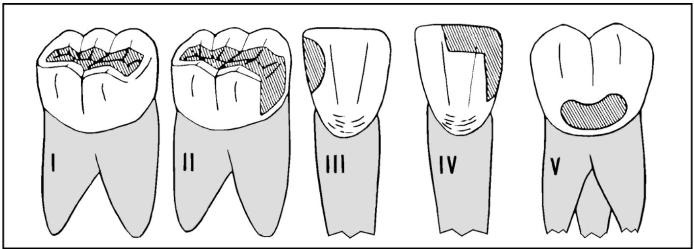
1.4.1. An inlay is a dental restoration that fits into a prepared cavity. It is held in place by its precision fit and by using a bonding composite methodor a cementing medium. Because inlays are, for the most part, surrounded by intact tooth structure, they are often called intracoronal restorations. The various forms of inlays are primarily used to restore individual tooth contours and function. In the majority of cases, an inlay is not a suitable anchor casting (retainer) for an FPD. Inlays are usually cast in medium hard gold, but they can be made of porcelain or acrylic resin. There are five classes of inlays, based on the location of the surfaces being restored (shown in Figure 1.1 and as follows):
1.4.1.1. Class I—Located on the occlusal surfaces of premolars or molars.
1.4.1.2. Class II—Located on an occlusal surface combined with one or both proximal surfaces.
1.4.1.3. Class III—Made for the mesial or distal surfaces of anterior teeth. This classification does not involve incisal angles.
1.4.1.4. Class IV—Made for the mesial and distal surface of an anterior tooth plus one or both of its incisal angles.
1.4.1.5. Class V—Limited to the facial surface of any of the teeth.
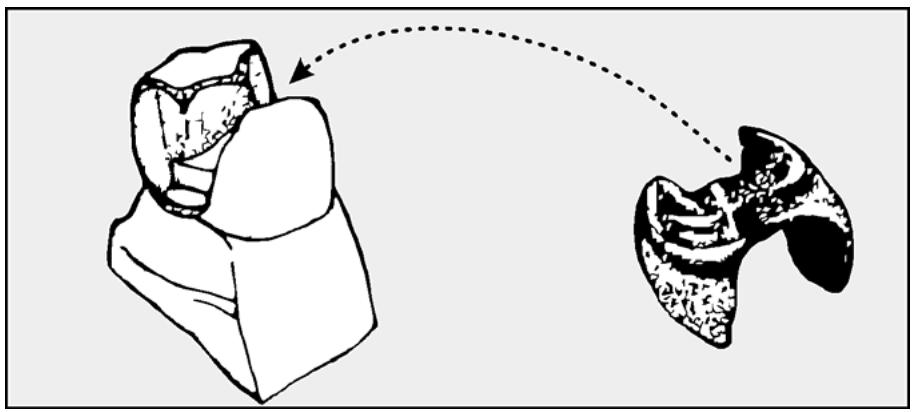
1.4.2. A more specific way of naming an inlay is to cite the tooth surfaces it restores. Examples include a disto-incisal (DI) inlay, mesio-inciso-distal (MID) inlay, mesio-occlusal (MO) inlay, and mesio-occluso-distal (MOD) inlay (shown in Figure 1.2).
Figure 1.1. Inlay Classifications.
text_image
Illustration showing five labeled teeth with shaded areas indicating specific regions, likely for dental or dental analysis.
Figure 1.2. MOD (Class II) Inlay.
natural_image
Diagram showing a mechanical component with a close-up of its internal structure, connected by a dotted line (no text or symbols present)
¶ 1.5. Pinledges
1.5.1. A pinledge is a thin, cast restoration that covers the lingual and one proximal surface of an anterior tooth. It is usually categorized as a specialized form of inlay. What distinguishes it from a conventional inlay is that it has two or three parallel pins, about 1.5 to 2 millimeters (mm) long, that penetrate the lingual dentin for retention. The thinness of the casting and the small diameter of the pins require that the pinledge be constructed of a hard, nonprecious metal or gold alloy (Type IV gold).
1.5.2. A modification to the preparation may be seen with resin-bonded FPDs. It is the least reliable of inlay restorations and potentially destructive to an abutment tooth. A pinledge functions best as filling for a cavity and should not ordinarily be expected to do more.
¶ 1.6. Onlays and Veneers
Onlay restorations are made from cast gold or ceramic materials that ordinarily cover the MOD surfaces of posterior teeth. On the anterior teeth, porcelain veneers may cover facial, incisal, and lingual surfaces. An onlay differs from an inlay in this respect. An onlay covers the entire occlusal surface of a tooth to include the cusps. An onlay is the smallest of the fixed prosthetic restorations classified as extracoronal. Whereas an intracoronal replacement like an inlay fits into a tooth, an extracoronal restoration fits around what remains of a tooth. For many dentists, an onlay is the minimum restoration adequate to act as a FPD retainer.
¶ 1.7. Artificial Crowns
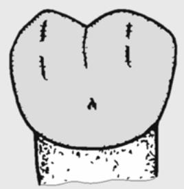
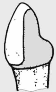
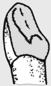
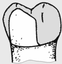
An artificial crown is a fixed prosthetic restoration that covers more than half of the tooth's surface exposed to view in the patient's mouth (Figure 1.3). Onlays are classified as extracoronal restoration, and the following kinds of crowns make up the balance of extracoronal category:
1.7.1. Complete Crown—Covers the entire surface anatomy of a tooth's clinical crown as follows.
1.7.1.1. Metal—Constructed entirely of a noncorrosive metal such as gold (Figure 1.3-A)
1.7.1.2. Veneered—A complete coverage; that is, a metal substructure overlaid with porcelain or resin for esthetic effect (Figure 1.3-B)
Figure 1.3. Some Types of Artificial Crowns.
natural_image
Simple line drawing of a heart-shaped object with four vertical lines and a small triangular shape on top, resting on a textured base (no text or symbols)
A. COMPLETE
METAL CROWN
natural_image
Simple line drawing of a stylized flower or seed shape with no text or symbols
B. VENEERED CROWN
natural_image
Simple line drawing of a tooth with no text or symbols
C. 3/4 PARTIAL CROWN
natural_image
Simple line drawing of a tooth with a shaded area, no text or symbols present
D. 7/8 PARTIAL CROWN
1.7.1.3. Jacket—A complete crown for an anterior tooth made entirely from porcelain or from acrylic resin.
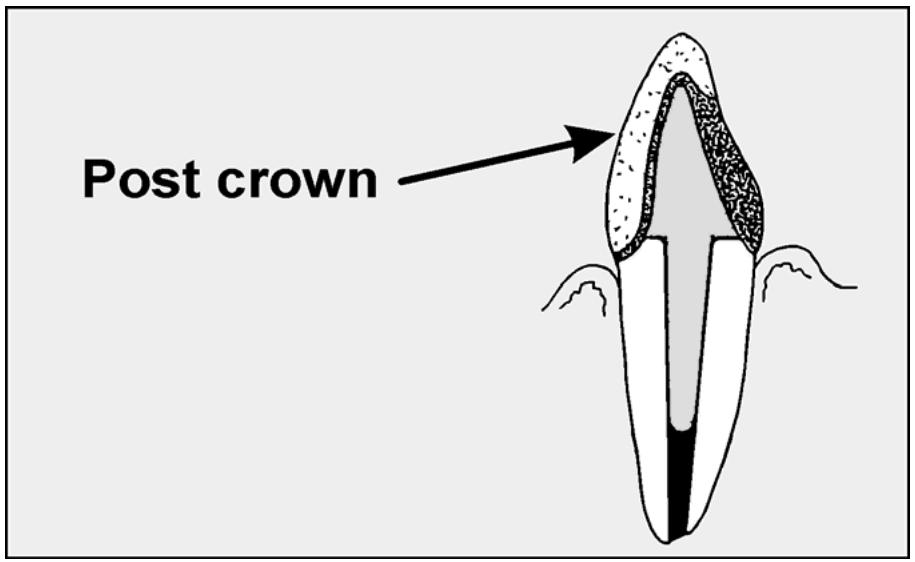
1.7.1.4. Post Crown—A complete crown of any kind (complete metal, veneer) supported by a metal extension (post) into a tooth's root canal. Endodontically treated teeth are teeth that have had the pulps removed and root canals filled. Such teeth eventually become brittle and are prone to fracture. In many instances, there is little coronal substance left and restorations continually come loose from them. To maintain an endodontically treated tooth as an abutment capable of supporting and retaining a crown, it is common practice to cement a post about 2/3 of the way into a root canal. The part of the post that protrudes from the root canal is called the core. Combined with the remains of the coronal part of the tooth, the core, is built to resemble a complete crown preparation. After the post and core are cemented into the root, a complete crown is fabricated on top of this foundation (Figure 1.4).
1.7.2. Partial Crown—Made entirely from metal that covers more than half, but less than the entire tooth's clinical crown. A partial crown is named according to the fractional amount of the clinical crown it covers. Examples include half, three-quarters (Figure 1.3-C), four-fifths, and seven-eighths crowns (Figure 1.3-D).
¶ 1.8. Fixed Partial Denture (FPD)
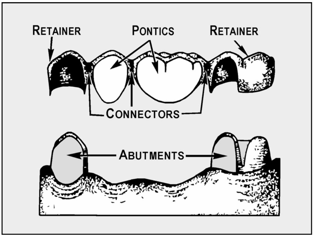
An FPD is a restoration designed to replace one or more missing natural teeth. In contrast to a removable partial denture (RPD), the dentist attaches an FPD tonatural teeth, roots, or implants by cementation or screws. A primary abutment is a tooth or root used for support and anchorage of one of the ends of an FPD. An intermediate abutment is a tooth without other natural teeth in proximal contact, situated between two primary abutments. The typical FPD consists of the parts shown in Figure 1.5 and as follows:
Figure 1.4. Post Crown.
text_image
Post crown
Figure 1.5. Parts of a Typical FPD.
text_image
RETAINER
PONTICS
RETAINER
CONNECTORS
ABUTMENTS
1.8.1. Retainers. A retainer is a casting the dentist attaches to an abutment tooth to secure and support the FPD's artificial tooth or teeth.
1.8.2. Pontics. Pontic is the general name for any artificial tooth suspended from a retainer. Pontics are classified according to the kinds of materials used to make them and according to the way they relate to gingival tissue under them (gingival adaptation), as follows:
1.8.2.1. Classification of Pontics Based on Materials Used in Construction.
1.8.2.1.1. Complete Metal Pontic. Use of these pontics is limited to the posterior areas of the mouth where they are not likely to be seen.
1.8.2.1.2. Cast Metal Combined With Prefabricated Resin or Porcelain Blank. Blanks are commercially available in anterior and posterior tooth forms and in a selection of sizes and shades. The dentist selects the appropriate blank and custom grinds it to fit an endentulous space. The rest of the artificial tooth, whether a backing for an anterior or an occlusal surface for a posterior, is waxed and cast in metal. The dentist then cements the modified resin or porcelain blank to its retaining post on the metal casting. Figure 1.6 shows types of prefabricated pontics and backings.
Figure 1.6. Prefabricated Pontics and Backings.
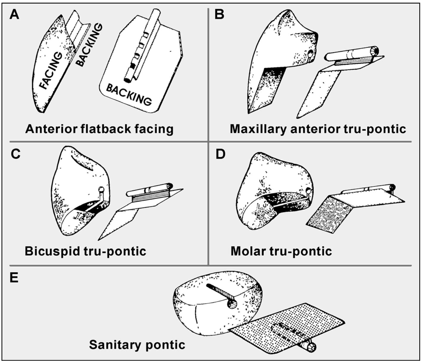
1.8.2.1.3. Veneered Pontic. The majority of the pontic's substructure is cast metal; the balance consists of a layer of acrylic resin or porcelain processed onto it. Acrylic veneers are mechanically retained by incorporating retention beads or loops into the casting. Porcelain is retained by baking and fusing it directly to the metal substructure. The tip of a pontic is usually made to contact gingival tissue. If the part of a pontic contacting the gingiva is made from a material that is chemically active or collects debris, inflammation will probably result. Glazed porcelain and highly polished gold provoke minimal tissue reaction. Acrylic resin is second best. Food tends to stick more to a plastic surface, bacteria grow in the debris, and produce toxic products that irritate tissue. In time, resin will absorb oral fluids and acquire an unpleasant odor.
1.8.2.2. Classification of Pontics Based on Gingival Adaptation. (NOTE: Paragraph 1.64 contains a detailed description of these pontics.)
1.8.2.2.1. Modified ridgelap pontic.
1.8.2.2.2. “Egg” shaped in contact with a residual ridge.
1.8.2.2.3. Hygienic (conventional or modified)
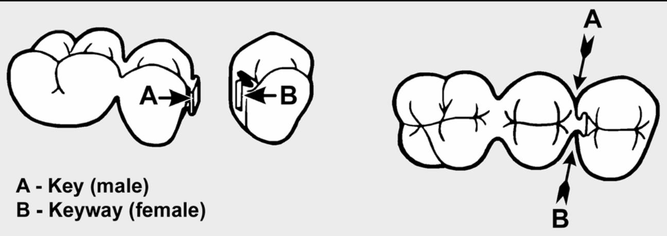
1.8.3. Connectors. A connector is that part of an FPD that unites a pontic to a retainer or joins pontics together. Connectors are classified as rigid (soldered joint) or nonrigid (key-to-keyway arrangements known as semiprecision attachments). The term stress breaker is commonly applied tononrigid connectors (Figure 1.7). Rigid connectors are by far the most popular option. There are problemsituations where a stress-broken FPD is the restoration of choice. A stress-broken joint is indicated when there is no common path of insertion for the retainers or when an FPD includes an intermediate abutment.
Figure 1.7. Nonrigid Connector.
¶ 1.9. Fixed Splints
1.9.1. There are ways to make a number of teeth share the load being placed on one of them to help prolong the life of teeth that are loose or have lost supporting bone.
1.9.2. Stabilizing a mobile tooth or teeth is called splinting. When stabilizing a tooth from adjacent, connected castings that have been cemented to place in the mouth, it becomes a form of fixed splinting. Such splints are made the same as an FPD. The only difference is that there are no pontics involved.
1.9.3. The overall size of FPDs and fixed splints is expressed in units. Each replacement tooth or retainer counts as a unit. For example, an FPD with three retainers and two pontics has five units; a fixed splint with four castings has four units.
¶ 1.10. Interim FPD
This is a rigid, provisional restoration that replaces missing teeth and is generally made from self-curing resin. Its purpose is to protect cut tooth surfaces and hold the abutment teeth in position while the definitive FPD is being made.
¶ Section 1C — Fixed Cast Restoration
¶ 1.11. Procedural Overview
Production of a fixed cast restoration usually progresses as follows:
1.11.1. The dentist determines a patient requires prosthodontic treatment and makes preliminary maxillary and mandibular impressions.
1.11.2. The technician first pours the diagnostic casts and makes custom trays if requested. Frequently, the diagnostic cast is also used to prepare a diagnostic wax-up to determine occlusal and esthetic requirements and also to construct provisional restorations or protheses.
1.11.3. The dentist prepares the natural teeth in the patient's mouth.
1.11.4. Using the custom tray, the dentist makes a final impression. If a need is apparent, the dentist will make a jaw relationship record. He or she then cements the interim fixed replacement in place with a weak cementing medium.
1.11.5. After receiving the final impression, the technician.
1.11.5.1. Fabricates dies and master (working) casts.
1.11.5.2. Mounts maxillary and mandibular casts in an articulator.
1.11.5.3. Adapts wax to dies and builds contours to harmonize and function with natural teeth.
1.11.5.4. Sprues, invests, and casts the wax pattern.
1.11.5.5. Joins the units by soldering if necessary.
1.11.5.6. Gives the restoration a preliminary surface finish.
1.11.5.7. Applies porcelain or resin veneers at this time or after the final adjustments to the prosthesis have been made in the patient's mouth.
1.11.6. The dentist tests the prosthesis in the patient's mouth and makes occlusion and margin adjustments. If many prosthetic units are involved, the dentist may send the case back to the laboratory for remount and adjustment of the occlusion in an articulator. The dentist furnishes another jaw relationship record if remount is necessary.
1.11.7. The technician final-finishes and polishes the restoration.
1.11.8. The dentist cements the completed restoration into place.
¶ Section 1D — Occlusion Factors Pertaining to Fixed Prosthodontics
¶ 1.12. Increasing Occlusal Stability
Many factors can improve the occlusal and functional stability of natural and prosthodontic teeth. Such factors include:
1.12.1. Balanced Centric Contact. The teeth close into maximum intercuspation (MI) at the end of each swallowing cycle. This occurs several thousand times each day formost people. Obviously, simultaneous and even contact ofall stamp cusps must occur at the moment of closure into MI if maximum stability is to be achieved. Two factors that can prevent balanced centric contact are uneven cusp height and inaccurate cusp placement, as follows:
1.12.1.1. Uneven Cusp Height. Uneven cusp height causes overloading and possible damage
to teeth that come into contact sooner or more heavily than others. It may also cause lightly loaded teeth to overerupt into positions that upset the centric and eccentric relationships that have been developed.
1.12.1.2. Inaccurate Cusp Placement. Inaccurate cusp placement causes a hit-and-slide contact pattern. This can result in occlusal forces not in line with the long axis, early wear, and instability of the teeth involved. It may also cause the patient to develop the destructive habit of bruxism.
1.12.2. Uniform Centric Contact. All of the posterior teeth contact exactly at the same time and with uniform pressure when the jaw is closed in MI. Nonuniform contact may be either anteroposterior with heavy molar or premolar contact, or cross-arch with one side hitting ahead of the other. In either case, the following adverse conditions could result:
1.12.2.1. Heavy Contact. The teeth in heavy contact would carry all of the pressure and be overloaded. Such pressures would probably not be in line with the long axis, and therefore would cause adverse occlusal leverages and forces.
1.12.2.2. Teeth Not In Contact. The teeth not in occlusion would tend to erupt into contact, thereby creating occlusal instability. Also, as they erupt into occlusion, they may cause a deflected malocclusion in the excu- rsive movements, a situation that would create adverse leverages and wear.
1.12.2.3. Involvement of the Temporomandibular Joint. The natural condylar guidance of the temporomandibular joint can be overpowered by inharmonious occlusal contacts. This can cause uneven loading and painful and possibly damaging stress on the tissues of the temporomandibular joint.
1.12.3. Forces Directed In Line With the Long Axis of the Teeth. The uniform centric contacts should be directed in line with the long axis of the teeth from a mechanical leverage standpoint. Ideally, tippedor tilted teeth should bestraightenedorthodontically.
1.12.4. Tripodism. For dental purposes, tripodism means each cusp contact should be a three-point contact, rather than a single-point, contact system of occlusion. The actual cusp tip should never contact anything at any time, anywhere. Rather, the ridges around the cusp tip should contact the ridges forming the fossa of the opposing tooth. Tripodism is encouraged as a system of occlusion for use in the fabrication of crowns and FPDs for following reasons:
1.12.4.1. To Establish Stability. Because it is very much like a three-legged stool (as opposed to a one-, two-, or four-legged stool), tripodism is considered to be a very stable system of occlusion.
1.12.4.2. To Maintain Stability. Relying on single-point contacts on a premolar, for example, gives only four connecting points for stability; that is, two stamp cusps contacting two fossae. Missing only one pair of these contacts causes a significant loss of stability. With tripodism, 12 pinpoint areas of contact are developed so a loss of contact between one or two pairs does not greatly reduce stability.
1.12.4.3. To Distribute Forces. Tripodism creates many pinpoint-type contacts rather than a few large areas of contact. Therefore, it produces a better distribution of the applied force.
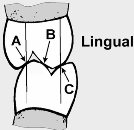
1.12.4.4. To Avoid a “Locked” Bite. A study of natural, unworn tooth anatomy indicates cusp ridges are convex. This makes it impossible for the tip of a cusp to contact the center of a fossa without creating a “locked” bite. The tripod type of contact is one answer to an “unlocked” occlusion. It permits lateral excursive movements to be made with a minimum of locking
effect. Think of this type of contact as a ball-bearing resting in the fossa, rather than the intermeshing of precision gears (Figure 1.8).
1.12.5. Twin Centric Contact (Cross-Tooth Stability). The stamp cusps are the buccal cusps of the mandibular teeth as they contact the fossa of the opposing maxillary teeth, and they are the lingual cusps of the maxillary teeth as they contact the fossa of the mandibular. Both groups of stamp cusps must occlude evenly and simultaneously. This cross-tooth contact (or twin buccolingual cusp contact) is essential for the following reasons:
Figure 1.8. Avoiding a “Locked” Bite.
Buccal
text_image
A
B
C
Lingual
Tripod contacts at points A, B, and C
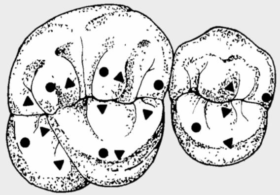
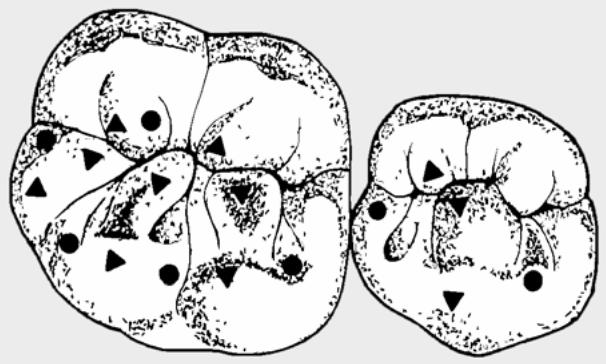
1.12.5.1. It Improves the Stability of Tripodism. Twin centric contact is essential to maintaining the many contact points established by tripodism (Figure 1.9).
Figure 1.9. Centric Contact Points (Closure Stoppers and Equalizers).
natural_image
Illustration of two abstract biological or geological structures with scattered markers (no text or symbols)
● Closure Stoppers
natural_image
Two abstract diagrams showing internal patterns with geometric shapes (triangles, circles, dots) and no visible text or symbols
▲ Equalizers
1.12.5.2. It Eliminates Damaging Contacts. If the lingual stamp cusp of the maxillary tooth does not contact the central fossa of the opposing mandibular tooth, the tendency exists for the maxillary tooth to erupt in a tilted pattern until that cusp does make contact. As shown in Figure 1.8, the occlusal forces are centered over the long axis of the teeth when the A, B, and C areas are all in contact. If you lose the B contact, the resulting forces of A and C would tend to displace the mandibular tooth lingually or the maxillary tooth buccally. If this occurs, the overerupted lingual cusp could constitute a heavy balancing side contact during lateral excursive movements. The result would be instability and a heavy balancing contact recognized as the most detrimental tooth contact possible (Class II Lever System).
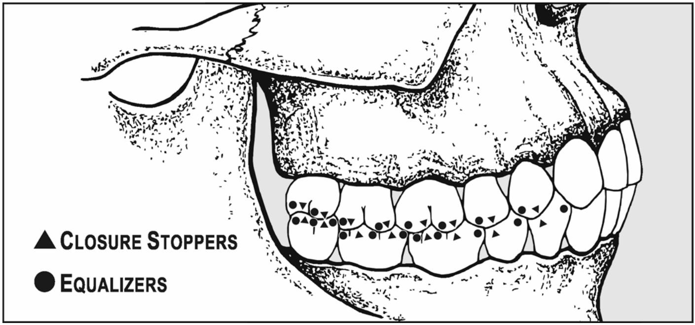
1.12.6. Closure Stoppers and Equalizers (Figure 1.10)
A, B, and C interocclusal contacts (shown in Figure 1.8) are as also designated as being either closure stoppers or equalizers. Closure stoppers and equalizers stop the closure of the mandible and equalize the forces to prevent buccal or lingual and mesial or distal movement of the posterior teeth, as follows:
Figure 1.10. Location of Closure Stoppers and Equalizers (Sagittal View).
text_image
▲ CLOSURE STOPPERS
● EQUALIZERS
1.12.6.1. Closure Stoppers. Closure stoppers stop the hinge closure of the mandible as it centrally relates to the maxilla. They also offset or neutralize the forces exerted by equalizers. Closure stoppers are located on the distal inclines of maxillary posterior teeth andon the mesial inclines of mandibular posterior teeth, primarily on marginal ridges. However, they can also be located on triangular, supplemental, or central ridges.
1.12.6.2. Equalizers. Equalizers offset (equalize) the forces exerted by closure stoppers, gaining mesial-distal stability. Equalizers also ensure buccal-lingual stability. They are located on the mesial inclines of maxillary posterior teeth and in the distal incline s of mandibular posterior teeth. They are primarily located on triangular, supplemental, and central ridges. Only rarely are they located on marginal ridges.
1.12.7. Limited Occlusal Table Width. The buccolingual width of prosthodontic teeth, especially of crowns or units of FPDs, must never exceed the width of the natural tooth structure they replace. In most cases, whether fabricating a single unit restoration or a long span FPD, the buccolingual width must be made the same width or narrower than the original teeth. This is true for the following reasons:
1.12.7.1. Increased Occlusal Load. Increasing the occlusal table width directly increases the surface area of a crown or FTD. Increasing the surface area during the chewing cycle increases the area of opposition to occlusal forces and adds directly to the functional load applied to abutment teeth. Increasing the functional load puts additional stress on the root systems of abutment teeth. This stress often results in a loss of periodontal support and increasing mobility of the abutment teeth.
1.12.7.2. Forces Not In Line With the Long Axis. Increasing the occlusal width puts occlusal stresses further from the long axis of abutment teeth. This increases the leverage forces felt by the root system of the abutment tooth. It can also lead to a loss of periodontal support and mobility of the teeth under stress.
¶ Section 1E — Diagnostic Casts, Interim Fixed Prostheses, and Custom Trays
¶ 1.13. Preliminary Impressions and Diagnostic Casts
1.13.1. Because of natural toothand soft tissue undercuts, elastic impression materials are used for fixed prosthodontic impressions. Ir reversible hydrocollo id (alginate) is the material used formaking preliminary impressions.
1.13.2. Diagnostic casts are poured from preliminary impressions made in stock trays. In complete denture and RPD work, diagnostic casts are used for evaluating the patient's problems and for constructing a custom tray. A diagnostic cast has additional value in fixed prosthodontic treatment procedures—it is frequently used formaking interim (provisional) fixed restorations.
1.13.3. For a more detailed description of the care and pouring of alginate impressions and trimming specifications of casts, consult the following sections or paragraphs in Volume 1 of this pamphlet.
1.13.3.1. Paragraph 2.40, Hydrocolloids.
1.13.3.2. Section 7C, General Rules for Pouring, Trimming, and Handling Casts.
1.13.3.3. Paragraph 7.24, Preliminary Impressions; paragraph 7.25, Two-Step Pouring of Diagnostic Casts; and paragraph 7.26, One-Step Pouring of Casts.
¶ 1.14. Interim (Provisional) Fixed Restorations
Provisional resin restorations, made with the indirect method, are routinely constructed for onlay, crown, and FPD situations. The diagnostic cast is a major aid in making these prostheses. So me technicians then use the more accurate first cast to make the interim restoration. Once the cast is made, there are a number of ways to either make, or help the dentist make, an interim fixed prosthesis. It is helpful to mount the cast in a simple, fixed-guide articulator that will hold the casts in MI. Index the casts and paint the bases with separator before mounting them. The following methods can be used to make interim restorations:
1.14.1. Vacuum-Forming Methods. To begin, you must have access to a vacuum-forming machine and the proper kindof therm oplastic material (Clear Temporary Splint Material, 0.020 inch, Buffalo Mfg Co). Then follow the procedures in Method #1 or #2 below:
1.14.1.1. Method #1.
1.14.1.1.1. If the teeth the dentist intends to prepare are broken down, complete a diagnostic wax-up to restore tooth form and function. Duplicate this wax-up in dental stone and then make a clear matrix for the interim restoration. If the provisional prosthesis is for a proposed FPD site, also adapt mismatched, uncarded resin denture teeth to the edentulous space and adjust the occlusion.
1.14.1.1.2. Take the cast offits mounting and vacuum-form the clear splint material over the cast. Cut out the part of the formed plastic that includes the region of the fixed prosthesis PLUS one or two uninvolved teethanterior and posterior to it.
1.14.1.1.3. Give the clear plastic template to the dentist to use as a mold to form a self-curing, provisional prosthesis in the patient's mouth. (Uninvolved teeth are a part of the template so they can act as a seating index.)
1.14.1.2. Method #2.
1.14.1.2.1. Produce a template as described in Method #1.
1.14.1.2.2. Remove any denture teeth used to fill edentulous areas and save them for reuse on other cases.
1.14.1.2.3. Carefully shave away about 1 mm of dental stone from each coronal surface of the cast that corresponds to the tooth surface the dentist in tends to prepare (Figure 1.11). Remove enough of the occlusal and axial surfaces to eliminate all undercut areas. Feather the axial reductions to a knife edge at the crest of the gingival margin. Apply tinfoil substitute to the parts of the cast the template covers.
Figure 1.11. Vacuum-Forming Method for Interim Prostheses.
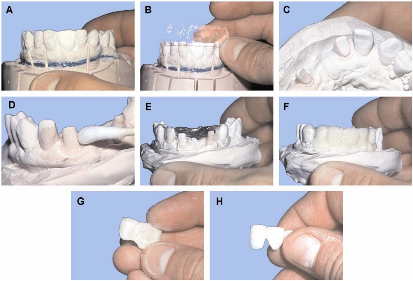
1.14.1.2.4. Place a fluid mix of tooth-colored resin in the template. Self-curing resin as well as light cured resin will work for the interim prosthesis. Seat the template on the cast and hold it there until polymerization begins.
1.14.1.2.5. To accelerate polymerization and to help reduce porosity, cure the resin according to the manufacturer's recommendations.
1.14.1.2.6. After curing is complete, remove the template from the interim prosthesis. Place the cast on its mounting in the articulator and adjust the occlusion.
1.14.1.2.7. Take the prosthesis off the cast. Finish and polish it, being careful to preserve the anatomical contours of the occlusal and axial surfaces.
1.14.1.2.8. Disinfect and place the provisional prosthesis in a plastic bag with a moist cotton roll for delivery to the dentist.
1.14.2. Alternative Methods. You should also be aware of the following alternatives to vacuum-forming a template when the equipment required for that technique is not available: (NOTE: In any alternative method chosen, the problem focuses around making a template.)
1.14.2.1. Alginate Impression Template Method. In the vacuum-forming technique, tooth defects were filled with dental stone, resin denture teeth were adapted to edentulous spaces, and relatively heat resistant materials were used because hot plastic was going to be sucked down over the cast. In the alginate impression method, there is norequi rement for intense heating of the template material.
1.14.2.1.1. Fill intooth defects with a white inlay wax and provide replacement teeth for the edentulous spaces.
1.14.2.1.2. Soak the cast in saturated calcium sulphate dihydrate solution (SDS) for 5 minutes.
1.14.2.1.3. Take a stock, rim-lock tray and make an alginate impression of the cast. Cut back excess alginate to the borders of the tray.
1.14.2.1.4. Remove any tooth replacements from the edentulous spaces. Shave the occlusal, incisal, and axial surfaces of the teeth the dentist will prepare. Follow directions given in Method #2 (paragraph 1.14.1.2). Paint the cast with a tinfoil substitute.
1.14.2.1.5. Cut a small, V-shaped wedge out of the sidewall of the impression. This channel should lead from the edge of the tray into the bulkiest part of the provisional prosthesis. The channel will serve as an escape route for excess acrylic resin.
1.14.2.1.6. Prepare a fluid mix of tooth-colored autopolymerizing resin and flow it into the appropriate part of the alginate impression. Wait for the resin surface to lose its gloss and seat the impression on the cast.
1.14.2.1.7. For the remainder of the procedure, follow directions in Method #2, paragraphs 1.14.1.2.5 through 1.14.1.2.8.
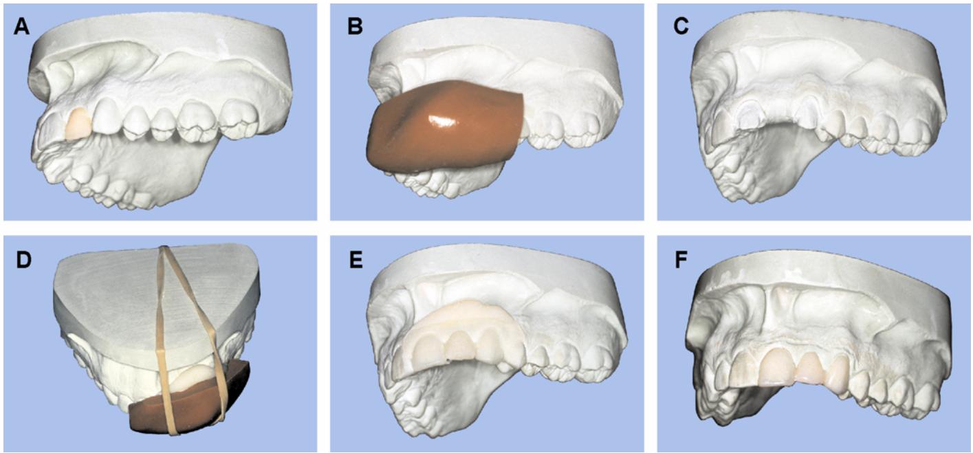
1.14.2.2. Silicone Template Method (Figure 1.12)
1.14.2.2.1. Use white inlay wax to correct defects in all the teeth the dentist is going to prepare and form replacements for the missing teeth. Use old, uncarde resin denture teeth as natural tooth substitutes if they are available.
1.14.2.2.2. Mix the silicone impression material and adapt it over the region of the fixed prosthesis, to include at least one uninvolved toothanterior and posterior to it. The template should be 6 to 8 mm thick to provide adequate stability. After the material has set remove the template and trimany excess material.
1.14.2.2.3. Remove any tooth replacements from the edentulous spaces. Shave the occlusal, incisal, and axial surfaces of the teeth the dentist will prepare. Follow directions given in Method #2 (paragraph 1.14.1.2.3). Apply a tinfoil substitute to the parts of the cast the template covers.
1.14.2.2.4. Mix tooth-colored, self-curing acrylic resin in a glass jar as directed by the manufacturer. Wait for the early dough stage and pack a slight excess of resin into the template. Seat the tem plate on the cast. Use a small rubber band to hold the tem plate and cast together during the curing of the acrylic resin.
1.14.2.2.5. For the remainder of the procedure, follow directions in Method #2, paragraphs 1.14.1.2.5 through 1.14.1.2.8.
Figure 1.12. Silicone Template Method for Interim FPDs.
¶ 1.15. Custom Trays
1.15.1. In fixed prosthetic dentistry, custom trays are used almost entirely withelastomeric impression materials (Figure 1.13)
For the elastomers toregister an impression accurately and show acceptable elastic behavior, it has to have adequate thickness. This is why custom trays are routinely made over spacers.
1.15.2. It is one thing to create space, but quite another to maintain it. To guaranteeth at the tray is being heldout of contact with the dentist's tooth preparations by a measurement at least equal to the thickness of the spacer, stops are incorporated into the tissue side of the tray. Maxillary custom trays are made with a single, large, palatal stop. Occasionally, however, stops are placed ontooth surfaces. In the mandibular arch, the occlusal and incisal surfaces of teeth are the only solid places for stops to hit. Such stop contacts are undesirable, but unavoidable. Stops are NE VER placedover teeth the dentist intends to prepare.
1.15.3. Custom trays can be made with self-curing resin, vacuum-forming material (0.125 inch), or light-cured acrylic resin. Because the dentist has to exert considerable force on the handle of the tray, be sure to make it strong enough. Mold and trim the custom tray according to directions given in Volume 1, Section 7E, but note the following differences in spacer requirements:
Figure 1.13. Maxillary and Mandibular Acrylic Resin Custom Trays.
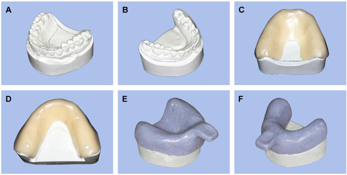
1.15.3.1. Self-Curing Acrylic Resin and Light-Cured Trays. Block out facial and lingual soft tissue undercuts with baseplate wax. Adapt two sheets of baseplate wax to cast. Cut the borders of the wax to match the tray's outline as drawn by the dentist. (See Figure 1.13-D for suggested placement of stops.) Form the tray in self-cur-ing resin. Trim the borders back to d esign and roundoff the edges. If the wax spacer is to peel out of a resin tray cleanly, polymerization has to be complete and the plastic must be cool. One way to make sure wax does not stick to the tissue surface of the tray is to adapt tinfoil over the spacer before molding the resin. Another way is to substitute a sheet of plastic film for the tinfoil.
1.15.3.2. Vacuum-Forming Trays. The shape and thickness of a maxillary or mandibular arch spacer for a vacuum-forming tray is the same as for an acrylic resin tray. The important difference is that wet tissue is substituted for the wax. NOTE: Rubber base impressions can be very difficult to remove from the patient's mouth.
¶ Section 1F — Dies and Working Casts
¶ 1.16. Overview
1.16.1. A working cast is a cast used to duplicate the patient's prepared tooth (teeth), the other teeth present in the arch, and all as sociated soft tissue structures. It is used to establish the shape, proximal contacts, occlusion, and fit of fixed prostheses, from the simplest inlay to the most complicated complete mouth rehabilitation.
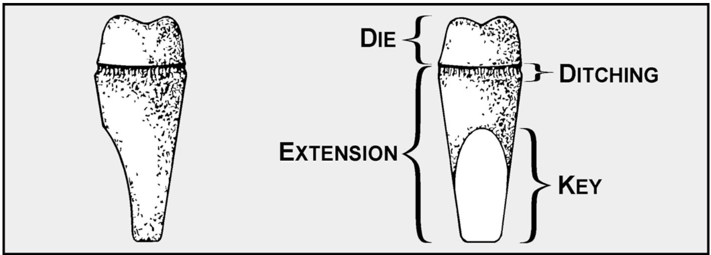
1.16.2. A die is a positive reproduction of the prepared portion of a tooth in a hard, stable material such as improved stone, dental am algam, acrylic resin, epoxy resin, or el ectrodeposits of metal. Dies are composed of two parts, the duplicate of the prepared toothand an extension (Figure 1.14). By itself, a die has limited value until its relationship with adjacent and opposing teeth is established.
Figure 1.14. Improved Stone Die Made From a Tube Impression.
text_image
DIE
EXTENSION
DITCHING
KEY
1.16.3. A working cast contains one or more dies. Dies are either part of a working cast or they are not. For those dies that are not, the extension is a convenient grip and nothing more. Dies that are part of a working cast are frequently made to be removable, and their extensions are keyed in some manner. Because of the key, the die will not rotate and it can be placed back in the cast in the same position after every removal. Dies can be keyed in a variety of ways; for example, carve facets on the extension or make the extension from a commercially available, metal dowel pin (paragraph 1.20.2).
¶ 1.17. Individual Dies Made From Tube Impressions
1.17.1. The dentist has access to a stock of short metal tubes or bands that are made from copper or aluminum. He or she can use these bands as miniature trays to make impressions of single teeth. Rubber base and modeling plastic are the impression materials most often employed. Dies derived from tube impressions can be keyed and subsequently incorporated into a working cast. Tube impressions are most frequently poured in improved stone.
1.17.2. Because tubes made from copper or aluminum bend easily, the tube impression should be handled gently. Rinse the impression with room temperature water torid it of saliva and debris and dry it with gentle blasts of compressed air.
1.17.3. “Box” the rim of the band with 28-gauge sheet wax or cellophane tape. The boxing material should be wide enough to produce an extension that is 2.5 centimeters (cm) long after the impression is poured. When using wax, seal the “box” at the side lap and at the junction with the band. Be careful not to heat the impression material.
1.17.4. Mix a sufficient volume of die stone according to the manufacturer's directions. The water-to-powder ratio and the manner of spatulation will determine the hardness, density, and surface smoothness of the stone. When possible, use vacuum spatulation and mix the stone from 10 to 15 seconds. Avoid lengthy mixing because it causes the stone to set very rapidly.
1.17.5. Gently vibrate a small amount of the mix into the boxed impression until the deep parts are filled. Without trapping air, add more of the mix until the box is filled. Let the stone reach final set.
1.17.6. If the impression is made of nonelastic modeling compound, place the impression and die stone assembly in warm water at 140 °F for 3 to 5 minutes. When the modeling compound. becomes soft, extract the die. Failure to wait until the modeling compound softens may result in unacceptable die abrasion or outright breakage. If you are using an elastic material to make the impression, extract the die without applying heat to the impression material.
1.17.7. Trim the die's extension to a smootheven taper. If the die is going to become a removable die in a working cast, cut at least one flat facet on the extension portion to act as a key (Figure 1.14).
¶ 1.18. Removable Die Systems
There are a great variety of removable die systems; some are good andothers are poor. Besides ease of fabrication and subsequent convenient handling, the overriding requirement is that dies, once removed, have to go back to exactly the same place. Dies that do not satisfy this requirement have greatly diminished value. Paragraphs 1.19 through 1.26 describe these systems in detail.
¶ 1.19. Dowel Pin Systems
1.19.1. A working cast can be made with removable stone dies by pouring the arch portion of an impression first and then pouring the rest of the working cast around commercially fabricated die extensions (dowel pins)
1.19.2. One of the improved stones is used for both pours. Occasionally, the technician reproduces the dentition and prepared teeth in a working cast, using electrically deposited silver or epoxy resin. He or she then completes the cast, using improved stone and one of the conventional pinning techniques.
1.19.3. Keyed and tapered metal dowel pins with serra ted heads are used as die extensions. Dies having these keyed dowel pin extensions will travel to place and seat in a working cast in only oneway. Dowel pins can be placed in any kindof imp ression. The differences in techn ique focus on two points: (1) the way the dowel pins are held in position while the first pour of stone is setting, and (2) the way separation between the die and working cast is achieved.
1.19.4. Tooth preparation sites (dies) are not the only areas of an arch that are made removable with dowel pins. It is very common practice to make the unaltered teeth next to the dies removable. Contact areas on finished castings are better evaluated when this is done. Sometimes, the only way a die will come out of the base pour is to make adjacent teeth removable, to o. Making the edentulous ridge between two abutments removable has definite advantages in shaping and finishing FPD pontics.
1.19.5. A final impression for a fixed prosthesis may be made from elastomeric material or reversible hydrocolloid. Im pressions made withelastomeric impression materials have several advantages over those made with hydrocolloid. Elastomers are much less susceptible to temperature and humidity changes, and they are stronger than hydrocolloid. Two successive casts from the same elastomeric impression may be poured to make the second cast a duplicate of the first. However, if the impression is being made from reversible hydrocolloid, another impression will have to be made to pour a second cast.
1.19.6. See paragraphs 1.20 through 1.24 for various techniques and methods pertaining to this system.
¶ 1.20. Saw-Out Technique for Elastomeric Impressions
This technique is shown below and in Figure 1.15:
1.20.1. Rinse the rubber base final impression in room temperature water to flush away saliva and debris. Disinfect and carefully dry the impression with a gentle stream of air.
Figure 1.15. Dowel Pin Removable Dies (Saw-Out Technique).
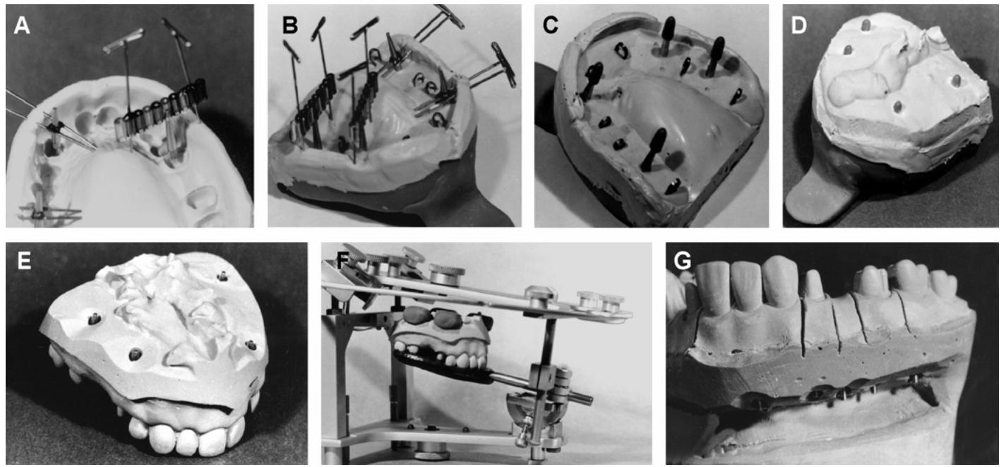
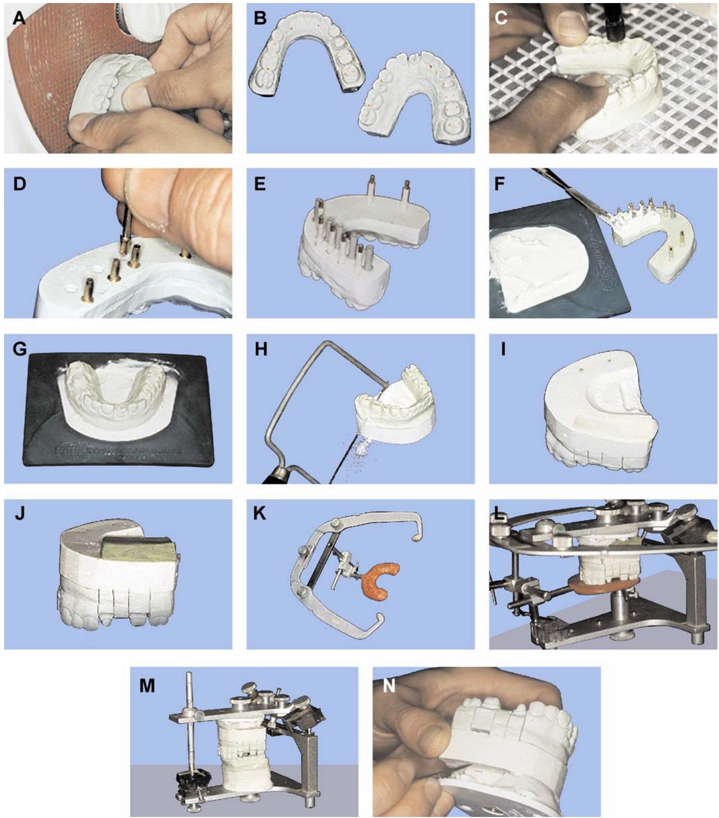
1.20.2. Above each preparation site and adjacent unprepared tooth (teeth), drive two straight pins from the buccal flange through to the lingual aspect of the impression. The distance between the straight pins should be a little greater than the width of a dowel pin. The thinner and sharper the straight pins, the lesser the chances of distorting the impression. The 28-gauge disposable injection needles work best (Figure 1.15-A)
1.20.3. Position a dowel pin between a set of two straight pins and centered above the cervical margin of the preparation site or tooth imprint, flat side to the distal and long axis of the dowel pin parallel to the long axis of the tooth's root. Besides being as parallel as possible to the long axis of the tooth's root, the dowel pins placed in adjacent areas should parallel each other. Neatly sticky wax the dowel pins to the straight pins. NOTE: A variation of this method is where the dowel pins are held in place by commercially available le plastic tubing bridged a cross vertically oriented straight pins. Dowel pins can also be held in place with bobby pins fastened to the impression with straight pins and sticky wax (Figure 1.15-A)
1.20.4. Pour the impression in two steps (stages)
The first stage takes in the tooth preparations, unaltered teeth, and edentulous areas (Figure 1.15-B and -C). Pour the second stage on top of the first and form the base of the cast (Figure 1.15-D). To prevent entrapment of air bubbles caused by the surface tension of the dental stone, use a wetting agent on the impression before flowing in the first stage.
1.20.5. Vacuum spatulate the die stone according to the manufacturer's directions. Starting in a heel area, vibrate the stone into the impression and make it run to the opposite side. Be careful not to trap bubbles. The depth of the first pour should come to a level slightly below the straight pins and sticky wax. Embed staples (washers, paper clips) into all segments of the first pour that are not programmed to be removable; that is, any part without a dowel pin. NOTE: Polysilox ane impression materials are extremely hydrophobic. Be fore pouring the impression, ensure that no moisture has collected in crevices, blocking out the fine detail.
1.20.6. After the first pour has reached final set, remove the straight pins and clean the sticky wax from around the dowel pins. At the place where the dowel pin enters the first pour, cut away the
flash of stone and create a butt junction. Cut two he mispherical indexing dimples into the base of each doweled part, one buccal and one lingual to the dowel pin. Use a #8 round bur. Do not sink the bur into the stone further than one-half the diameter of the bur head.
1.20.7. Apply a separator to the bases of the parts that contain dowel pins. If this is not done, the areas in the first stage that are programmed to be removable will not separate cleanly from the second stage.
1.20.8. Moisten the surface of the first pour and proceed to build a stone base for the working cast. Stack the stone to reach near the tips of the dowel pins without actually burying them. Do not attach balls of wax or clay to the dowel pin tips to act as pin locators. If wax or clay residues find their way into a dowel pinhole, a removable die will not seat. A better option is to place red plastic covers on the tips of the dowel pins (Figure 1.15-C and -D). Such covers are part of the
“placement kit, tooth” previously mentioned. If the plastic covers or something similar are not available, do not use anything.
1.20.9. Next, place retention nodules onto the stone surface so the working cast stays attached to an articulator mounting ring when mounting time comes (Figure 1.15-D). Place the handle of the tray into an appropriate holder and let the stone set, impression side up. NOTE: Casts sent to another laboratory for appliance fabrication must have smooth bases so they can be separated from their mountings and returned with the finished restoration.
1.20.10. Wait until the second pour reaches final set and separate the cast from the impressions (Figure 1.15-E)
NOTE: Polyether impression materials are very stiff, making separation of the cast from impressions difficult.
1.20.11. Next, trim the cast. The slush that splashes off a trimming wheel can ruin a working cast. If precautions are not taken, debris will cling to cast surfaces, making them rough and inaccurate. Before trimming a cast, soak it in SDS for about a minute. The slush will have fewer tendencies to stick. As additional protection, cover the cast's arch form with wet tissue paper. After trimming the cast, rinse it thoroughly in SDS. Blow it dry and set it aside for 30 minutes.
1.20.12. Clear any stone away from the tops of the pins, ensuring about 2 mm is exposed to view. If covers were used, remove them.
1.20.13. Before dies are sawed and tappedout for the first time, accurately seat the working cast in a jaw relationship record (Figure 1.15-F) and mount the working cast in an articulator (according to cast mounting procedures in Section 1G). Then proceed to the next stepin the current process.
1.20.14. Using a flat-bladed die saw or fine-bladed coping saw, extend cuts from the gingival crest areas mesial and distal to a preparation or dowel ed tooth, down to the junction be tween the first and second pours of the working cast. If a die does not have other removable segments adjacent to it, the two saw cuts should converge toward the base of the cast. If there are a number of consecutive dies and doweled teeth present, the most mesial and most distal cuts should converge toward the base of the cast and a ll in intermediate cuts should bisect the ang le made by the converging outer cuts (Figure 1.15-G)
1.20.15. With the castheld low over a table and crad led in the palm of the hand, exert downward pressure on the tip of a dowel pin with an flat instrument. The doweled area should pop loose. NOTE: Ne ver saw out dies or doweled teeth and pop them loose before the cast trimming procedure is done. Once removed, a die will not return to place if slurry from the trimming wheel gets into the dowel pinholes.
1.20.16. The next step is to trim the dies (paragraph 1.33.1)
¶ 1.21. Saw-Out Technique for Reversible Hydrocolloid Impressions
1.21.1. Review the procedures described in paragraph 1.20 for obtaining removable dies and a working cast from an elastomeric impression by the saw-out technique. This method is almost identical. It only differs in the way dowel pins are positioned because reversible hydrocolloid does not retain straight pins well, is weak, and splits easily.
1.21.2. Certain ingredients in some reversible hydrocolloid impression materials detrim entally affect the surface hardness of dental tone. To compensate for the problem, immerse the impression in a 2 percent solution of potassium sulfate for about 5 minutes before continuing. This is called “fixing.”
1.21.3. Using an indelible pencil, make marks buccal and lingual to preparation sites and adjacent teeth. The marks should be up high enough to still be visible after the first stage of the working cast has been poured.
1.21.4. Place a dowel pin in a bobby pin. The intent is for the dowel pinto hang into a preparation site or adjacent tooth imprint while suspended from the bobby pin. The buccal and lingual walls of the impression support the bobby pin. Align the dowel pins in the areas selected according to the manner described for rubber-base impressions. Sticky-wax the dowel pinto the bobby pin and lay the assembly aside.
1.21.5. Pour the first stage of the working cast. Using the indelible pencil marks as guides, position the dowel pin or bobby pin assemblies in their proper places. A dowel pin is parallel to the long axis of a toothand multiple and consecutive dowel pins are parallel to each other.
1.21.6. Let the stone of the first stag e reach final set. Remove the bobby pins and clean the sticky wax from the dowel pins. Prepare butt junctions where the dowel pins enter the first stage.
¶ 1.22. Matrix Band Shim Method
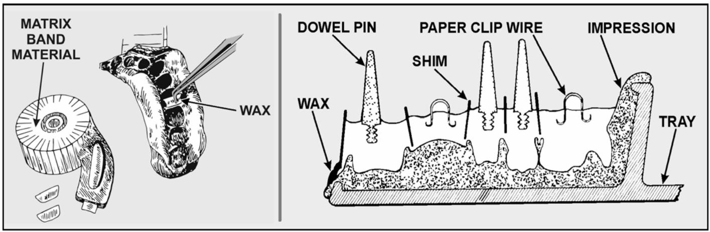
A saw can not be used to full advantage in an interproximal area where the preparations are too close to each other or to adjacent teeth. The shim method of making removable dies is helpful in these kinds of cases (Figure 1.16). Two-thousandths (2/1000) of an inch matrix band material can be used to separate adjacent dies from each other and from the rest of the dental arch in the first stage pour. After the second stage pour has set, the remove metal shims, which should almost eliminate the need for sawing. The matrix band material is available in 5/16- and 7/16-inch widths. Use the width that works best for a given situation.
Figure 1.16. Dowel Pin Removable Dies (Shim Method).
text_image
MATRIX
BAND
MATERIAL
WAX
DOWEL PIN
PAPER CLIP WIRE
SHIM
IMPRESSION
WAX
TRAY
1.22.1. Rubber-Base Impressions.
1.22.1.1. Cut trapezoid-shaped shims (dividers) from 2/1000 of an inch stainless steel matrix band material. Place these shims mesially and distally to a tooth preparation site or adjacent tooth imprint. Use only one shim in each interproximal area. The s hims, together with the sidewalls of the impressions, will form a “box” around each area of interest. Shape each shim to conform to the facial, lingual, and gingival contours of the impression without quite touching them. Be sure to allow about 1 mm of space between the impression of the proxi mal gingival crests and the band material. Lay aside the cut shims in their proper sequence to help in placing them accurately.
1.22.1.2. Carefully apply a 1 or 2 mm thickness of utility wax to the facial and lingual aspects of the impression above the imprints of prepared and adjacent teeth. Warm a shim in an open flame sufficient for it to melt the utility wax and go to place easily. Converge the shims apically on an isolated abutment. For multiple, adjacent doweled areas, the most mesial and distal shims in the segment should converge ap ically. All intermediate shims should bisect the angle made by the converging outer shims.
1.22.1.3. Position the dowel pins by using the straight pin or bobby pin methods described in paragraph 1.20. NOTE: Some technicians place dowel pins in soft stone “freehand” immediately after the first stage has been poured. This method can be used successfully, but the technician has minimum control over dowel pin alignment.
1.22.1.4. Minimize entrapment of air bubbles by using a surface tension reducing agent over the rubber base material. Pour a vacuum spatulated mix of die stone into the impression to produce the working cast's first stage. Leave about 0.5 mm of the shim tops visible. If the dowel pins were not previously positioned with straight pins, a lign them now. Provide mechanical retention in all segments of the first stage not destined to be removable. Use small washers, wire loops, or small nodules of stone.
1.22.1.5. After final set of the first stage, drill small indexing depressions to the buccal and lingual of a dowel pin with a #8 round bur. Paint a separator onto the bases of the doweled parts and pour the second stage of the working cast as previously described in paragraphs 1.20.8 through 1.20.10. Do not bury the ends of the dowel pins.
1.22.1.6. Trim the working cast, taking care not to get stone slush all over it. Mount the working cast and its opponent in an articulator (Section 1G).
1.22.1.7. Using a #0000 jeweler saw blade, carefully cut from a proximal gingival crest down to the shim. Remove each doweled part by pressing on the dowel pin and popping it out. To do this successfully, first expose the buccal, lingual, and gingival edges of the shims with a #25 knife blade.
1.22.2. Reversible Hydrocolloid Impressions.
1.22.2.1. Subm erge reversible hydr ocolloid impressions in a 2 percent potassium sulfate solution for about 5 minutes. This improves the surface hardness of the set stone.
1.22.2.2. In a rubber-base impression, undersized shims were waxed to place. In a reversible hydrocolloid impression, the shims are cut slightly oversized buccolingually so they can be embedded in the impression's sidewalls. To avoid distorting the impression, a shimshould clear the gingival crest proximally by about 1 mm.
1.22.2.3. The rest of the technique is the same as described in paragraph 1.22.1.
¶ 1.23. Pindex Instrument and Technique
1.23.1. The Pindex instrument or similar drilling device simplifies paralleling and centering dowel pins for removable stone dies made in elastomeric or hydrocolloid impressions (Figure 1.17). This technique is useful when it is more advantageous to pin the die after the first pour is complete. Such is the case in a difficult-to-pin hydrocolloid impression or when an epoxy resin technique of cast construction is used.
1.23.2. Make the first stage pour sufficiently thick—at least 15 mm from the bottom to the marginal extension. Carefully remove the arch from the impression and trim the base against a cast trimmer to create a flat surface (Figure 1.17-A). The finished first stage pour should be 15 mm from the base to marginal extension. The first stage pour should be slightly damp before drilling the pinholes (Figure 1.17-B).
1.23.3. Using a pencil, plot each pin hole location on the surface of the first stage pour. Drill two holes, one buccal and the other lingual, centered on each prepared posterior tooth (Figure 1.17-C). Ensure the holes are farenough apar t that they won't interfere with seating of the plastic sleeves that cover each pin. Drill one hole lingual to each prepared anterior tooth. Drill individual pinholes in adjacent areas that will be removable or used for placing reten tive devices. After all holes are drilled, use compressed air to clean any debris from the holes.
1.23.4. Select the proper pin for each location and cement it in place with cyanoacrylate glu e (Figure 1.17-D)
Place the corresponding plastic or metal sleeve over the metal pin (Figure 1.17-E). Regular brass dowel pins with the tapered end bent over can be used for retention areas. Use the dual pin with corresponding metal sleeves for anterior s to compensate for narrow arch sizes. Use this pin without the metal sleeve if space is limited. When using the dual pin, make a small indexing notch lingual to each hole with a separating disc. Use the long pin with a white plastic sleeve as a dowel pin for posterior teeth. Use the short pin and gray sleeve with the long pins for indexing the die.
1.23.5. Paint a separator on the base ofall areas you intend to saw out. Before constructing the second stage, place a strip of utility wax over the pin extensions to access the pins and to close over the opening of the gray sleeves. Bead and box the first pour with wax or use the rubber molds to form the base. Moisten the surface of the first pour before filling the mold to form the base. Be sure to flow stone in and around the sleeves before inverting the arch into the stone-filled base mold (Figure 1.17-F and -G).
1.23.6. Trim the cast and section the dies as previously described (Figure 1.17-H through -J)
¶ 1.24. Silver-Plating Polysulfide and Silicone Impressions
1.24.1. Electroplated dies have the following advantages over other die materials. harder surfaces, more abrasion resistance, and generally superior surface detail. These advantages make electroplated dies an excellent choice for use in making porcelain restorations. NOTE: Tox ic fumes produced by the silver cyanide solution are extremely dangerous. Use the solution under an exhaust hood. Although it is possible to silver-pla te silicone impressions, distortion can be a problem. Do not attempt to plate polyether impressions.
1.24.2. Thoroughly clean and dry the impression because the metalizing powder will not adhere to wet surfaces and tends to collect in corners.
1.24.3. Insert the cathode wire through the impression in the buccal sulcus area and fix it firmly in place to prevent twisting and loss of contact with the impression material.
Figure 1.17. Dowel Pin Removable Dies (Pindex Method).
1.24.4. Paint the surface of the area to be plated with silver powder. Avoid excess pools of silver powder in the impression and ensure the wire makes contact with the powder. Pay close attention to undercut areas, making sure they are adequately covered. Dust away all surplus powder and lightly dry the impression with compressed air. You may also use commercially available aerosol silver sprays.
1.24.5. Fill the preparations and the teeth with the electrolytic solution by using an eyedropper to prevent air bubbles and resulting voids.
1.24.6. Completely submerge the impression in the plating solution. Attach the cathode wire to the negative side of the unit and connect the anode of pure silver to the positive side. Switch on the plating unit and adjust the output for a complete arch impression to approximately 150 (mA) or less for smaller sections. After 1 hour of plating, inspect the impression and even deposition of metal to ensure there are no voids. If voids are present, remetalize those areas with silver powder and resume plating.
1.24.7. Remove the plated impression after approximately 15 hours and wash it thoroughly under running water. Dry the impression, using compressed air.
1.24.8. Pin and pour the impression as you normally would.
¶ 1.25. Removable Dies and a Working Cast Made From a Combination of a Tube Impression, Transfer Copings, and a Tray Impression
Individual dies made from plastic tube impressions can be changed intoremovable dies in a working cast by using transfer copings and a tray impression. Although this technique is time-consuming and has more potential for error than with dowel pin systems. It continues to persist because it is occasionally impossible to make an impression of the prepared teeth in a tray.
1.25.1. Making Dies From a Tube Impression. Take the tube impression and construct a dental stone die. Have the dentist trim the margins of the die. Taper and key the die's extension.
1.25.2. Making Dies From Transfer Copings. An individual die cannot be inserted into a tray impression made from an elastic material with full confidence that the die is correctly related to the rest of the dental arch. There are always doubts about how accurately the die is seatedor whether the weight of the die is making it lean from its proper orientation. Transfer copings help toresolve most of the doubts. A coping is a thin, shell-like cap fabricatedover a die of a complete crown preparation. A coping can be cast from metal or made from a resin like Dura Lay® (Reliance Dental Mfg Co, Worth, IL). This metal or plastic cap becomes a transfer coping when used for seating an individual die in an impression tray with greater accuracy. Metal copings are thought to give better results than the plastic variety, but plastic copings are much easier to make and work well enough for simple cases, as follows:
1.25.2.1. Apply a tinfoil substitute to a stone die.
1.25.2.2. Use the brush technique to build up a Dura Lay ® coping on the die. The brush technique consists of adding increments of resin polymer with a brush and using the same brush to wet each polymer increment with monomer. NOTE: Because acrylic resin shrinks as it polymerizes, a circumferential coping made as a single unit tends to lock onto the die. To minimize this tendency, build the coping in halves down to the die margin. For example, apply the facial half and let it polymerize before layering on the lingual portion. Be sure the resinlayer is uniform and sufficiently thick to be rigid.
1.25.2.3. Take the coping off the die and cut its gingival margin 0.5 mm short of the die margin. Carefully cut a small “window” into the coping’s facioincisal edge. Place the coping back on the die. Look into the window and make sure it seats. Attach resin spurs to the coping’s facial and lingual surfaces well above the plastic margin. Store the completed coping on its die.
1.25.2.4. Note that the dentist places the copings on their respective preparations in the patient's mouth and looks into the windows to check the copings for fit. Next, the dentist might make a plaster index to encase all of the copings as a unit. Torelate this assembly to the rest of the dental arch, the dentist will make a complete arch alginate impression over the index while it is seated in the mouth. NOTE: The impression received will have copings embedded in a plaster index which, in turn, will be embedded in an alginate impression.
1.25.2.5. Apply separating medium to any exposed plaster in the impression and seat the tapered, keyed, individual dies into the copings. Seal each die in position by flowing a little baseplate wax around the die's junction with the impression. Further stabilize the die by extending a common straight pin from facial lingual across the ridge area and seal the die to the pin with sticky wax.
1.25.2.6. Lubricate the extension of each die. Pour the cast, leaving about 2 mm of the tips of the dies exposed. Place retention nodules on the top of the soft stone so the cast can be retained on amounting ring without difficulty.
1.25.2.7. Separate the cast from the impression. Trim the cast, mount the cast against the opposing arch in an articulator, and pop the dies loose.
¶ 1.26. Solid Working Casts
A solid working cast can be a great asset in the fabrication of fixed prostheses. Following are two methods for fabricating solid casts and their use in the laboratory:
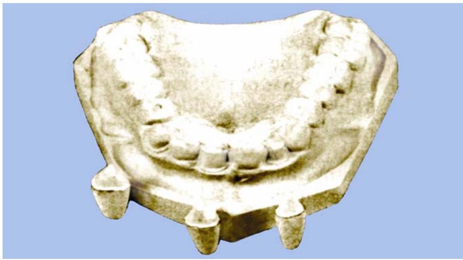
1.26.1. Solid Working Cast With Augmenting Individual Dies (Figure 1.18)
1.26.1.1. Some dentists prefer to use a solid working cast (noremovable dies) to develop the occlusal surfaces and the proximal, buccal, and lingual contours of wax patterns. The patterns are then transferred to individual dies for completion of the margins. A working cast with augmenting individual dies can be made by pouring a rubber base impression twice; first, to pour the dies of the individual abutments, and second, to pour the cast. Do not use reversible hydrocolloid impressions because the material is susceptible to change.
1.26.1.2. Before pouring the dies, “box” the imprint of each abutment with matrix band strips to confine the die material. An alternative is to pour a sectional or partial cast that includes several dies and saw the dies apart later. Add enough die material to form an extension that is adequate for easy handling of the die. Allow this first pour to set for 45 minutes.
1.26.1.3. Remove the first pour from the impression and set it aside where it will not be damaged. Before repouring the impression, wax a ring of boxing wax around the top of each abutment margin. This ring will expose the margin so the wax pattern can be made and the casting can be seated on the cast. Immediately repour the impression to construct a complete, solid working cast.
1.26.1.4. After removing the working cast from the impression, trim it on a cast trimmer and let the cast dry. Use this cast to establish the occlusal form, proximal contacts, and occlusal two-thirds of the axial contours of the wax patterns. Use the trimmed individual dies to complete the final adaptation of the wax pattern margins.
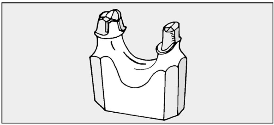
1.26.1.5. Using this technique, make a single-piece die for FPDs (Figure 1.19)
Leave the die for each abutment joined to the other by a common base. Because the dies are never separated from each other, greater accuracy can be expected. Pour the involved part of the arch and die stone for an adequate base. When trimming the one-piece die, be sure to cut back the edentulous ridge area, allowing good access for contouring the interproximals and for finishing the margins.
Figure 1.18. Solid Working Cast With Augmenting Individual Dies.
natural_image
Ancient ceramic mask with multiple teeth and a central cavity, displayed against a plain blue background (no text or symbols visible)
Figure 1.19. One-Piece Die for an FPD.
natural_image
Technical line drawing of a U-shaped mechanical component with two protruding pins (no text or symbols)
1.26.2. Solid Working Cast With Dowel Pinned Cast. The extreme stability of polyvinylsiloxane impression material allows the production of multiple and nearly identical casts from one impression. For fixed prosthodontics, it is most useful to have one pinned and sectioned cast (paragraph 1.19) and one “solid” cast. These two casts allow the production of an extremely accurate prostheses.
¶ Section 1G — Cast-Mounting Procedures
¶ 1.27. Overview
The most convenient time to unseat a removable die for the first time is before mounting the working cast. You have maximum access to the tips of the die extensions. However, the best time to mount a cast is before the first release of removable dies from their seats. A working cast has a better chance of fitting against an opposing cast or into a jaw relationship record with the greatest possible accuracy. The accuracy of the mounting is the primary consideration. The problem then becomes one of providing access to the tips of die extensions in the working cast's mounting.
¶ 1.28. Die Extension Access
1.28.1. Cover the tips of the extensions with any type of tape that sticks to damp surfaces (Figure 1.17-I)
1.28.2. Place a moundof clay on top of the tape and shape it so the stone used in mounting the cast will not block direct access to the extension tips (Figure 1.17-J)
1.28.3. Mount the maxillary cast with facebow (Figures 1.17-K and -L)
1.28.4. Mount the mandibular cast (Figure 1.17-M)
1.28.5. Peel out the clay and tape after the stone sets (Figure 1.17-M)
1.28.6. Pop loose the dies and all other removable areas of the cast (Figure 1.17-N)
¶ 1.29. Mounting the Maxillary Cast
1.29.1. Average Method. See Volume 1, paragraph 6.12.
1.29.2. Facebow Transfer. An occlusion rim is part of the facebow transfer apparatus for an edentulous or nearly edentulous maxillary arch. In fixed prosthodontic cases, a significant number of maxillary teeth are usually present and an occlusion rim is not often used. Instead, the dentist will cover the facebow's bite fork with a uniform thickness of base plate wax or modeling compound. The dentist will warm the material and impresses it against the maxillary teeth, picking up a series of incisal edge and occlusal surface indentations. After the facebow transfer has been sent to the laboratory, set the maxillary cast in the indentations when the facebow is being related to the articulator as follows:
1.29.2.1. Hanau H2 Articulator. See the description in Volume 1, paragraph 7.47.2) The only difference in the description is that the occlusal plane formed by stone teeth (instead of the plane of an occlusion rim) is oriented parallel to the base of the articulator.
1.29.2.2. Whip-Mix Articulator.
1.29.2.2.1. Prepare the Articulator for the Cast-Mounting Procedure.
1.29.2.2.1.1. The lower frame of the articulator has the letters L (large), M (medium), and S (small) engraved on each of its corners on the back side. Screw the two condylar elements into the setting that corresponds with the patient's condylar width of L, M, or S as recorded on the front of the facebow by the dentist.
1.29.2.2.1.2. Tighten the condylar elements firmly in place with the box wrench. Then set the upper frame of the articulator to the same width of L, M, or S by removing or adding the correct number of spacers on the shafts of the condylar guides.
1.29.2.2.1.3. Use two spacers on each shaft for L, one on each shaft for M, and none for S. Make sure the shafts are replaced so these spacers are in tight contact on both sides between the articulator frame and the condylar guides. When spaces are using spacers, always place those with the beveled sections closest to the condylar guides, with the bevels next to the guides. Also be sure the horizontal line on each spacer aligns with the one on the back of the condylar guide.
1.29.2.2.1.4. Spacers are not interch angeable between articulators. When spacers are not in use, place them on the incisal guide pin so they stay with the same instrument. Set the condylar guides at a 30-degree angulation in preparation for attaching the facebowassembly. The side shift guide settings are irrelevant at this time. Firmly secure clean mounting plates on both the upper and lower frames of the articulator. Be sure the adjustable incisal guide table is in place on the lower frame and remove the incisal guide pin.
1.29.2.2.2. Secure the Facebow to the Upper Frame.
1.29.2.2.2.1. The Whip-Mix faceb ow is most convenien tly used with a Whip-Mix articulator. The facebo w is de signed soneither side arm can be moved laterally without the other arm moving a corresponding distance. The facebow is attached to the upper frame of the articulator by placing the holes in the medial side of the plastic ear pieces over the pins provided on the outside flange of the condylar guides.
1.29.2.2.2.2. Remove the plastic nasion relator and its bracket from the crossbar of the facebow and loosen the three thumb screws slightly. To secure the facebow in place, hold it in one hand and with the other and lift off the upper member of the articulator.
1.29.2.2.2.3. While holding one arm of the facebow against your body, guide first one pin and then the other onto the outer flanges of the condylar guides and into the holes on the medial side of the plastic ear pieces. Allow the anterior end of the u pper frame of the articulator torest on the crossbar of the facebow and then tighten the three thumb screws while still pressing the facebow arms firmly against your body.
1.29.2.2.2.4. Replace the upper frame with attached facebow onto the lower frame, allowing the fork toggle of the facebow torest on the incisal guide table.
1.29.2.2.3. Mount the Maxillary Cast.
1.29.2.2.3.1. Seat the cast in the facebow fork registration. Then lift the upper arm of the articulator and apply a moundof well-mixed stone to the base of the cast. Using one hand for support to prevent any movement of the facebow fork or cast, close the upper arm of the articulator until it againtouches the cr ossbar of the facebow, sinking the mounting plate into the soft mounting stone. Hold the cast in position until the mounting stone has set and then remove the facebow from the articulator.
1.29.2.2.3.2. When a facebow transfer is made to a Whip-Mix articulator, expect the occlusal plane to have an anterior tilt with reference to the horizontal plane of the articulator. If the occlusal plane and the articulator's horizontal plane happen to coincide, it is pure chance.
¶ 1.30. Mounting the Mandibular Cast
1.30.1. Mounting at the Patient's Actual or Estimated Occlusal Vertical Dimension. This is characteristic of two kinds of cast relating methods, dentulous casts fitted together in MI and occlusion rim -jaw relationship records. Follow the pin-f lush ru le b elow with this kindof mounting:
1.30.1.1. Mount the upper cast by the average or the facebow transfer method. Mount the upper cast while the incisal guide pin is flush with the upper member of the articulator. In the Whip-Mix facebow transfer procedure, remove the pin before placing the facebow on the articulator. After facebow mounting of the maxillary cast is finished, replace the incisal guide pin (pin - flush).
1.30.1.2. Lock the condylar elements down in the most retruded position. The Hanau articulator has centric locks to accomplish this. On the Whip-Mix articulator, set the side shift guide on each side in an extreme negative position and outward as far as possible. While this will lock the condyles in a retruded position, be careful not to force the articulator into an over opened position because the instrument could be seriously damaged.
1.30.1.3. Invert the articulator.
1.30.1.4. Place opposing dentulous casts in the best MI possible or position casts in an occlusion rim record, if provided.
1.30.1.5. Stabilize the assembly with wires and modeling plastic.
1.30.1.6. Apply a moundof stone to the base of the lower cast and close the articulator into it. The condyle elements should be in their most retruded positions in the condyle guides.
1.30.2. Mounting at a Vertical Dimension Other Than the Patient's Actual or Estimated Occlusal Vertical Dimension.
1.30.2.1. This condition is characteristic of mountings made withinterocclusal jaw relationship records. An interocclusal record is one that has been made between the teeth of opposing arches. Interocclusal records are made in different ways. Some are made from wax wafers, others are made from zinc oxide and eugenol paste carried into the mouth on a perforated metal plate, and still others are made with zinc oxide and eugenol paste supported by gauze held in a frame.
1.30.2.2. The one thing all interocclusal records have in common is thickness. Because they have thickness, they usually hold opposing teeth apart at a vertical dimension that is open from the patient's occlusal vertical dimension. It is common practice to compensate for the thickness of an interocclusal record before the lower cast is attached to its mounting ring.
1.30.2.3. Mount the maxillary cast with a facebow transfer supplied by the dentist. The thicker the interocclusal record, the greater the need for a facebow transfer. Opposing casts mounted at an open vertical dimension without benefit of a facebow transfer will be inaccurately related when the articulator is subsequently closed to the patient's actual or estimated occlusal vertical dimension.
1.30.2.4. Make an estimate of how thick the record is. Using the pin-flush position as the starting point, open the vertical dimension accordingly. The range of compensation varies from about 1 mm for a gauze-supported record to 5 mm for a record made with wax or with metal plates.
1.30.2.5. Invert the articulator and position the interocclusal record on the teeth of the maxillary cast. Place the teeth of the mandibular cast in their corresponding indentations. Stabilize the assembly with wires and modeling plastic. A good interocclusal record will show the indentations of incisal edges and the cusp tips of posterior teeth, but no more. Records showing more than the requirements have to be trimmed with the sharpest knife possible until only incisal edges and cusp tips are visible. It is unacceptable practice to force a cast into a record that laps onto the facial or lingual surfaces of teeth. There is a strong possibility the record will warp. There is no way of determining whether the cast is fully seated in the record.
1.30.2.6. Mount the mandibular cast. After it has been mounted, remove the interocclusal record. Decrease the vertical dimension to the patient's actual or estimated occlusal vertical dimension. Make a note of the final pin setting on the upper cast's stone mounting.
¶ 1.31. Semiadjustable Articulator Settings (Hanau H2 and Whip-Mix)
1.31.1. Average Method.
1.31.1.1. Note that the occlusal plane is parallel to the horizontal plane of the articulator.
1.31.1.2. Remember, the scale should read “+30 °.” If, for some reason, the occlusal plane has not been mounted parallel to the horizontal plane of the articulator, set the horizontal condylar guidance other than +30 ° to compensate for the amount of deviation (Volume 1, Chapter 6). For example, many dentists like to use a facebow transfer with average settings on a Whip-Mix articulator. The occlusal plane will rarely come out parallel to the articulator’s horizontal plane after a Whip-Mix facebow transfer. Expect a positive deviation of about 10 to 15 degrees. In order for the horizontal condylar guide (slope of the patient’s articular eminence) and the occlusal plane to intersect at the statistical average of +30°, set the horizontal guidance at the +40° to +45° mark on the scale.
1.31.1.3. Note that lateral condylar guidance equals 15 degrees.
1.31.1.4. Set the incisal guide table initially at 0 °. Make adjustments to the table after determining the occlusion scheme for the prosthesis.
1.31.1.5. On a Whip-Mix articulator, use the “medium” intercondylar distance setting. (For a Whip-Mix articulator with immediate sideshift guides, use the 0.5 mm setting.)
1.31.2. Semiadjustable Method.
1.31.2.1. Hanau H2 Articulator.
1.31.2.1.1. Mount the maxillary cast with a facebow transfer.
1.31.2.1.2. Use a protrusive jaw relationship record to set the horizontal condylar guidance. First, mount the maxillary and mandibular casts in the centric position (centric relation, MI) the dentist wants. Then, loosen the horizontal condylar guidance lockscrews. The guidances should rotate freely within their housings. Also loosen the centric locks to permit movement of the condyle elements within their guides.
1.31.2.1.3. Fit the supplemental protrusive jaw relationship record provided by the dentist onto the teeth of the mandibular cast and fit the maxillary teeth into their corresponding indentations. Rotate the horizontal guidances back and forth within their housings until settings are found where the maxillary cast seats solidly on all indentations in the record. Tighten the guidance lockscrews and remove the protrusive record.
1.31.2.1.4. Use the following lateral condylar guidance formula. L = H/8 + 12. See Volume 1, Chapter 6, for an explanation.
1.31.2.1.5. Set the incisal guide table at 0° until plans for the fixed prosthesis occlusion are made.
1.31.2.2. Whip-Mix Articulator (Figure 1.20)
1.31.2.2.1. Use the facebow transfer to set the intercondylar distance and to mount the maxillary cast.
1.31.2.2.2. To set horizontal and lateral condylar guidances, use a set of right and left lateral excursion interocclusal records. First, mount the maxillary and mandibular casts in the centric position ordered by the dentist (centric relation, MI).
1.31.2.2.3. After removing the registration record, set both condylar guides at zero inclination and the side shift controls at their most open position (45 °) (Figure 1.20-A). Raise the incisal guide pinto prevent interference. With the upper frame and its cast inverted, carefully seat the left lateral excursion interocclusal record on the upper cast. Holding the upper frame in one hand and the lower frame in the other, place the left condylar element in the left condylar guide. Gently seat the lower cast into the indents of the lateral record and lightly hold the articulator and casts in position with one hand.
1.31.2.2.4. Notice in Figure 1.20-B that the right condylar element has moved away from both the superior and posterior surfaces of the condylar guide and, in most cases, toward the median line. To set the inclination of this right guide, loosen its holding screw and rotate the guide toward the condylar element until contact is established. It is advisable that contact be judged by sight, rather than by depending on the sense of touch (Figure 1.20-C). This helps to ensure that the casts are not forced out of position from the interocclusal record. Tighten the locking screw to fix the guide in this position.
1.31.2.2.5. The next step is to get the correct amount side shift by loosening the side shift guide locking screw and then moving the guide into contact with the condylar element (Figure 1.20-D). Retighten the locking screw. After the right horizontal and lateral condylar guidances have been set, adjust the left side of the articulator with the right lateral excursion record.
Figure 1.20. Adjusting Horizontal and Lateral Condylar Guidance (Whip-Mix Articulator).
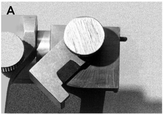
natural_image
Close-up of metallic mechanical components including a circular component and a square bracket, with no visible text or symbols.
Set side shift controls
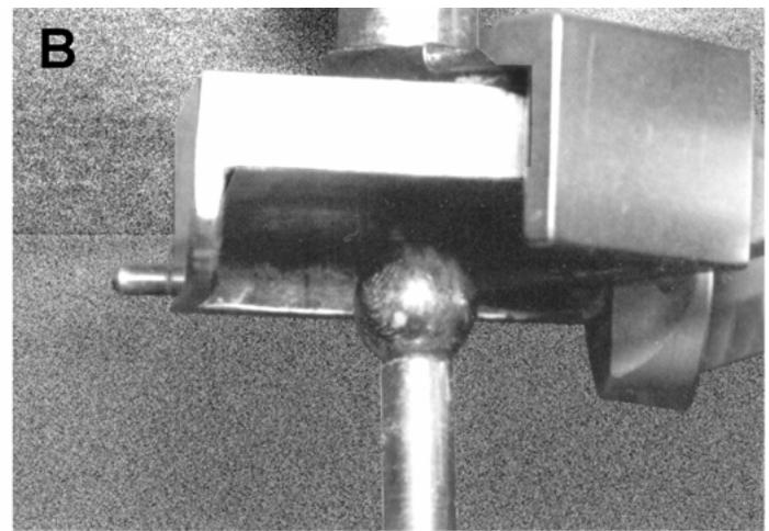
natural_image
Close-up of a metallic mechanical component with a cylindrical shaft and mounting bracket (no visible text or symbols)
Position left interoccusal record and view condyle/guide relationship
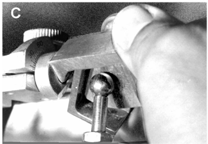
natural_image
Close-up of a mechanical clamping device with metal components and a hexagonal bolt, no visible text or symbols
Adjust guide to contact condyle
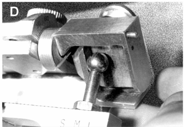
natural_image
Close-up of a mechanical clamp or clamping device with metal components and a small metallic rod inserted (no visible text or symbols)
Adjust Bennet plate to contact condyle
1.31.2.2.6. Some Whip-Mix articulators are purchased with an immediate side shift guide option. The option consists of four sets of guides that permit from 0.25 to 1 mm of immediate side shift, depending on the set chosen. The rule for selecting a set is in Volume 1, Chapter 6. Substitute the chosen set for the set already on the articulator.
1.31.2.2.7. Remember, the incisal guide table is initially set at 0°. Make adjustments to the table after determining the occlusion scheme for the prosthesis.
¶ 1.32. Microscope Utilization
1.32.1. The use of a microscope can greatly enhance the quality of fixed prosthodontics. Many procedures during the fabrication process benefit from magnification to achieve a quality product.
1.32.2. Microscopes are available with a swivel -type attachment to the bench or a bench top model. The swivel arm allows the technician to ergonomically work directly under the microscope. It also allows several workstations access to a single instrument, thereby reducing equipment costs. The bench top model does not allow the technician to ergonomically work at the laboratory workstation and shouldonly be used for interim periods.
1.32.3. Generally, the power of magnification for laboratory use is in the range of 10x to 30x. Microscopes may be used anytime detailed intricate work is being performed. Their most common uses are for die trimming and marking the margins on fixed restorations, achieving adaptation of wax to the margin areas of fixed restorations, s eating fixed restorations on the die after casting, and quality control assessment of completed restorations. All of these procedures are shown in this chapter.
¶ 1.33. Die and Working Cast Preparation Before Waxing
(NOTE: The assumptions are that the working cast is mounted against its opponent in an articulator and the removable dies are removed from the cast and ready for trimming.)
1.33.1. Trimming the Die. The combination of cuts a dentist makes on an atural tooth for purposes of receiving a restoration is called a preparation. The most peripheral extent (outline form) of a preparation is the margin. A fixed prosthetic restoration, such as an onlay or a crown, has to cover the entire tooth surface a dentist has cut or prepared. The margin of the preparation alsorepresents the border or margin of a proposed restoration. Depending on the kindof preparation the dentist has made, part or the entire margin will be low gingival tissue. Before a die can be used to make a restoration, any dental stone that covers the margin of a preparation has to be trimmed away. NOTE: Although die trimming is the dentist's responsibility, a technician is occasionally called onto do it under the dentist's supervision. If a technician is to trim dies, make wax patterns, and finish castings competently, he or she must have knowledge of basic preparation forms and margin styles (Figure 1.21).
1.33.1.1. Margin Styles (Figure 1.22)
1.33.1.1.1. Shoulder. A shoulder margin is one that intersects with the surface of a toothat a 90-degree angle. The junction of a restoration with a preparation at a shoulder is called a butt joint. This kindof margin is almost exclusively reserved for all-ceramic crowns or metal-ceramic restorations with facial porcelain margins because of porcelain's limitations as a restorative material. When fabricating an all-ceramic crown, the 90-degree angle between the margin and facial surface must be roundedor radial to prevent porcelain from fracturing. A thin, sharp margin would contribute toward better sealing a restoration to a tooth, but the physical properties of porcelain do not permit it to be used in that way.
1.33.1.1.2. Chamfer. The chamfer is usually the margin of choice for complete and partial metal crowns and pinledges.
1.33.1.1.3. Knife Edge. In most cases, the kn ife edge (or chisel edge) is considered an adequate substitute for the chamfer margin.
Figure 1.21. Preparation Forms.
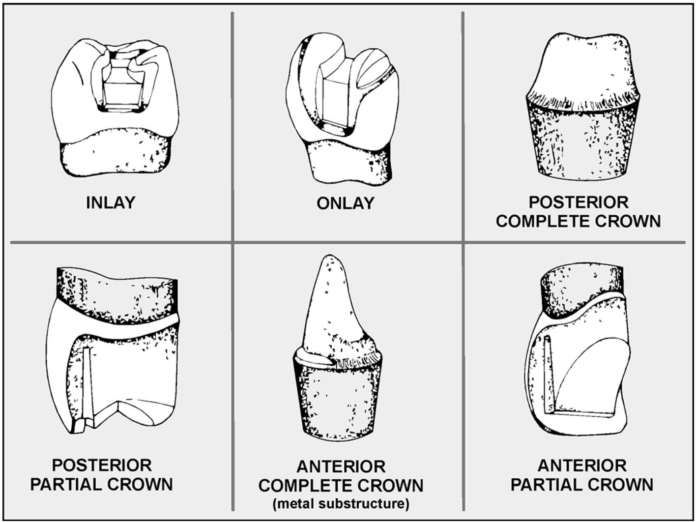
text_image
INLAY
ONLAY
POSTERIOR COMPLETE CROWN
POSTERIOR
PARTIAL CROWN
ANTERIOR COMPLETE CROWN
(metal substructure)
ANTERIOR
PARTIAL CROWN
Figure 1.22. Margin Styles.
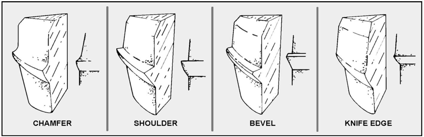
text_image
CHAMFER
SHOULDER
BEVEL
KNIFE EDGE
1.33.1.1.4. Bevel. There are many areas in the various preparations for reception of a metal casting where shoulder-like cuts are made. Examples include the gingival seat of an inlay or onlay and the faciogin gival area of a complete anterior crown. The place where a
conventional shoulder would join with the surface of a toothat 90 degrees is changed into a 45-degree angle. This alteration, called a bevel, has the desirable effect of lengthening and sharpening a restoration's margin.
1.33.1.2. Die Trimming. Define margins and reshape the area immediately below the margins before making wax patterns. Use a microscope to perform these steps to be able to clearly see the margin. When refining the wax margins of a pattern, rest the instrument on the die base. Figure 1.23 shows how a deeply ditched die can influence overcontouring of the pattern. The margin definition can be performed in two steps: (1) remove excess stone next to the gingival margin of the preparation, and (2) define the gingival margin by careful carving.
Figure 1.23. Pattern Contour Influenced by Die Trimming.
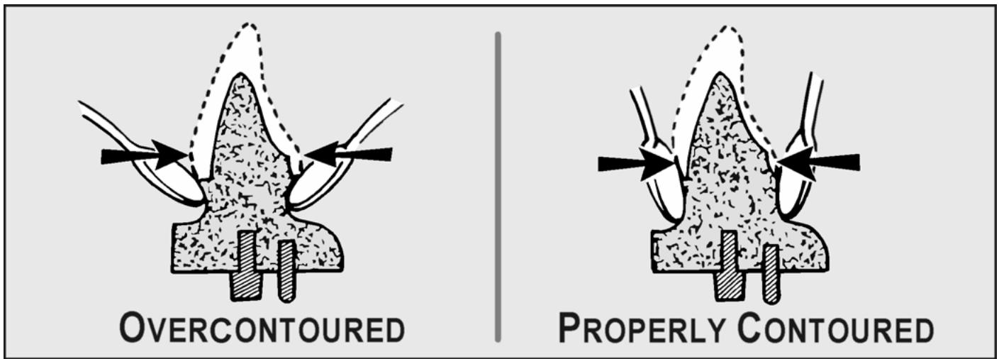
text_image
OVERCONTOURED
PROPERLY CONTOURED
1.33.1.2.1. Bulk Trimming. Do the initia 1 bulk trimmings with a pea r-shaped bur (Figure 1.24). Expose about 4 mm of stone below the margin without creating a deep recess. The die contours should resemble the root portion of a natural tooth.
Figure 1.24. Bulk-Trimming and Refining a Die Margin.
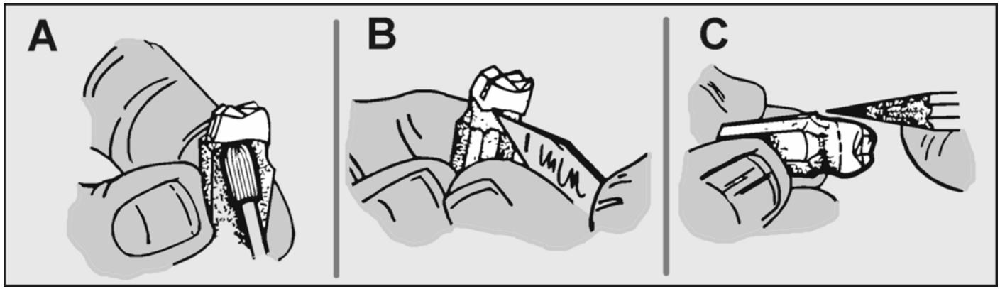
natural_image
Three-panel illustration showing a hand using a tool, labeled A, B, and C (no text or symbols present)
1.33.1.2.2. Define the Margin. Do the final trimming with a #25 Bard Parker blade or beaver blade. At the mesial and distal surfaces, make the cuts straight down because the proximal contours of patterns are fairly straight. On the facial and lingual areas, strive for about 0.5 mm of undercut. Define only the gingival margins, not those prepared as supragingival (above the gingival crevice, as in a 3/4-crown preparation).
1.33.2. Preparing the Die.
1.33.2.1. Mark the Margins. To ensure the margins are highly visible, lightly outline them with a red wax pencil. Do not use a lead pencil because lead transferred to the investment mold can create pits in the casting. Then apply a very thin surface hardener over the marked margins. This prevents the red pencil line from smudging and maintains marginal integrity during the fabrication process.
1.33.2.2. Paint On the Die Spacer. Note that cement used during insertionexerts pressure (hydraulic effect) on a precision casting, which may prevent complete seating. The die spacer allows enough room for the film thickness of cement so the casting will seat completely. The covering must stop about 1 mm from the margin of the preparation. Properly applied, the material will measure between 20 to 40 microns thick.
1.33.2.3. Edentulous Ridge Modifications. These instructions apply to FPD cases. A dentist has to request the modifications. Pontics are supposed to be in positive contact with an edentulous ridge or constructed at an elevated level, totally out of contact. At times, contact is difficult to maintain. Sometimes, a pontic raises up slightly as a result of a soldering procedure. Occasionally, contact is finished and polished away. When pontic contact with the edentulous ridge is the goal, smooth off edentulous area irregularities just enough to permit correspondingly smooth contouring of the gingival surface of the pontic. Next, use a pencil to carbonize only the tissue contact areas and then carefully shave away the carbon. Shaving away two or three such carbon applications should give sufficient contact of the finished prosthesis with the edentulous ridge.
¶ Section 1H — Esthetics
¶ 1.34. Overview
In most cases, try to duplicate the patient's original teeth in color, form, and texture. (It is indeed especially helpful when the dentist sends a diagnostic cast of the patient's original dentition or the provisional prosthesis.) If a diagnostic cast is not available, rely on personal knowledge and experience. Sometimes, certain subtle changes or even a major change is indicated to preserve the smile and personality of the patient.
¶ 1.35. Morphology of Anterior Teeth
A thorough understanding of tooth morphology is essential to meet the esthetic demands of the patient. The eye is extremely sensitive to the outline form of objects, even more so when teeth are being viewed prominently silhouetted against the dark oral cavity. In fact, small differences in color will go unnoticed if the form and texture of the teeth are correct. Some technicians unknowingly create the same morphological features in every restoration they make. This approach lacks the personalization needed so the restoration will harmonize with the patient's physical characteristics. For a detailed discussion of tooth morphology, review Volume 1, Chapter 4. Discussion of morphology in this chapter will be limited to anterior teeth only.
1.35.1. Diagnostic Aids.
1.35.1.1. The exact size and form of the original tooth is usually produced in the restoration. However, because the technician is normally not directly involved with the patient and must rely only on the information present, this task can be very difficult. Examples of diagnostic aids that should be available include preoperative casts and casts made from impressions of diagnostic wax-ups or provisional restorations.
1.35.1.2. If a corresponding natural toothxists in the opposite side (contralateral tooth), its form may be duplicated in the final restoration. Also, the patient's remaining natural anterior and posterior teeth show characteristic ristics commonto all the teeth, but there are many instances where no diagnostic aids are available. Therefore, it may be desirable to save discarded maxillary and mandibular casts displaying different morphological features. These casts can be used as references when simulating the morphology of natural teeth in fixed prosthodontics.
1.35.2. Outline Form. The space available for crowns and FPDs will determine the dimensions of the restoration. A general guide, similar to that used for rem ovable prosthodontics (Volume 1, Chapter 7), can be used to determine the sizes of anterior teeth. According to this guide the central incisor is one-sixteenth of the length and width in relation to the length and width of the patient's face. Also, the basic form s of teeth (square, sq uare tapering, tapering, andovoid) should agree with the face form.
1.35.3. Sex. The idea that a person's sex determines the surface form of his or her teeth is invalid. Dental morphology seems to depend more on the patient's face form and personality than on his or her sex. The traditional feminine and masculine forms are now thought of a s displaying youthfulness or advancing age (wear).
1.35.4. Age. The changes that occur with aging can be attributed to attrition, abrasion, and/or soft tissue recession, as follows:
1.35.4.1. Attrition (Abrasion)
1.35.4.1.1. Attrition is most noticeable in the maxillary arch, but it alsoreveals some interesting details about the mandibular arch. The lack of wear due to youthis shown by the full length of the clinical crown in Figure 1. 25. Alsonote the effect attrition has on the incisal embrasures. At middle age, the incisal edges of the centrals are worn, but the laterals show only minimal wear. In later years, the lateral incisors beginto wear, resulting in a straight line extending from lateral to lateral.
Figure 1.25. Attrition of Maxillary Incisors With Aging.
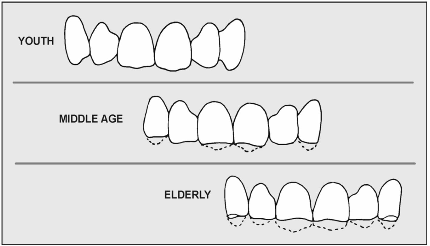
text_image
YOUTH
MIDDLE AGE
ELDERLY
1.35.4.1.2. Attrition with aging has a dramatic effect on the patient's smile. In youth, more of incisal edge extends below the lip and results in a vigorous appearance. As the length of the incisal edge shortens, an older appearance results.
1.35.4.1.3. The wear patterns associated with attrition are affected by the position of the teeth, direction of mandibular movement, and condition of the antagonists. Once these factors have been analyzed, reproduce the restoration's proper wear pattern, assuming the case is well mounted on a programmed articulator. If attrition advances, the dentin is exposed and a roughened surface results. The exposed dentin is porous and quickly stains to an orange-brown color. Especially apparent in the mandibular teeth (Figure 1.26), this is helpful to simulate aging changes.
Figure 1.26. Exposed Dentin Caused by Attrition of Mandibular Incisors.
text_image
ATTRITION
1.35.4.2. Soft Tissue Recession. The architecture of a person's gingiva changes with age (Volume 1, Figure 7.91). The soft tissues supporting the teeth receded gradually with age as shown in Figure 1.27. As the narrower root portions of the teeth are exposed, the teeth beginto appear triangular. This effect is also partially due to attrition at the incisal edge.
1.35.5. Patient Profile. In considering the effect patient profile has, the gingivoincisal profile of teeth may bestraight, convex, or slightly concave (Figure 1.28). Most teethexhibit a “rounding in” of the labial surface form in the incisa 1 third. This reduces the forward light reflection and prevents the incisal edges from appearing grossly protruded. The mesiodistal profile may bestraight, convex, or concave, depending on the shape of the zygomatic arch.
1.35.6. Embrasures. All of the four embrasures (incisal, gingival, labial, and lingual) are important. The incisal embrasure is particularly important because it has the most effect on outline form. The location of the contact areas separates the embrasures from each other and helps shape the embrasure form. Generally, teeth with squ are outlines have contact areas longer than those with more taperedoutlines. When more separati on between teeth is desired, shorten the contact area to expose more space and tissue in the interproximal. The labial surface and embrasure form also has a significant effect on appearance. A convex labial surface with widened embrasure form will scatter reflected light rays and appear narrower than a flat bial surface with closed embrasure form.
Figure 1.27. Attrition and Soft Tissue Recession of Maxillary Teeth With Aging.
text_image
YOUTH
ELDERLY
Gradual Recession
of Cervical Tissues
Upper
Lip Line
Attrition of Incisal Edge
Figure 1.28. Effect of Patient Profile on the Surface Form of Teeth.
text_image
Mesiodistal
Profile
Gingivoincisal
Profile
1.35.7. Long Axis. Line angles, heights of contour, and the incisal edge determine the long axis. Restorations should appear as if they are actually growing in place. The long axes of restorations should be in line with the inclination of the root eminences. It is helpful to scribe lines on the cast to indicate this inclination. Withanteriors, the root generally inclines distal ly and, as a result, the apical crest is often formed in the distal thirdof the cervical portion. A restoration im properly contoured in the cervical area will not only look unnatural, but may also cause tissue inflammation. The long axis is generally at right angles to the incisal edge. When teeth lap over or under each other, their long axes change and the incisal edges must be made toreflect that change. When all of these factors have been met, harmony will be present.
1.35.8. Midline. The dental midline is best determined by the patient's facial midline. Many believe the midline of the restoration should match the opposing arch. The exact position of the midline relative to the opposing arch is not as important as the size and arrangement of teeth. At a glance, you remember the arrangement and size of teeth before noticing anything else.
1.35.9. Incisal One-Third. The incisal one-thirdof mandibular anteriors is often in the “esthetic zone.” The incisal edge is gradually lost with aging. Attrition occurs on the lingual surface of the maxillary incisors and the labia l surface of the mandibular incisors. As attrition proce eds, concavities on the lingual fossa be come more apparent. Give careful consideration to these areas when carving the lingual fossae and lingual embrasures.
1.35.10. Surface Characterization. If the surface characterization of restorations is not accurately simulated, reflection from the surface and luster will differ from those of the adjacent teeth, making the restoration appear artificial.
1.35.10.1. Ridges and Grooves. Anterior teeth usually have three labial ridges and two shallow labial grooves between them. In the cervical third, one to four horizontal grooves exist with horizontal ridges between them. There may also be many other irregularities, such as fine developmental lines, particularly in younger dentition (Figure 1.29). The older the person, the less characterization is present and the smoother the tooth surfaces are. If corresponding teeth on the opposite side are present, simply reproduce those surface characterizations in the restoration. However, if the contralateral forms are not available, the remaining dentition will show surface characteristics typical of that patient.
1.35.10.2. Surface Textures. The surface texture of a restoration should be slightly more emphasized than the adjacent teeth being matched. A textured surface will diffuse and scatter light in an irregular manner. Surface texturing may help to conceal slight differences in color and make the restoration appear more natural.
¶ 1.36. Improving Esthetics
1.36.1. Changes in Tooth Width.
1.36.1.1. Narrow Spaces. A narrow space can be treated by overlapping at the incisal edge (Figure 1.30-A). Another way to treat the same problem is to flatten the facial surface and move the contact facioincisally (Figure 1.30-B).
1.36.1.2. Wide Spaces. When the space to be filled is wider than normal, the problem is more difficult. Figure 1.31-A shows how to treat this wide space by rounding the labial surface and moving the contact gingivally. This moves the visible labial line angles to the center of the tooth, giving the illusion that the tooth is narrower than the space it occupies. Still another method would be torecontour the restoration in a lingual direction and move the contact areas lingually (Figure 1.31-B). (Movement of the contact areas labi ally has the opposite effect, which is to make the tooth appear wider.) Vertical lines on the labial surface will also make teeth appear narrower.
Figure 1.29. Surface Characterization of Maxillary Anterior Teeth.
text_image
CENTRAL LATERAL CUSPID
TRIANGLE
SQUARE
OVAL
IRREGULAR
Figure 1.30. Making Narrow Teeth Appear Wider.
Figure 1.31. Making Wide Teeth Appear Narrower.
1.36.2. Changes in Tooth Length.
1.36.2.1. Long Crown Length. Teeth that have become periodontally involved have extra long clinical crowns which can be made to appear shorter by creating a definite cervical line (Figure 1.32). Placement of the cervical line is determined by the adjacent natural teeth and overall appearance of crown length. The crown can be made to appear even shorter by adding gingival stain to the root portion. An alternative approach would be to reduce the cervical collar and add gingival shade porcelain to restore the contour. Gingival shade porcelain may be supplied by the manufacturer or made by combining various amounts of modifiers to dentin porcelain.
Figure 1.32. Cervical Collar and Shading To Reduce Length.
natural_image
Three smooth, rounded stones arranged horizontally on a light blue background (no text or symbols)
1.36.2.2. Short Crown Lengths. Short teeth can be made to seem longer by adding vertical lines or a vertical concavity to the surface texture. These procedures will give the illusion of length, but only to a limited degree. A greater increase in length can only be made by surgically repositioning the gingival margin.
1.36.3. Changes in Tooth Position. The effect of tooth position and alignment of a tooth within the arch may be more important than the actual form of the tooth itself. This can be demonstrated by using three sets of teeth of the same mold and shade. If each set were arranged into three different arch forms (square, tapering, andovoid), the teeth in the squarely aligned arch would appear square, those in the tapering form would appear tapered, and those in the ovoid arrangement would appear ovoid.
1.36.4. Tooth Rotation. Rotating a tooth about its axis to create an overlay allows the placement of a wider tooth mesiodistally into a smaller space. Subtle axial rotation (Figure 1.33) gives a natural appearance to the arrangement of teeth, but taking it to the extreme will have an opposite effect and may not be pleasing as thetically. A tooth may lose some of itsidentity, depending on the degree of rotation. Figure 1.34 shows how dramatic this change might be if the distals of the six anterior teeth are rotated in and the mesials out. Notice how much narrower the teeth appear even though they occupy the same relative positions.
¶ Section 1I — Waxing Individual Cast Restorations and FPD Retainers
¶ 1.37. Overview
The procedures described in this section deal with choosing a scheme of occlusion and waxing a pattern.
Figure 1.33. Effect of Subtle Axial Rotation on Appearance.
Figure 1.34. Effect of Rotation on Apparent Width.
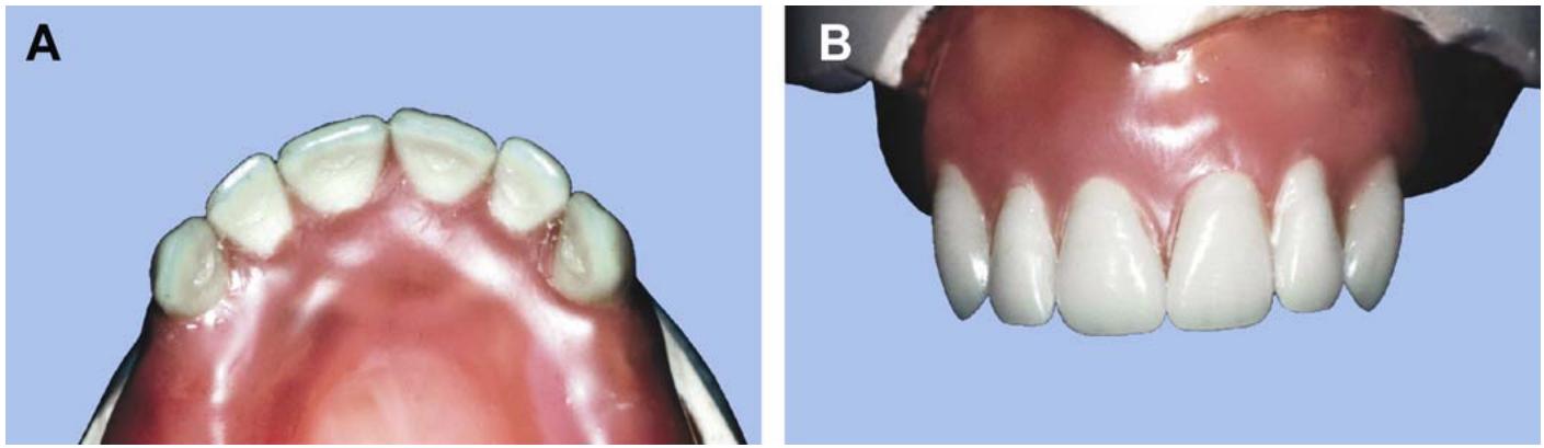
¶ 1.38. Determining the Occlusion Scheme for the Fixed Prosthesis and Setting the Incisal Guide Table
1.38.1. The first stepin selecting an occlusion scheme for a fixed prosthesis is to analyze what kindof occlusion the patient has. Once this has been decided, the dentist has the option of imitating it or changing it when ordering the restoration. The technician must have enough basic knowledge to understand and follow the dentist's directions.
1.38.2. There are complex cases where there is no definite way of telling what kindof occlusion the patient originally had. In these cases, the dentist is forced to choose a scheme of occlusion based oneducated guess rather thandrawing conclusions from directly observable tooth relationships. The standards for recognizing natural tooth occlusions are in Volume 1, Chapter 5.
1.38.3. In fixed prosthetic dentistry, an incisal guide table is used to protect the dental stone teeth against abrasion, to program the movement of an articulator so a restoration can be made that conforms to the movement, or for both reasons. Decide on MI and eccentric occlusion patterns as follows.
1.38.3.1. Maximum Intercuspation (MI)
If a patient has a cusp-to-embrasure type of MI and there is an opportunity to switch the prosthesis over to the cusp-to-fossa variety, do so.
1.38.3.2. Eccentric Occlusion (Example #1)
In this example, a posterior fixed prosthesis has to be made and the guiding surfaces of anterior teeth in eccentric movements are intact.
1.38.3.2.1. Select an Occlusion. Barring unusual circumstances, the rule is to make a posterior fixed prosthesis blend into the existing occlusion. For example, after the prosthesis is finished, a cast that showed anterior guidance should show posterior tooth relationships characteristic of anterior guidance.
1.38.3.2.2. Set the Incisal Guide Table (Figure 1.35)
When casts move by one another in lateral and protrusive excursions, the surfaces of stone teeth wear away rapidly. When the objective is simply to preserve whatever tooth guidance there is between opposing arches, adjust the incisal guide table to minimize the wear on stone surfaces. Place the maxillary and mandibular casts in protrusion and tilt the incisal guide table until it is a hair's breadth short of contact with the pin. Place the casts in right and left lateral excursion relationships and adjust the wings of the incisal guide table in the same way.
Figure 1.35. Setting the Incisal Guide Table.
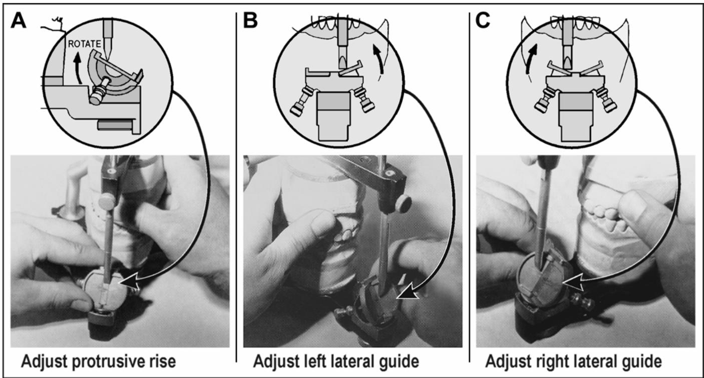
1.38.3.3. Eccentric Occlusion (Example #2)
In this example, an anterior fixed prosthesis has to be made and the key eccentric movement guiding surfaces of anterior teeth are in volled in the restoration (lingual surface of a maxillary canine, facial surface of a mandibular canine).
1.38.3.3.1. Select an Occlusion. The dentist will decide whether the case is going to be rebuilt in anterior guidance or in group function.
1.38.3.3.2. Set the Incisal Guide Table. The objective is to make the articulator move laterally as if the guiding surfaces of anterior teeth had already been restored to the type of occlusion the dentist wants. First, slant the incisal guide table to match the patient's actual or programmed rise from MI to anterior tooth contact in protrusion. Next, set the lateral wings to make the case behave like the type of occlusion chosen for the affected side or sides.
1.38.3.3.3. Build the Anterior Fixed Prosthesis. Do this to correspond to the movements programmed into the articulator.
1.38.3.4. Eccentric Occlusion (Example #3)
In this example, a mixture of anterior and posterior fixed units have to be made in the same arch, and key eccentric movement guiding
surfaces of anterior teeth must be restored. Directions for selecting an occlusion and setting the incisal guide table are essentially the same as those given in Example #2 (paragraph 1.38.3.3). The anterior restorations are waxed first, and then the posterior units are waxed to conform to the type of occlusion chosen.
1.38.4. Custom Incisal Guide Tables.
1.38.4.1. An adjustable incisal guide table looks like a precision adjustment mechanism; but, in reality, it is rather crude. There is a relatively common type of lateral movement where a combination of group function and anterior guidance occurs. As a lateral movement out of MI begins, the posterior teeth on the working side are in group function. As the lateral movement progresses, the anterior teeth on the working side make sufficient contact to separate the posteriors (Volume 1, Chapter 5).
1.38.4.2. In other kinds of cases, the teeth of patients with marked Class II jaw relationships may follow irregular protrusive paths. An adjustable incisal guide table cannot be set to produce these kinds ofarticulator movements. To deal with the problem, some dentists use a custom incisal guide table made from self-curing plastic. Those who use this type of table usually make it before sending the case to the laboratory.
1.38.4.3. To make a custom incisal guide table.
1.38.4.3.1. Set the tilt of an adjustable table and its wings at 0°. Lubricate the top of the table with a thin layer of petrolatum.
1.38.4.3.2. Ensure the rounded end of an incisal guide pin rests on the table.
1.38.4.3.3. Remember, an incisal guide table is used to protect dental stone teeth against abrasion and to program the movement of an articulator so a restoration can be made that conforms to the movement. When the latter reason is the justification formaking a custom table, wax up the key restorations that take part in the lateral and protrusive guidances first.
1.38.4.3.4. Add a layer of self-curing resinto the top of the adjust table table and crudely form the desired guidance paths in the resin as it cures.
1.38.4.3.5. Carve any final refinements into the cured resin with a bur or other grinding instrument.
¶ 1.39. Instruments
There are many kinds of instruments for applying wax to dies and shaping patterns, but the following are typical: (NOTE: If the wax additive [ positive waxing, functional waxing] technique is used, a set of Peter K. Thomas's waxing instruments is desirable.)
1.39.1. Beale #7 (spatula, dental wax)
1.39.2. Roach carver (dental carver, wax)
1.39.3. Hollenback #1 (dental carver, amalgam, and wax)
1.39.4. Woodson #1 (plugger, plastic filling, dental)
1.39.5. Electric waxing unit (therm – ostatically controlled)
Many of the same instrument mentioned in paragraphs 1.39.1 through 1.39.4 are available with the electric waxing unit. This tool’s advantage is that the temperature for applying wax can be precisely controlled.
1.39.6. Electric wax heater (thermostatically controlled)
This heater keeps wax in a molten state at a constant temperature without burning it.
1.39.7. Artist brushes, one stiff and one soft. The stiff brush is used to smooth irregularities on wax occlusal surfaces; the soft brush is used to dust zinc stearate disclosing powder onto a pattern's occlusal surface for checking its occlusion with opposing teeth.
¶ 1.40. Materials
Materials for applying wax to dies and shaping patterns include die lubricant and types A and C inlay wax (the best available).
¶ 1.41. Steps in Waxing a Pattern
1.41.1. Wax expands when heated and contracts when cooled (about 0.02 percent for each degree Fahrenheit of temperature change)
Assume that a pattern, waxed under a light bulb near a Bunsen flame, is invested in another part of the room where the temperature might be 10 to 15°F cooler. Expect the pattern to shrink. During the subsequent casting procedure, gold contracts about 1.25 to 1.5 percent from the molten to the solid state. Expansion of the investment mold is supposed to compensate for the predictable contractions of solidifying gold and not for unanticipated wax pattern shrinkage.
1.41.2. To obtain a satisfactory fit of a casting to a die, you have to be aware of environmental factors that might affect the stability of inlay wax. Try to wax and invest wax patterns in an area of the room where the temperature is relatively constant. Use room temperature water for the investment mix and invest the pattern as quickly as possible after completion.
1.41.3. Lubricate the die, proximal surfaces of adjacent teeth, and occlusal surfaces of opposing teeth.
1.41.4. Cover the die with a primary layer of wax (wax blank) as a foundation for the rest of the pattern. One method that is adaptable to any type of preparation is to apply molten wax with a #7 wax spatula, completely covering the preparation's surfaces before any part of the wax cools. Once you have laid down a full layer of coverage, you can proceed to build the rest of the pattern at a more leisurely rate.
1.41.5. Another method that is particularly useful when waxing complete crowns is to dip the lubricated die into a pool of molten wax. An electric wax heater is perfect for the job. Use second dip for heavier initial coverage. On e of the major objectives in this step is to begin forming an accurately fitting pattern with smooth internal walls. Avoid grossly overextending the wax blank. Carefully remove excess wax from all margins.
1.41.6. Flow on additional wax with a spatula and contour the pattern. The techniques for occlusal and axial contouring of wax patterns are:
1.41.6.1. Negative waxing, which is the buildup, smash, and carve technique (Figure 1.36), as follows.
1.41.6.1.1. After laying the foundation layer of wax, overbuild the pattern intentionally with more wax. Soften the occluding surface of the pattern uniformly on the die. Bring the working and opposing casts together (sm ash) so the teeth opposite the pattern can roughly mold an MI contact in the wax.
1.41.6.1.2. Carve the wax back to proper anatomical and functional contours. When carving wax, hold the instrument in either a palm or pen type of grasp. Use the palm grip to make forceful strokes that remove large amounts of wax without regard for the fine details. You have better control when using a finger rest. Brace a finger on the hand that is holding the carving instrument on the die surface or pattern while carving is in progress. Tonegative wax a pattern, use applicable portions of paragraph 1.42.
Figure 1.36. Negative Waxing of a Pattern.
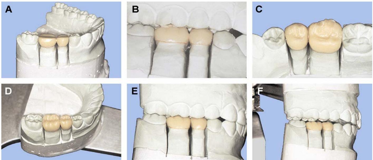
1.41.6.2. Positive waxing, which consists of adding wax to a wax blank (foundation layer, core layer) in small increments and in highly selected areas to form a three-dimensional skeleton of a crown's final contours. Once the wax framework is complete, all that remains is to fill in the spaces between the various parts of the lattice. The obvious difference between this technique and negative waxing is that wax is being built up to produce a given shape instead of being carved back. To positive wax a pattern, use applicable portions of paragraph 1.42 to shape axial surfaces. Then use the wax-added technique presented in Section 1J for the occlusal surface. NOTE: In producing an anatomically and functionally shaped pattern, the choice of negative or positive waxing techniques is up to the dentist. If no specific instructions accompany the case, it is up to the technician.
1.41.7. When carving the junction between the wax and the stone die back to where the preparation begins, use blunt carvers instead of sharpinstruments. Blunt carvers will produce a clean, well-defined margin without marring the die's surface. NOTE: If the wax pattern margins are grossly distorted, remove the pattern and carefully cut it back 2 mm off the margin. Apply a fresh coat of die lubricate to the die and reseat the pattern. Quickly flow molten wax into the space created to cover the margin and provide a smooth internal adaptation.
1.41.8. Smooth and polish the pattern. Use the bristle brush to get at occlusal surface irregularities. Use a piece of silk or nylon cloth wrapped around the end of a finger to smooth axial surfaces.
1.41.9. Recheck MI contact and eccentric movement relationships. Test occlusal contacts by dusting powdered wax on the pattern, bringing the working and opposing casts together, and observing where the pattern wax shows through the dust film. NOTE: Do not use talcum powder in place of zinc stearate for occlusal verification. Talcum powder contains im purities that could cause porosity in the casting.
¶ 1.42. Anatomic Versus Functional Contouring of Wax Patterns
1.42.1. When a pattern is anatomically contoured, the pattern either looks like a natural tooth or it blends well into a natural tooth's surface. Al so, its overall shape and size are proportionally correct in comparison to the teeth around it. Anatomic contouring is done to make prosthesis pleasing to the eye. In contrast, a pattern is functionally contoured when it has proper contact
relationships with opposing teeth in MI and eccentric relations and when the pattern has a size and shape thathelps preserve the health of gingi val tissues. Functional contouring is done so a prosthesis will work well without causing damage toremaining teeth and soft tissue.
1.42.2. In some instances, anatomical and functional shaping of patterns amount to the same thing. As an example, when a pattern’s anatomic proportions look “right ” in comparison to the natural tooth surfaces around it, chances are the resulting casting will help preserve the health of gingival tissues. However, just because the occlusal portion of a pattern looks like the chewing surface of a tooth does not mean it will function without conflict in the patient’s mouth.
¶ 1.43. Labial and Lingual Contours
The buccal and lingual contours should be “flat, not fat.” When the patient eats, the natural contours of the teeth deflect the food. This action stimulates the soft tissues so they will remain healthy. The lip, tongue, and cheek muscles also aid in cleaning the facial and lingual surfaces of teeth. An overcontoured restoration k eeps these self -cleaning m echanisms from working. One of the clues to proper contour can be seen in the em ergence profile of natural teeth (Figure 1.37). Natural teethexhibit a profile that is straight and continues to the height of contour as they emerge from the gingival sulcus. Overcont ouring is extremely hazardous in this area, esp ecially in the interproximal areas.
Figure 1.37. Emergence Profile.
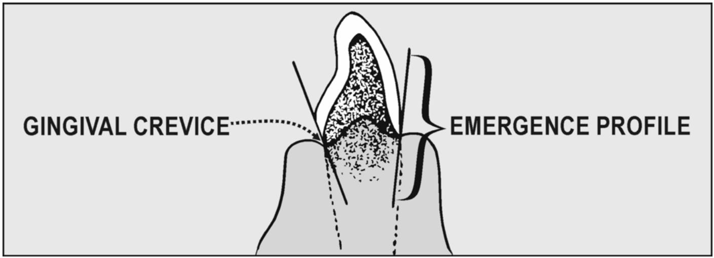
text_image
GINGIVAL CREVICE
EMERGENCE PROFILE
1.43.1. Facial Surface. The facial height of contour of almost all natural teeth is found in the gingival third. These contours rarely exceed 0. 5 mm facially beyond the cementoenamel junction (cervix) and are positioned above the gingival margin (Figure 1. 38). From the bulge, the contour of the facial surface should be flat or sloping inw ard as it enters the crevice and reach es the crown margin (subgingival).
1.43.2. Lingual Surface. The lingual height of contour on most teeth can be seen in the gingival third. Like the facial surface, the height of contour should not project more than 0.5 mm from the cervix. Exceptions to this rule involve the mandibular premolars and molars. Their lingual height of contour is in the middle third. The bulge on mandibular premolars and molars may protrude as much as 0.75 to 1 mm, respectively.
Figure 1.38. Facial and Lingual Heights of Contour of Posterior Teeth.
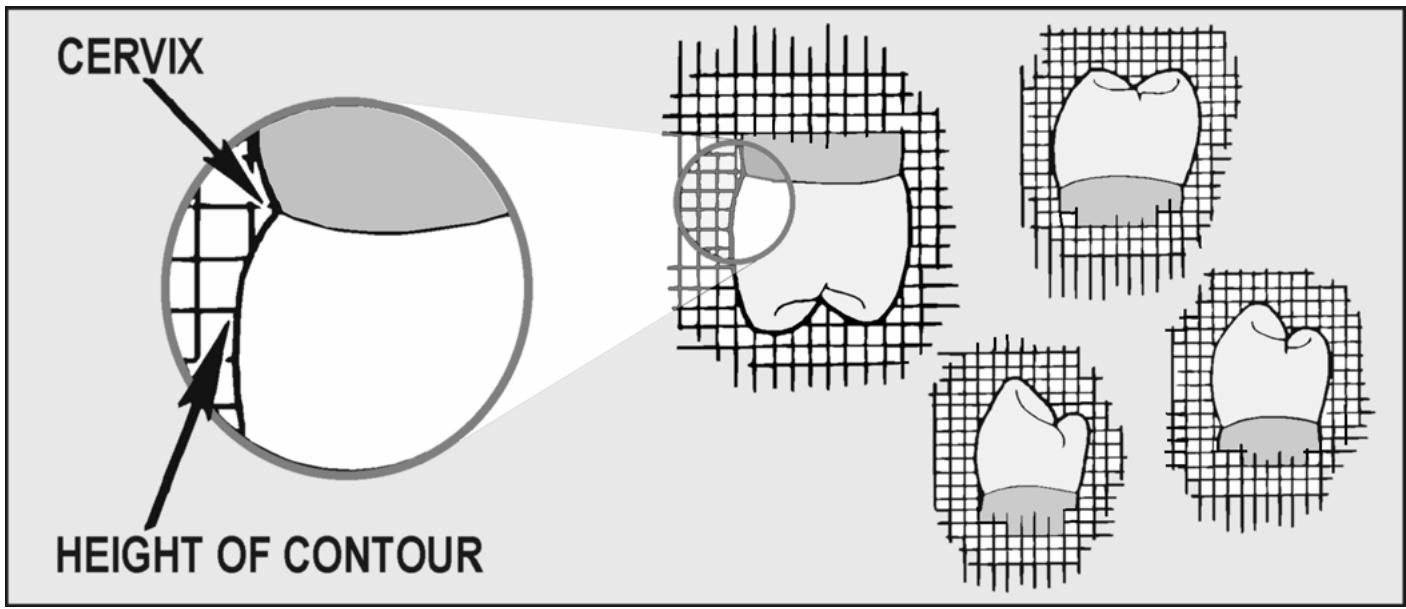
text_image
CERVIX
HEIGHT OF CONTOUR
¶ 1.44. Contours for Intracoronal Restoration Patterns (Inlays)
Negatively wax the pattern. Use the remaining tooth structu re, adjacent teeth, ando pposing teeth as guides for restoring anatomy, adjacent tooth contact relationships, and occlusion. Rem ember that inlays are fully beveled preparations and the entire bevel has to be represen ted in the pattern. For a complete description of contact area placem ent and embrasure shaping, see paragraphs 1.45 and 1.46 for contouring of anterior and posterior extracoronal patterns.
¶ 1.45. Contours for Anterior Extracoronal Restoration Patterns (Partial and Complete Crowns)
1.45.1. Anatomic Contours. Typical anatomic contours for anterior teeth are detailed in Volume 1, Figures 4.36 through 4.38 and 4.43 through 4.45.
1.45.2. Functional Contours.
1.45.2.1. Facial and Lingual Food Deflection Contours. Facial and lingual food deflection contours are detailed in Volume 1, Figures 4.36 through 4.38 and 4.43 through 4.45.
1.45.2.2. Proximal Contact Relationships Among Anterior Teeth. Contacts between adjacent anterior teeth (Figure 1.39) usually occur within the incisal third, mesially. On the distal surfaces of anterior teeth, the contacts are located closer to the junction of the incisal and middle thir ds. Always try to prov ide a contact with adjacent teeth to keep the teeth from moving out of position. However, there are cert ain lim itations to the mesial-distal width of restorations. Avoid making restorations so wide that the patien t has dif ficulty k eeping the restorations clean. If a patient has a natural occurring diastema, it should be provided for in the pattern. Check with the dentist regarding exceptions to the rule of providing proximal contacts.
1.45.2.3. Gingival Embrasures. Accommodate the patient’s interdental papillae in the gingival embrasures. To keep the papillae healthy, do not overcontour the proximal surface of pattern s or place the contact areas too far gingivally. Esthetics of the restoration will g reatly influence the final embrasure form.
Figure 1.39. Proximal Contact Relationships Among Anterior Teeth.
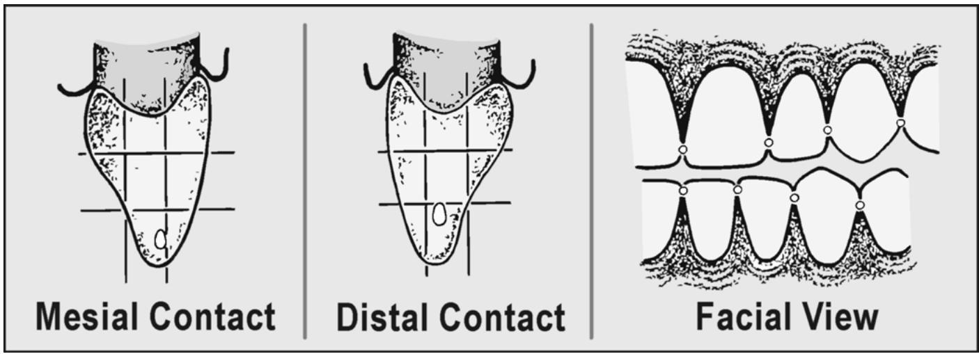
text_image
Mesial Contact
Distal Contact
Facial View
1.45.2.4. Marginal Ridges. Proper contour suggests a harmonious relationship among all teeth—a smooth transition from anterior to posterior within the arch. Therefore, all marginal ridges should contact adjacent teeth at the same height to prevent food im paction and food retention.
1.45.3. Occlusions.
1.45.3.1. Maximum Intercuspation (MI)
Im itate the vertical and horizontal ov erlaps of natural anterior teeth in the vicin ity of the preparation. If this guideline is absent, have the dentist determine the proper overlaps.
1.45.3.2. Working Occlusion. The patien t’s overall occlusion has already been evaluated and decisions made whether the restoration will foll ow them utually protected concept, the group function schem e, or delayed anterior guidance. The lingual aspect of maxillary anteriors and the facioincisal aspect of mandibular anteriors represent the guiding surfaces of anterior teeth. Wax these surfaces to conform to the scheme of occlusion chosen.
1.45.3.3. Protrusive Occlusion. Make the incisal edge of the restoration match the incisal edge contact line formed between the upper and lower an teriors. If this guideline is gone, a rule of thumb for incisor lengthis that upper and lower posterior t eeth should show separation when the anteriors are in protrusive contact. If more specific directions are necessary, check with the dentist.
1.45.4. Pattern Modification for Resin and Porcelain Veneering of the Casting (Windows, Cutouts)
For inform ation on resin veneers, see Chapter 5 of this volum e. For information on metal-ceramic veneers, see Chapter 2 of this volume.
¶ 1.46. Contours for Posterior Extracoronal Restoration Patterns (Partial and Complete Crowns, Onlays)
1.46.1. Anatomic Contours. Typical anatomic contours for posterior teeth are detailed in Volume 1, Figures 4.39 through 4.42 and 4.46 through 4.49.
1.46.2. Functional Contours.
1.46.2.1. Buccal and Lingual Food Deflection Contours. Buccal and lingual food deflection contours are in Volume 1, Figures 4.39 through 4.42 and 4.46 through 4.49.
1.46.2.2. Proximal Contact Relationships Among Posterior Teeth. Contact areas are generally egg-shaped, with the long axis of the “egg” being oriented buccolingually (Figure 1.40). Occlusogingivally, the contact area is located at the junction of the occlusal and middle thirds of a proximal surface. Buccolingually, the contact area can be found at the junction of the buccal and middle thirds of a posterior tooth ’s proximal surface except b etween the maxillary molars, where it is located near the occlusal mesial or distal developmental groove area (Figure 1.41).
Figure 1.40. Posterior Contact Area and Embrasure Characteristics.
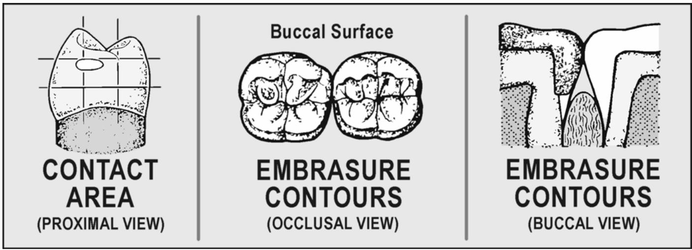
text_image
CONTACT
AREA
(PROXIMAL VIEW)
Buccal Surface
EMBRASURE
CONTOURS
(OCCLUSAL VIEW)
EMBRASURE
CONTOURS
(BUCCAL VIEW)
Figure 1.41. Maxillary and Mandibular Contact Areas (Occlusal View).
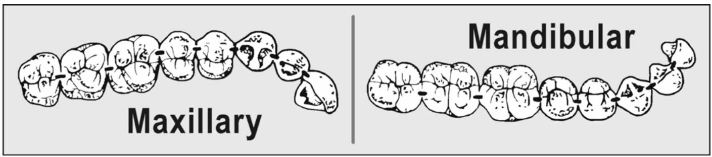
text_image
Maxillary
Mandibular
1.46.2.3. Marginal Ridges. The marginal ridges on both sides of an occlusal embrasure should be oriented at about the same height. Also, marginal ridges are supposed to be rounded so the resulting occlusal embrasure looks like a V-sh aped crevice. Avoid square, sharply angled marginal ridges on adjacent teeth in contact because they produce crack-like occlusal embrasures and improperly placed contact areas.
1.46.2.4. Gingival Embrasures. For interproximal papillae to stay healthy, the natural shape and dimensions of gingival embrasures must still be present after a fixed restoration is cemented in the patient’s mouth. The apex of a gingival embrasure is the result of two convex proximal surfaces com ing together at the contact area. However, the lower p art of the embrasure is formed by diverging, concave proximal surfaces. Reduction of embrasure space with subseq uent com pression of the gingiva happens when the proximogingival surfaces of patterns are overcontoured and when contact areas are located too far gingivally.
1.46.2.5. Buccal and Lingual Embrasures. A contact area is located at the junction of the buccal and middle thirds of a posterior tooth’s proximal surface. As a result, the lingual
embrasure is larger than the buccal embrasure. Because of this relative difference in size, chewing movements will divert most of the food toward the tongue instead of into the buccal vestibule. The tongue moves food back onto the occlusal table for the next chewing stroke more efficiently than the cheek muscle does. Besides the chewing efficiency advantage, proper stimulation of interproximal tissue s requ ires that the lingual embrasure be larger than the buccal.
1.46.2.6. Maximum Intercuspation (MI)
Decide whether the stamp cusp contact in MI will follow the cusp-fossa or cusp-embrasure type of impact. Cusp-fossa imp acts are preferred. Be sure to introduce enough horizontal overlap so the patient does not have a problem with cheek biting. Review Volume 1, Chapter 5.
1.46.2.7. Working Occlusion. Besides making a pattern’s occlusal aspect look like a chewing surface, the pattern’s cuspinclinations along with its ridge and groove direction must be formed in harmony with mandibular movements. A choice among the group function, anterior guidance, and delayed anterior guidance types of occlusion should already have been made. Wax the pattern’s wor king excurs ion rela tionships to conform to the chosen schem e of occlusion. Review Section 1B of this chapter and Volume 1, Chapter 5.
1.46.2.8. Balancing Occlusion. Fixed prosthetic restorations made to oppose natural teeth must not show balancing contacts.
1.46.2.9. Protrusive Occlusion. Posterior teeth are separated bilaterally when the anterior teeth are in protrusive contact.
1.46.3. Wax Pattern Contour Modifications for Resin or Porcelain Veneering of the Casting (Windows, Cutouts)
For inform ation on resin veneers, see Chapter 5 of this volum e; for information on metal-ceramic veneers, see Chapter 2 of this volume.
¶ Section 1J — Wax-Added Technique
¶ 1.47. Overview
The wax-added technique is a method of occlusal surface formation through addition of small increments of wax to a wax blank. (NOTE: Review Volume 1, Chapter 4.) Instead of carving grooves to produce ridges, the ridges are built upin wax. As the ridges are being formed, grooves develop between the ridges by contrast. Some carving may be done in association with the wax-added technique, but only to em phasize and smooth the de pths of the grooves. This method is popularly regarded as the ideal way to organize a m utually protected occlusion, but there is noreason why the technique cannot be used with similar success to organize other kind s of occlusion schem es (group function, delayed anterior guidance). Axial surface and occlusal anatomy are developed by following the standardized waxing sequence in paragraph 1.48.
¶ 1.48. Standardized Waxing Sequence
1.48.1. The first stepin the wax-added technique is to properly shape a wax blank on the die. Wax is applied to the entire die in an even layer to keep distortion to a minimum. Build up the axial surfaces of the blank into their proper facial, lingual, and proximal contours. Leave the occlusal surface out of contact with opposing teeth to allow space for development of the occlusal anatomy.
1.48.2. Place maxillary and mandibular stamp cusp wax cones and check them for clearance in lateral excursions.
1.48.3. Place maxillary and mandibular shearing cusp wax cones and check them for clearance in lateral excursions.
1.48.4. Build up the buccal, lingual, and proximal marginal ridges.
1.48.5. Place the stamp cusp triangular ridges.
1.48.6. Place the shearing cusp triangular ridges.
1.48.7. Verify MI contacts.
1.48.8. Add supplem ental anatomy to fill occlu sal voids and to achiev e any necessary additional occlusal contacts.
1.48.9. Refine the occlusal surface to emphasize the desirable patterns of MI contact.
¶ 1.49. Specific Steps in the Waxing Sequence
1.49.1. Placing Maxillary and Mandibular Stamp Cusp Cones. Place the stamp cusp cones first because they are difficult to see after the shearing cusps and ridges are added (Figure 1.42-A and - B). The stamp cusp cones (lingua l of the upper and buccal of the lower) represent the final position and length of the stamp cusps. When complete, the stamp cusp and associated ridges will account for 60 percent of the total occlusal area.
Figure 1.42. Placement of Maxillary and Mandibular Stamp Cusp Cones.
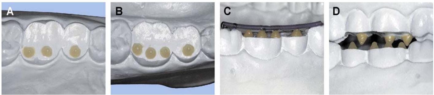
1.49.1.1. Position. Center the stamp cusp cones, representing the vertical dimension holding cusps, over the opposing tooth’s central sulcus area. This helps orient the forces of occlusion more or less parallel to a tooth’s long axis. If a pattern is being waxed against opposing natural teeth, try to make the stamp cusp cone hit in a fossa rather than on the tops of proximal marginal ridges. When waxing one pattern agains t another, place the stamp cusp cones for one pattern over the an ticipated fossa sites on the other. In MI, the id eal is for the tip of a stamp cusp to be supported at three points around an opposing fossa’s rim. Such three-pointsupport is known astripodism (Figure 1.43). Avoid a mortar-and-pestle arrangement in which the cusp tip actually contacts the bottom of the fossa if possible.
1.49.1.2. Length. When waxing against natural teeth, make the stamp cusp cones long enough to hit the opposing tooth in MI. When waxing opposing patterns against one another, make the stamp cusp cones long enough to maintain the anteroposterior curve (Curve of Spee) dictated by the stamp cusps of the unprepared teeth (Fi gure 1.42-C). Once the length of the cones has been established, build up the sides of the fossae on the opposing patterns to meet them.
1.49.1.3. Balancing Excursion Stamp Cusp Relations (Figure 1.42-D)
1.49.1.3.1. Premolars. In a balancing excursion, the stamp cusps of the mandibular first and second premolars pass mesially to the maxillary premolar stamp cusps.
Figure 1.43. Cusp-Fossa MI Contacts.
A. Maxillary stamp cusp contacts ín mandibular fossae
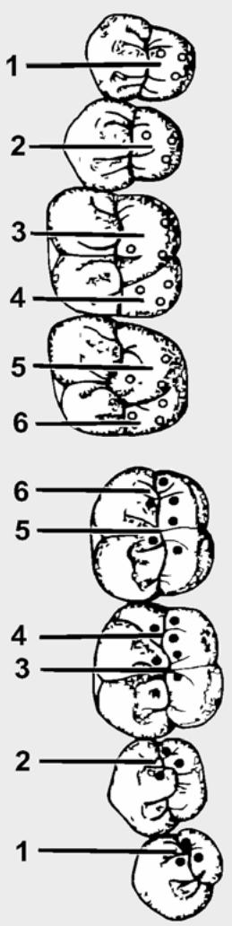
B. Mandibular stamp cusp contacts in maxillary fossae
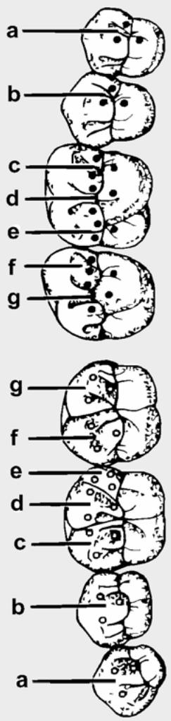
C. Combination of A and B
"INDICATES A CONTACT SHARED BETWEEN A TOOTH'S CUSP AND FOSSA TRIPODS
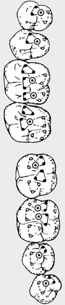
1.49.1.3.2. First Molars. The mesiolingual stamp cusp of the upper first molar passes between the distobuccal and the distal stamp cusps of the lower first molar, div iding the space as equally as possible.
1.49.1.3.3. Second Molars. The stamp cusps of the lower second molar relate to the maxillary second molar’s stamp cusps in the same way as the opposing first molars. The only difference is that the lower second molar pattern might or might not carry a distal cusp.
1.49.2. Placing Maxillary and Mandibular Shearing Cusp Cones (Buccal of the Upper and Lingual of the Lower) (Figure 1.44-A Through –D)
1.49.2.1. Length. Make shearing cusps shorter than stamp cusps to form a proper mediolateral curve (Curve of Wilson) (Figure 1.44-C). Anteroposteriorly, make shearing cusps conform to the desired Curve of Spee.
Figure 1.44. Placement of Maxillary and Mandibular Shearing Cusp Cones.
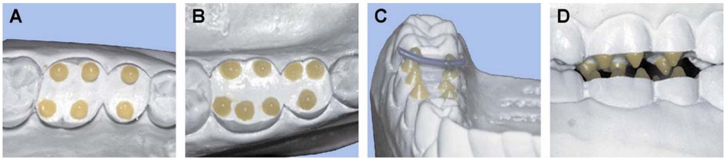
1.49.2.2. Maxillary Shearing Cusp Working Excursion Relations (Figure 1.44-A and -D)
1.49.2.2.1. First and Second Premolars. Make the shearing cusp cones of the uppe r premolars pass distally to mandibular stamp cusps with am ple clearance. In a working excursion, make the shearing cusps of the maxillary premolars travel through opposing embrasures.
1.49.2.2.2. First Molar. The mesiobuccal cusp cone of the upper first molar passes between the mesiobuccal and distobuccal cusp cones of the lower first molar, dividing the space evenly.
1.49.2.2.3. Second Molar. The shearing cusps of the upper second molar are related to the lower second molar in essentially the same way an upper second molar relates to its opponent.
1.49.2.3. Mandibular Shearing Cusp Working Excursion Relations (Figure 1.44-B and -D)
1.49.2.3.1. First and Second Premolars. The lingual cusp cones of the upper first premolar passes distal to the lin gual cusp cone of the lower first premol ar. The lin gual cusp cone of the upper second premolareither passes over or travels behind the lingual cusp cones of the lower second premolar.
1.49.2.3.2. First Molar. The mesiolingual stamp cusp cone of the upper first molar travels between the two lingual cusp cones of the lower first molar, dividing the distance equally.
1.49.2.3.3. Second Molar. The lower second molar shearing cusp cones are placed in the same relation to the upper second molar as the lower first molar is to the upper first molar.
1.49.3. Waxing the Peripheral Marginal Ridges (Figure 1.45-A Through -D and Figure 1.46)
The peripheral marginal ridges consist of buccal, lingual, and proximal segments. The buccal and lingual marginal ridges are composed of the mesial and distal cusp ridges of a tooth’s buccal and lingual cusps, respectively. Each posterior tooth has mesial and distal proximal marginal ridges. A proximal marginal ridge is sepa rated into buccal and lingual parts by a groove or “sluiceway.” Sluiceways are escape routes for food during ch ewing and allow for stim ulation of lingual interproximal gingival tissue. Control of buccal and lingual peripheral marginal ridge height is an important influence on the schem e of occlusi on you want to develop. If buccal and lingual peripheral marginal ridges are waxed sono contact occurs with opposing cusp ridges or inclines in lateral excursions, the case is anterior guided. If mandibular buccal peripheral marginal ridges are waxed into working side contact with the lin gual inc lines of maxillary bucca l cusps, grou p function results, as follows:
Figure 1.45. Placement of Marginal Ridge Segments.
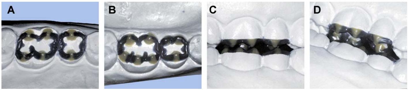
Figure 1.46. Marginal Ridge Contours (Buccal View).
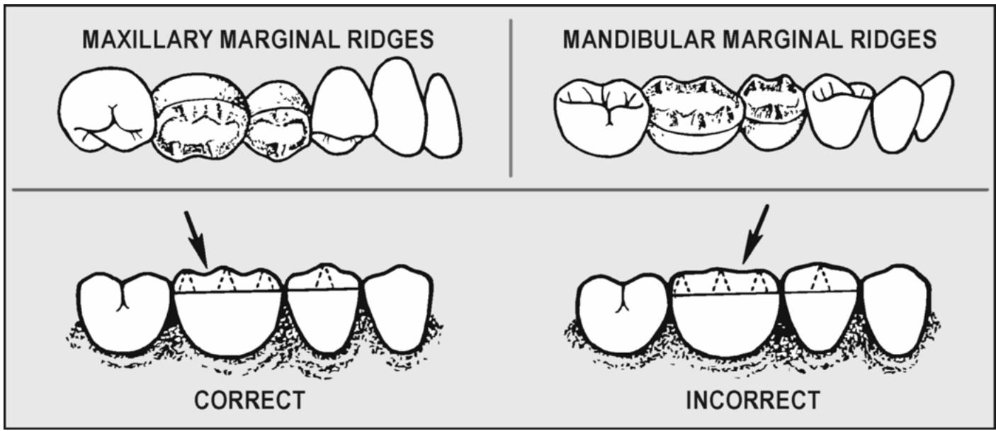
1.49.3.1. Proximal Surface Peripheral Marginal Ridges and Opposing Cusps (MI)
1.49.3.1.1. Cusps to Fossa Stamp Cusp Orientations. In this type of MI, all stamp cusps occupy fossae and the cusp tips have “tripod” support within the fossae. A proximal marginal ridge forms onewall of a proximal fossa (mesial or distal fossa). When a stamp cusp hits in a proximal fossa, one of the tripod contacts occurs on a proximal marginal ridge (Figure 1.43). The other two tr ipod contacts occur on stamp and shearing cusp triangular ridges yet to be laid down. NOTE: When a stamp cusp hits in a central fossa, all three tripod contacts are foundon various triangular ridge inclines.
1.49.3.1.2. Cusp to Embrasure Stamp Orientations. In the cusp-embrasure concept of MI, most of the mandibular buccal cusps hit across two opposing proximal marginal ridges that form an embrasure. Almost all of the maxillary lingual cusps are in a fossa relationship with mandibular teeth. (See Volume 1, Chapter 5 and Figure 5.4, for details.) Be sure there are no interferences between proximal surface periph eral marginal ridges and opposing cusps during lateral movements.
1.49.3.2. Maxillary and Mandibular Lingual Peripheral Marginal Ridges (Working Excursion Relationship)
The convention is to wax oppos ing lingual peripheral marginal ridges and cuspinclines out of contact when the teeth are in a working relationship. This is true for group function and mutually protected occlusions.
1.49.3.3. Maxillary and Mandibular Buccal Peripheral Marginal Ridges (Working Excursion Relationship)
1.49.3.3.1. Mutually Protected Occlusion. Mandibular buccal peripheral marginal ridges pass by all parts of the maxillary buccal cusps with clearance.
1.49.3.3.2. Group Function. Buccal peripheral marginal ridges of mandibular teeth contact the lingual inclines of buccal cusps and the buccal peripheral marginal ridges of maxillary teeth.
1.49.3.4. Maxillary Lingual and Mandibular Buccal Peripheral Marginal Ridges (Balancing Excursion Relationship)
There will be no contact of any kind between opposing posterior teeth during the progress of a balancing excursion.
1.49.4. Positioning Maxillary and Mandibular Stamp Cusp Triangular Ridges (Figure 1.47- A and -B)
Figure 1.47. Placement of Stamp Cusp and Shearing Cusp Triangular Ridges.
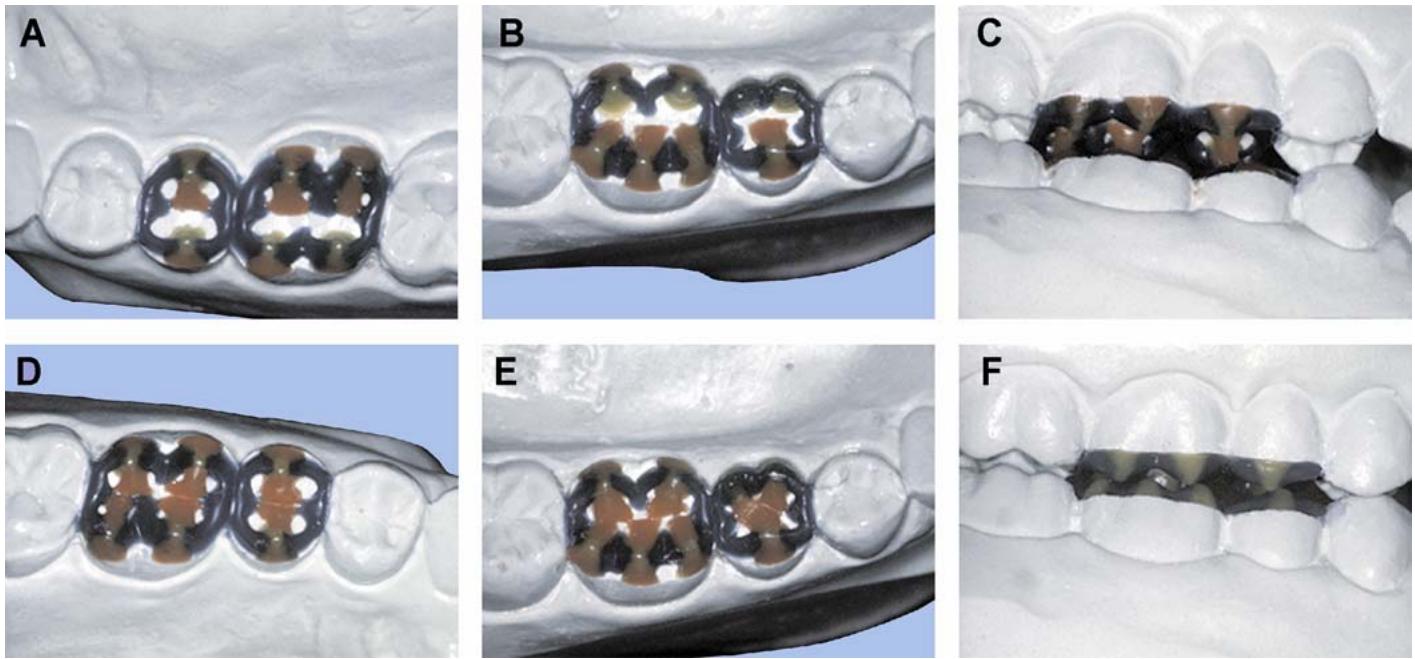
1.49.4.1. MI Contacts. The MI fossa contacts that should develop as a result of this step appear in Figure 1.43. The contacts form where the stamp cusp triangular ridges in one arch touch the opposing stamp cusp triangular ridges.
1.49.4.2. Balancing Excursion Relationships. There should be no balancing excursion contact between any surface of opposing stamp cusps (Figure 1.47-C). Stamp cusp triangular ridges must be waxed in specific directions to allow escape of the opposing stamp cusps out of the central sulcus area with no interferences during a balancing move ment. To achieve this goal, maxillary stamp cusp triangular ridges are angled toward the distal of the tooth as they trav el from a cusp tip to the central sulcus. Mandibular stamp cusp triangular ridges angle toward the mesial of mandibular teeth as they travel from cusp tip to ce ntral sulcus. Also, on teeth having multiple stamp cusps, the junction of triangular ridge inclines form s a com paratively d eep valley of groove to allow escape of an opposing stamp cusp.
1.49.5. Positioning Shearing Cusp Triangular Ridges (Figure 1.47-D and -E)
1.49.5.1. MI Contacts. The MI fossa contacts that should develop as a result of this step appear in Figure 1.43. The contacts occur because stamp cusp marginal ridges (lingual marginal ridges of the maxillary posteriors and facial marginal ridges of the mandibular po steriors) tou ch opposing shearing cusp triangular ridges.
1.49.5.2. Working Excursion Relationships. In a working excursion, the mandibular shearing cusps are supposed to miss the maxillary stamp cusps (Figure 1.47-F). In the case of a group function occlusion, the maxillary shearing cusp triangular ridges would show working excursion contact with mandibular buccal cusp mesial and distal cusp ridges. When the occlusion is anterior guided, maxillary shearing cusps would miss the mandibular stamp cusps during a working movement. To achieve the recommended working and balancing relations, the following information becomes important:
1.49.5.2.1. Recall how the stamp cusp triangular ridges were angled when they were laid down. Shearing cusp triangular ridges travel at roughly a 90-degree angle from the cusp tip to the central sulcus area.
1.49.5.2.2. The intersection of a stamp cusp triangular ridge and a shearing cusp triangular ridge produces a characteristic Gothic arch or arrow point angle. The apex of this angle is directed toward the distal in the maxillary arch and toward the mesial in the mandibular arch (Figure 1.48)
Figure 1.48. Stamp Cusp Working and Balancing Paths Out of a Fossa MI.
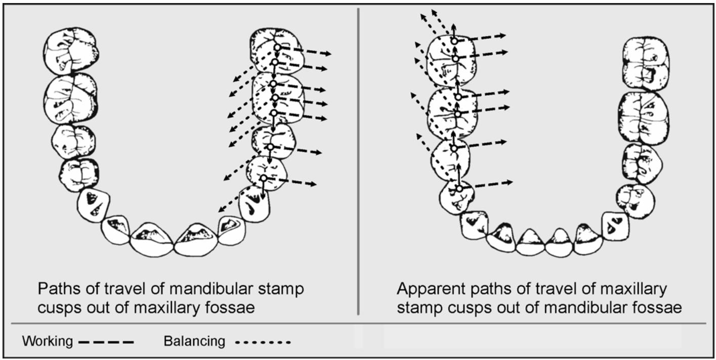
1.49.5.2.3. If stamp cusps are to move laterally out of their respective fossae without interference, triangular ridges must be waxed in arrow point patterns that parallel the working and balancing paths taken by the stamp cusps.
1.49.6. Verifying MI Contacts. At this time, all contacts are required for proper tripodism of the stamp cusps and should be present. Figure 1.43-C shows the three-point contact of stamp cusps within fossae (solid lines). It also shows where the three points of contact occur around the rims of individual stamp cusps (dotted lines). A contact is shared where two triangles overlap.
1.49.7. Waxing Supplemental Anatomy (Figure 1.49)
Supplemental anatomy is used for the following two purposes:
1.49.7.1. To fill any occlusal surface voids that still remain.
1.49.7.2. To provide any additional contacts that might be needed to achieve stamp cusp tripodism. The most common situation for this is when a pattern is waxed against an opposing natural tooth. This is because you have no control over the natural tooth’s shape and the wax pattern has to be adapted to existing, unalterable conditions.
Figure 1.49. Placement of Secondary Anatomy and a Cross-Section View of Cusp Placement.
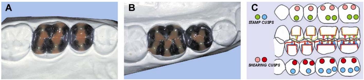
¶ Section 1K — Casting Production
¶ 1.50. Overview
This section describes casting, spruing, and finishing procedures for conventional crown and FPD gold alloys. Casti ng procedu res formetal-ceramic substructures are described in Chapter 2 of this volume.
¶ 1.51. Rules of Casting
Every casting contains porosity, due to solidification shrinkage. The task is to control the location of that porosity, keeping it out of the casting and in the sprue or reservoir system. To do this, apply the following rules:
1.51.1. Attach the pattern sprue to the thickest cross-sectional area of the wax pattern. The flow of molten alloy from the reservoir to the pattern should be from regions of greater volume to areas of lesser volume.
1.51.2. Position the pattern margins to the right and mark their location with an orientation dot. In centrifugal casting, the wax patterns should be positioned so their margins face to the right to take advantage of the centrifugal, rotational, and gravitational forces on the molten metal.
1.51.3. Position the wax patterns so they will be located in a cold zone of the investment mold and the reservoir in the heat center (thermal zone) of the ring. That way, the castings will cool first, the sprues will cool next, and, finally, the rese rvoirs will cool, thereby pla cing the por osity in the reservoir that cools last.
1.51.4. Provide a reservoir withenough molten alloy to fill the shrinkage that occurs within the casting.
1.51.5. Do not cast a button if you are using a runner bar or other method of indirect spruing. The exposed surface of a button causes the buttonto cool before the casting, drawing molten metal away from the reservoir and reducing the feed of molten alloy to the castings.
1.51.6. Eliminate sharp turns, restrictions, points, or impingements on flat surfaces that increase turbulence in the sprue. The pathways for the flow of metal must be smooth, gradual, and without impediments. Any restrictions can accelerate the metal’s rate of flow and lead to abrasion of the mold (mold wash).
1.51.7. Select a casting ring of sufficient diameter and length to accommodate the patterns to be invested. The investment layer surrounding the patterns should be a uniform thickness to ensure proper mold expansion and thick enough to prevent investment breakage.
1.51.8. Apply a wetting agent to the wax pattern s to reduce the surface tension of investment. By cleaning the wax surfaces of contaminants and covering the wax patterns with a wetting agent, bubbles on the casting will be less likely to occur.
1.51.9. Measure all investment liquids and weigh all casting investment powder for a precise liquid-powder ra tio. Sm all va riations in the liq uid-powder ratio greatly a ffect expansion of the investment.
1.51.10. Elim inate the air in the investment by vacuum mixing and careful pouring of the investment into the casting ring.
1.51.11. Allow the investment to set completely before beginning the burnout procedure. If setting is not complete when the ring is placed in the oven, the mold will be weak and may break during burnout.
1.51.12. Use a burnout technique that is specific for the type of patterns used (wax versus plastic) and suitable for the particular alloy selected. Plastic sprues need to be heated slowly so they soften and do not exert pressure and possib ly break the mold. The burnout temperature for each casting alloy varies and must be adjusted to ensure adequate expansion and a complete cast.
1.51.13. Use an adequate heat source to properly melt and cast the alloy selected for use. Inadequately heated alloy does not attain maximum fluidity and may not fill the mold completely. Normally, you will notice blunt margins when the alloy is cast too cool. Too much heat can burn off minor alloying elements through volatilization, oxidation, or both. Symptoms may be brittle or porous castings.
1.51.14. Use the reducing zone (middle portion) of the flame to melt the alloy and not the oxidizing zone (outer portion) when torch casting. The oxidizing portion of the flame can introduce oxygen and carbon into the alloy and adversely affect its properties.
1.51.15. Follow the manufacturer’s recomm endation on casting procedure and casting force. Whether you use a centrifugal, v acuum, or pressure casting, t oo much force can be just as detrimental as insufficient force.
1.51.16. Direct alloy flow to your margins. In a centrifugal casting machine, the metal will flow downward and to the right first. Position the casting ring to take advantage of this behavior.
1.51.17. Do not quench the ring immediately after casting. Quenching the casting ring before the metal and investment have completely cooled can result in tensile forces being applied to the casting by the investment. With premature quenching, the metal is still too hot to posses s sufficient strength toresist these forces so the casting can tear. NOTE: Many alloy manufacturers do not recommend quenching the casti ng ring at all. Instead, they recommend allowing the ring to completely bench cool.
1.51.18. Refer to Table 1.1 for the consequences of not obeying the rules of casting.
Table 1.1. Rules of Casting.
| ITEM | Probable Cause | Penalty | Solution |
| 1 | Spruing to thin areas to reach thicker areas | Cold shuts, short margins, or incomplete castings | Attach sprues to thickest cross-sectional areas of pattern. |
| 2 | Pattern or casting ring not oriented to trailing edge of casting arm | Cold shuts, short margins, or incomplete castings | Indicate placement of pattern margins in ring and place ring in casting machine so margins face downward and to the right. |
| 3 | Patterns place in thermal zone | Shrinkage porosity | Place patterns in cold zone and locate reservoir in heat center. |
| 4 | No reservoir or reservoir too small | Shrinkage porosity or suckback porosity | Use reservoirs that are larger than, or at least equal to, the thickest cross-sectional areas of the pattern. |
| 5 | Too much metal used, resulting in a large button | Shrinkage porosity, suckback porosity, or distortion during porcelain firing | Weigh the wax patterns and sprues to calculate amount of metal required. (Technique based on specific gravity of wax versus casting alloy.) |
| 6 | Turbulence created by rough sprue network | Voids or surface pitting | Eliminate sharp turns, restrictions, points, or impingements on flat surfaces. |
| 7 | Casting ring too small or too many patterns in one ring | Mold fracture, casting fins, or shrinkage porosity | Space patterns 6 mm apart with at least 9 mm of investment between patterns and ring liner. Cover patterns with at least 6 mm of investment. |
| 8 | Wetting agent not applied to patterns | Nodules | Brush or spray patterns with wetting agent and let dry. Excess amounts cause rough castings. |
| 9 | Investment powder or liquid not measured | Ill-fitting castings | Weigh all casting investment powder and measure investment liquids. Use the proper ratio of each. |
| 10 | Investment not vacuum mixed | Weak mold or distorted castings | Vacuum mix and carefully pour investment into rings to ensure a dense, bubble-free mold. |
| 11 | Investment not completely set | Mold cracking, blowout, or fins | Allow investment to set completely prior to burnout. |
| 12 | Improper burnout techniques used | Cold shuts, short margins, or cold welds | With plastic patterns, use two-stage burnout to soften plastic. Set high temperature according to alloy manufacturer's recommendations. |
| 13 | Inadequate heat used to melt and cast alloy or too much heat used | Cold shuts, short margins, cold welds, or rough castings | Use heat source capable of melting the alloy to sufficient fluidity for complete mold fillings. |
| 14 | Oxidation zone used instead of reducing zone | Gas porosity or altered coefficient of thermal expansion | Use reducing zone to melt alloy. |
| 15 | Not enough casting force or too much force | Cold shuts, short margins, cold welds, mold fracture, or fins | Use casting machine manufacturer’s instructions on winding arm or applying vacuum/pressure. |
| 16 | Casting ring quenched prematurely | Hot tears | Allow the ring to bench cool completely before quenching. |
¶ 1.52. Spruing
The sprue is a channel through which molten metal will be cast into the mold. The purposes of a sprue channel are to allow an escape for wax during the early stages of the burnout procedure and to direc t the molten metal from the c rucible into the mold cavity. The chann el also provides a reservoir of molten metal on which the casting may draw during solidification. Sprue formers are made of wax, plastic, or metal; and they attach the wax pattern to the sprue base. When the sprue former is burnedout, it becomes the sprue through which molten metal will be cast.
1.52.1. Size of the Sprue Former.
1.52.1.1. The sprue former should be smooth, short, and thick (6 to 9 mm long and 8 to 10 gauge in diameter)
The size of the sprue former will increase with the size of the patter n. Molten metal will first cool and solidify near the walls of the mold and sprue, form ing a crus t around a molten center.
1.52.1.2. The metal will shrink towards this crus t as the molten center co ols, leaving avoid in the last part of the metal to so lidify. This void is called “sh rink spot porosity.” When using a long, thin sprue former, molten metal will freeze in the sprue channe l before it solidifies in the crown portion of the mold. As a result, the casti ng part of the mold cannot draw on a reservoir of fluid metal in the sprue channel to compensate for cooling shrinkage. Shrinkage porosity will then occur within the crown.
1.52.1.3. When using a sprue former of correct size, molten metal will continu e to be drawn into the mold as cooling progresses, and shrink spot porosity will occur in the sprue or reservoir instead.
1.52.2. Attaching the Sprue Former to the Pattern (Figures 1.50 and 1.51)
1.52.2.1. To lessen the possibility of distorting the pattern, always attach the sprue former while the pattern is seated on the die. Attach the sprue former to the bulkiest part of the pattern at an angle that will create the least amount of casting turbulence (45 degrees to the axial surfaces of the pattern). Avoid attaching sprue former to anatom ical features that are critical to the occlusion you have developed (stamp cusp tips, fossae).
1.52.2.2. When attaching metal or plastic sp rue formers, never heat the sp rue former and plunge it into them ass of the pattern because the pattern will warp. In stead, jo in the sp rue former to the pattern with a small beadof sticky wax. Blend the sprue former into the pattern with additional inlay wax. Before taking the sp rued pattern off the die, add a small amount of wax to the contact areas to compensate formetal loss during finishing.
1.52.3. Attaching the Sprued Pattern to the Sprue Base (or Crucible Former) (Figure 1.51- B)
Remove the sp rued pattern from the die. Lute the sprue former to the sprue base, building up or reducing the apex of the sprue base until the sprue former’s lengthis 6 to 9 mm and there is 6 mm clearan ce between the top of the pattern and the rim of the casting ring. This space is the thickness of investment needed to prevent metal from breaking out of the mold while casting is in progress. Yet, it is thin enough to let trapped gases escape ahead of molten metal entering the mold cavity.
Figure 1.50. Examples of Direct Spruing.
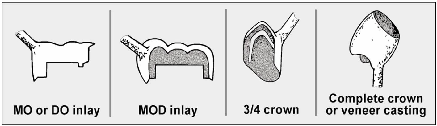
text_image
MO or DO inlay
MOD inlay
3/4 crown
Complete crown
or veneer casting
Figure 1.51. Directly Sprued Wax Pattern Attached to a Sprue Base.
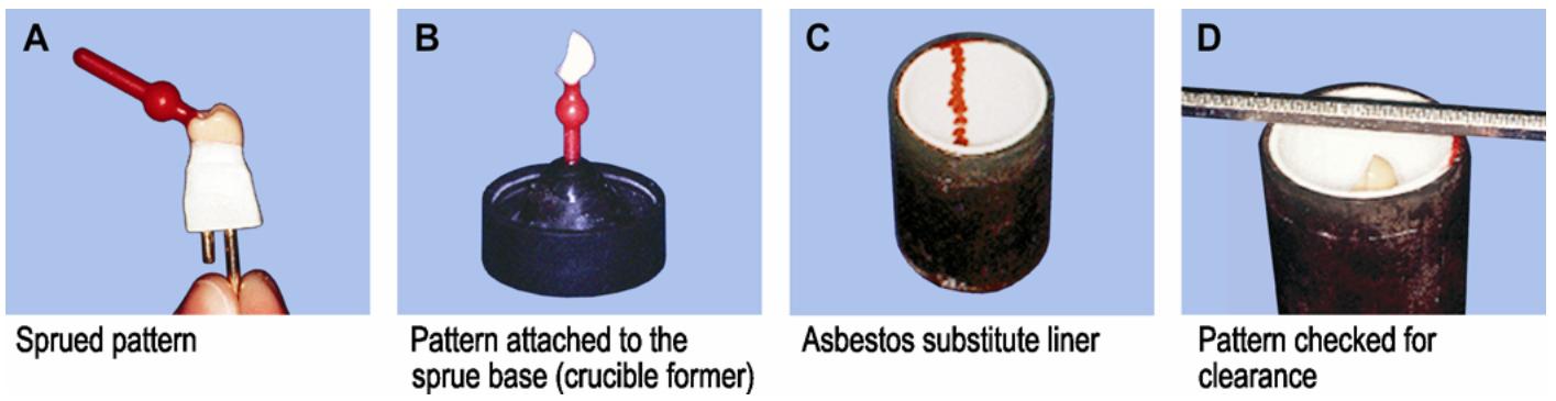
1.52.4. Spruing Options. Most single unit castings can be made with one direct sprue former— the only spruing option mentioned so far. A straight, uninterrupted sprue channel between the crucible and the mold characterizes direct spruing. However, below are a few more spruing options:
1.52.4.1. Auxiliary Spruing a Single Pattern (Figure 1.52)
For large patterns or those patterns with two thick areas sep arated by a thin area, use auxiliary sprue formers (18-gauge wax) to ensure complete casting.
1.52.4.2. Direct Spruing of Multiple, Independent Patterns. When two or more patterns are sprued in direct fashion off of the same sprue base, they should fan out from around the apex of the sprue base. Do not make the sprue former’s leadoff one another. When using prefabricated sprue formers with reservoirs, place the reservoirs so they contact each other and are positioned in the center of the ring (thermal zone). Join the contacts between the reservoirs with inlay wax.
1.52.4.3. Indirect Spruing of Multiple, Joined Patterns.
1.52.4.3.1. Indirect spruing is commonly used to cast multiple single units or units joined together as a splint or a FPD. In contrast to direct spruing, the sprue channels for indirectly sprued patterns do not lead directly from the crucible to the mold.
Figure 1.52. Auxiliary Spruing of Single Patterns.
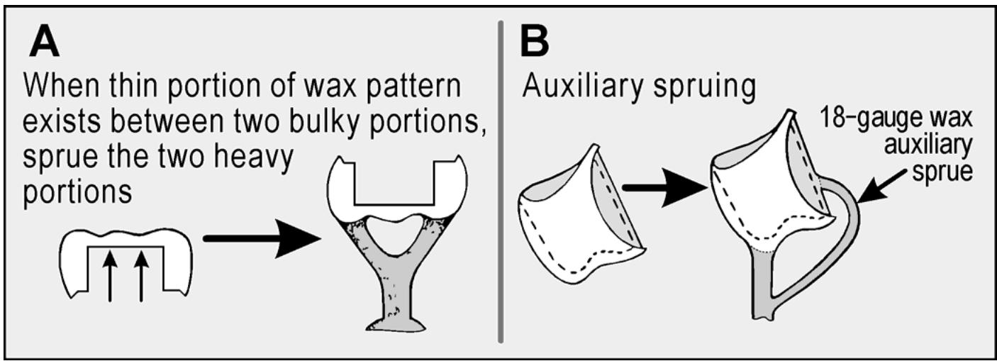
1.52.4.3.2. Figure 1.53 illustrates indirect spruing techniques for three unit FPD substructures. Note that the 10-gauge patterned sprue formers from the horizontal runner bar to the pattern are offset from the 8-gauge lead sprue formers that connect the runner bar to the sprue base. The runner bar is also made of 8-gauge round wax.
Figure 1.53. Indirect Spruing of Multiple Joined Patterns.
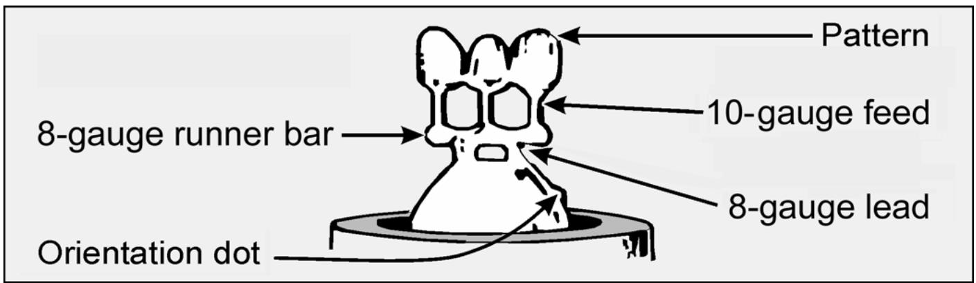
text_image
Pattern
10-gauge feed
8-gauge runner bar
8-gauge lead
Orientation dot
1.52.4.3.3. This spruing technique allows molten metal to be cast into the mold so it fills the mold uniformly and simultaneously, thus eliminating variations that occur when molten metal hits different areas of the mold at different times. Indirect spruing increases turbulence (over the direct method) and reduces backpressure when the metal is cast into the mold. It helps eliminate shrink spot porosity because the feed of molten metal stays open longer.
1.52.4.4. Indirect Spruing of Multiple, Independent Patterns (Figure 1.54)
A number of patterns that are not joined together are sprued to a runner bar (as described in the paragraph 1.52.4.3).
1.52.4.5. Sprued Pattern Orientation Dot. Investigations have shown that the flow of the molten metal is downward and to the right of the mold (trailing edge) as it rotates in a centrifugal casting machine. Mark the mold so it can be oriented to the arm of the casting machine to take advantage of this flow of molten metal. The two kinds of patterns that receive maximum benefit from selective orientation of the mold in the casting machine are as follows:
Figure 1.54. Indirect Spruing of Multiple Independent Patterns.
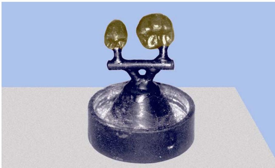
natural_image
Close-up of a metallic object with two round gold-like objects mounted on top, resembling a balance scale (no text or symbols visible)
1.52.4.5.1. Single Unit Patterns With a Thin Section. Place a small round do t of wax on the sprue base. Position the pattern so the thinnest section (or margins) faces the dot of wax. This dot will late r app ear in the investment and be used to orient the mold to tra il as the casting arm spins.
1.52.4.5.2. Splints and FPDs Being Cast in One Piece. Place a dot of inlay wax on the sprue base in line with the side of the pattern (Figure 1.53). This leaves a dimple in the investment. Use the dimple to orient the ring in the casting machine. If using a horizontal machine, position the length of the pattern verti cally. Also, the facial surfaces of the pattern should trail as the casting arm spins. If usi ng a vertical machine, orient the pattern horizontally.
1.52.5. Prepare the Casting Ring for Investing (Figures 1.51 and 1.55)
1.52.5.1. Line the casting ring with one layer of dry resilient material (asbestos substitute, trade name Nobestos or Kaoliner), keeping it 3 mm short of the crucible (sprue base) end of the ring with the small locking dimple exposed that prevents shifting of the investment. The ring liner should be flush with the top of the ring so expansion will be even and unrestricted. NOTE: Commercial ring liner materials are made of either cellulose, which burns out in the oven, or ceramic (ka olin), which remains in the r ing after burnout. Ceram ic liners a re not m oistened prior to investing because they will not absorb water.
1.52.5.2. Tack the ring liner in place with a small amount of sticky wax. Moisten the liner so it will not a bsorb wate r from the investment and cha nge the investment’s expansion characteristics. Some manufact urers recomm end you not wet ring liners. The liner acts as a cushion against the different investment expansions that occur, an insulator agains t the loss of heat during the casting operation, and an aid in removing the investment from the ring after the casting has been made.
1.52.5.3. Paint the pattern with a wetting agent and gently blow away any excess. Seat the dimpled end of the casting ring in the sprue base, being very careful not to disturb the pattern.
Figure 1.55. Schematic View of a Sprued Pattern in a Casting Ring.
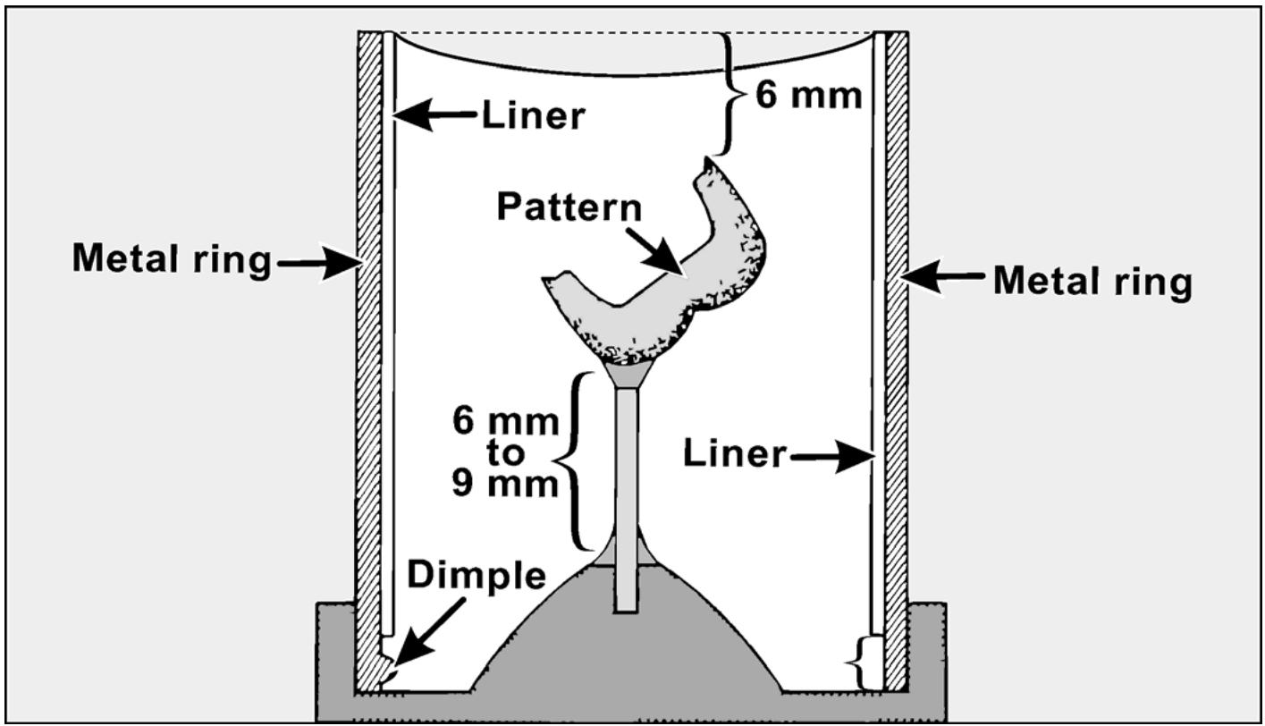
text_image
Metal ring
Liner
6 mm
Pattern
6 mm to 9 mm
Dimple
Liner
Metal ring
¶ 1.53. Venting a Sprued Pattern
Venting is a special provision that permits gas to escape rapidly from the mold cavity ahead of incoming molten metal during the casting procedure (Figure 1.56). There are “direct” vents (attached directly to patterns) and “blind” vents (not attached). Current theory states that direct vents act more like chill sets and are of lesser im portance than “vents” that remove gases. Chill sets are wax projection s that radiate heat away fr om the castings and cause the metal to coo l in a desirable w ay. The term chill vent better describes the use of direct venting. In Figure 1.54, two 18- gauge wax rods have been placed on the pontic area of the FPD. Pontic areas are bulky and chill vents should help to control porosity.
Figure 1.56. Vented Pattern.
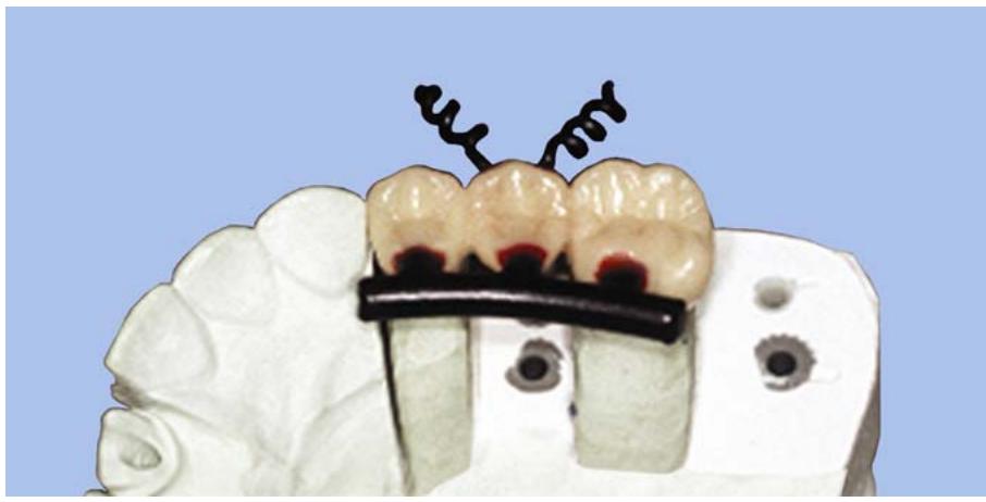
natural_image
Dental model showing dental implants mounted on a human head, no text or symbols visible
¶ 1.54. Investing
A sprued pattern is invested in a casting ring by pouring inve stment material into the ring.
1.54.1. Maintaining Cleanliness. Keep all equipment and hand instruments used in the investing operation meticulously clean. Keep sprue bases, spatulas, mixing bowls, mechanical mixers, and water baths free of any dried or caked investment. A high percentage of porosity in gold castings can be attributed to investment contam ination. Particles may also cau se the inves tment to set improperly, causing it to be soft and crumble when hot molten metal is cast into the mold. Porosity is also caused by investment powder that has ab sorbed m oisture from the envir onment. It is important to store investment in a tightly cove red container. Herm etically sealed bags withindividual portion of investment are best.
1.54.2. Choosing a Compensation System for the Shrinkage of Cooling Gold (Gypsum-Bonded Investments Only)
Cast gold shrinks about 1.4 percent (± 0.2 percent) when it solidifies from the molten state, and investment expansion compensates for this shrinkage. Depending on how they are handled, investments can expand in a number of ways:
1.54.2.1. Kinds of Investment Expansions.
1.54.2.1.1. Semihygroscopic or Effective Setting Expansion. This setting expansion (about 0.35 percent) occurs in air when the casting ring contains a wet ring liner.
1.54.2.1.2. Hygroscopic Expansion. This setting expansion (about 0.75 percent) occurs when the invested pattern is completely immersed in a warm water bath.
1.54.2.1.3. Thermal Expansion. Therm al expansion of the investment and moldoccurs when it is heated in a burnout oven. Higher heat results in more thermal expansion.
1.54.2.2. Two Popular Systems of Compensating for Cast Gold Shrinkage.
1.54.2.2.1. High Heat Technique. In this system, most of the investment expansion is heat induced. The investment bench sets in ai r for 45 minutes during which sem ihygroscopic expansion of 0.35 percent occurs. The pattern wax is then burnedout at 1250 F, during which thermal expansion of 1.2 percent occurs. Total expansion for high heat technique is 1.55 percent.
1.54.2.2.2. Hygroscopic Technique. (NOTE: Most of an investment’s expansion is hygroscopic.)
1.54.2.2.2.1. First, the investment sets under 100 oF water for 30 to 45 minutes, during which hygroscopic expansion of 0.75 percent occurs. Pattern wax expansion from room temperature (72 oF) to 100 oF is 0.3 percent. Then, the pattern is burnedout at 900 oF, during which thermal expansion of 0.55 perc ent takes place. Tota l e xpansion of the hygroscopic technique is 1.60 percent.
1.54.2.2.2.2. Advantages claimed for the hygroscopic compensation methodover the high heat technique are that themethod gives smoother castings, prolongs the life of furnaces and casting rings, and gives finer grain structure to the solidified gold.
1.54.2.2.2.3. Some brands of investment are specially compounded for use in the hygroscopic method while others w ork best in the high heat techni que. Always read the manufacturer’s directions.
1.54.3. Preparing the Water and Investment Powder. Use the water-to-powder ratio recommended by the manufacturer. Recommended ratios will fall within a narrow range. When selecting from this range, keepin mind that less water in the mix will give greater mold expansion.
1.54.3.1. Distilled Water. The water should be carefully measured. Using only distilled water, prewet the bowl. (NOTE: A significant percentage of the water can be consumed in wetting the mixing bowl and not become incorporated into the mixed mass.) Do not leave excess water on the surface of the bowl, but be sure it is damp. W ater temperature should be about 70 F. Room temperature water can vary according to the area within the laboratory and the season of the year. Water that is too war m or too cool is one of the greatest con tributing factors to the distortion of the wax pattern during the investing process. Use only distilled water.
1.54.3.2. Investment Powder. If not using a prepackaged investment, be sure to weigh the investment powder accurately.
1.54.4. Investing a Pattern. There are two basic ways to invest a pattern—mechanical mixing the investment under vacuum and hand-mixing (investing). No matter which method you use, the first step is to pour water into the mixing bowl and then slowly add the powder. Incorporate the powder and water with a hand spatula sono dry powder or large lumps are visible.
1.54.4.1. Mechanical Mixing Under Vacuum (Figure 1.57)
1.54.4.1.1. After incorp orating the powder and water with a hand spatula, place the lidon the bowl and ensure it is tightly closed.
1.54.4.1.2. Connect the vacuum tubing. Slip the metal trap cap at the e ndof the tubing into its opening on the top of the lid.
1.54.4.1.3. Position the vacuum spatulator so the agita tor’s drive nut e ngages them otor’s drive chuck. Star t the unit. Spatulate for the length of time recommended by the manufacturer (Figure 1.57-A). Then disengage the spatulator.
Figure 1.57. Investing With a Vacuum Spatulator.
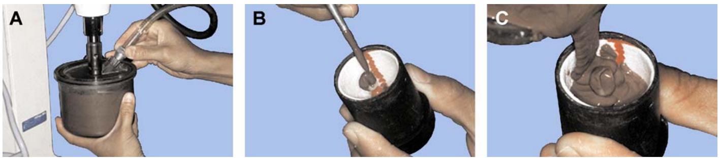
1.54.4.1.4. Release the vacuum, but let the unit run for 1 more minute to flush water vapor from the pump and re-oil the motor.
1.54.4.1.5. Use a brush or instrument and mild vibration to flow a mix of investment over all the pattern ’s surfaces and into the cavity of the pattern (Figure 1.57-B). Take care not to incorporate air bubbles. Do not touch the patt ern with the brush or instrum ent. Instead, vibrate a brush loadof investment ahead of the brush’s bristles until the pattern is covered. When done properly, precoating a pattern in this way helps ensure a bubble-free casting.
1.54.4.1.6. Place the ring carefully on the sprue base and pour the investment around the pattern (Figure 1.57-C)
This is done by pourin g investment down the side of the ring and allowing it torise around the pattern. While the ring is being filled, hold it in the hand that is restedon the vibrator plate. The vib rations cause the ring to fill evenly without trapping air. If the hygroscopic technique is being used, submerge the ring in a water bath (Figure 1.58). If not, let the investment bench set.
1.54.4.1.7. Wash mixer parts, lid, bowl, and hand spatula thoroughly under running water before the investment has a chance to set.
Figure 1.58. Hygroscopic Expansion Water Bath.
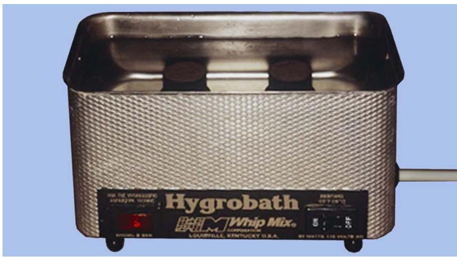
text_image
Hygrobath
Whip Mix.
LEGENDILLE, KENTUCKY U.S.A.
1.54.4.2. Hand-Investing. If powered mechanical spatulators and vacuum equipment are not available, a pattern can be hand-invested as follows:
1.54.4.2.1. Place the mixing bowl on a vibrator and spatulate the contents with a hand spatula. The vibration causes the mix to stay in the bottom of the bowl and facilitates thorough mixing. Mild vibration will also act to remove most air bubbles.
1.54.4.2.2. At the very least, most laboratories have a hand-driven mechanical spatulator. If using one of these devices, start the mix with a hand spatula and finish it with the hand-cranked unit. The number of turns of the handle is important. Follow the manufacturer’s directions because d ifferences in the amount of spatulation cause v ariations in setting expansion. Gently vibrate the mix to liberate trapped air.
1.54.4.2.3. The investment can now be added to the ring as described in paragraphs 1.54.4.1.5 and 1.54.4.1.6.
1.54.5. Investment Setting Time.
1.54.5.1. Investment Destined for High Heat Pattern Burnout. A minimum setting time of 45 minutes (1 to 1.5 hours is best) is critical to developing sufficient semihygroscopic setting expansion and ensuring adequate strength. Be sure the invested pattern is allowed to standon a bench where there is no vibrati on. If the investment is subjected to v ibration during the initia l setting period, a cracked mold or rough casting can result.
1.54.5.2. Hygroscopic Investment Expansion. After investing (and while the investment is still wet), submerge the ring in 100 oF water for 45 minutes. It may remain in water up to 3 hours. Do not subject the investment to vibration while it is setting.
1.54.6. Removing the Sprue Base and Sprue Former.
1.54.6.1. Once the investment has set for the recommended length of time, carefully twist off the sprue base in a single motion and free it from the investment and sprue former. Remove any excess investment from the ends and side of the ring so it will fit properly in the casting machine.
1.54.6.2. Break the glaze at the top of the ring so gases generated by pattern burnout can escape readily (Figure 1.59)
Ensure the crucib le portion of the mold is clean and free of loose investment particles.
Figure 1.59. Breaking the Top Surface Glaze of the Set Investment.
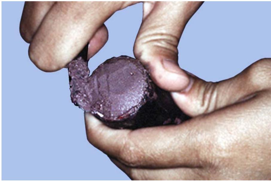
natural_image
Close-up of hands holding a dark, texturedobject against a blue background (no text or symbols visible)
1.54.6.3. Metal sprues formers must be removed before wax pattern burnout; wax and plastic sprue formers do not. Toremove a metal sprue former, warm it through contact with a hot pair of pliers, invert the casting ring with the crucible downward, and rotate the sprue former out of the mold with the plie rs. From this point until the casting is made, keep the ring inverted to prevent particles of investment or other debris from falling into the sprue hole. Deb ris in the mold causes gross casting defects.
1.54.7. Storing Invested Patterns.
1.54.7.1. Invested patterns usually go directly into the burnout oven after the investment sets. Occasionally, though, invested patterns cannot be burnedout imm ediately so they must bestoredovernight or longer.
1.54.7.2. Do not let set investments dry out. Water must be present in the investment to conduct heat evenly throughout a mold. When a mold is dry, the outer edges nearest the heated furnace walls can become much hotter than the mold’s inner core. The investment may c rack under these conditions.
1.54.7.3. Store invested patterns in a humid atmosphere. Wrap them in a damp towel and keep them in a plastic bag that contains a few drops of water. If a ring dries out, soak it in water for 10 or 15 minutes before placing it in a burnout furnace.
¶ 1.55. Wax Elimination (Burnout)
1.55.1. Overview. Wax elimination (burnout) is used to eliminate all moisture from the invested ring. It is also used to eliminate the wax or plastic used to form the pattern from the mold cavity. The heat expands the mold cavity to compensate for alloy shrinkage during solidification and cooling and raises the mold to the proper temperature to receive molten alloy. Controlled burnout prevents damage to the investment from overheating. Uncontrolled burnout causes breakdown of the mold’s walls and possible sulfur contamination of the alloy. Sulfur contamination renders the alloy weak and brittle.
1.55.2. Calibrating the Burnout Furnace’s Temperature Indicator.
1.55.2.1. Every burnout furnace should have a good pyrometer and indicator. The pyrometer (or thermocouple) consists of a pair of dissimilar wires welded together at the couple tip. The wires project into the furnace’s burnout chamber (muffle). Contamination of the wires by gases released in the muffle and exposure to continued high temperatures changes the thermocouple’s behavior characteristics.
1.55.2.2. Because the thermocouple is directly responsible for the readings on the temperature indicator, the readings tend to lose their accuracy. Therefore, temperature readings should be checked monthly. One method is to use a commercially prepared pellet made fr om metal oxides. The pellet fuses and flows when its melting poin t is reached. The accuracy of these pellets is within 1 percent of their rated melting temperatures. Pellets may be obtained that melt at almost any temperature up to 2400 F. The pelle ts com e from the manufacturer with f ull directions for use.
1.55.3. Placing Rings in the Furnace.
1.55.3.1. Make sure the ring is damp when placing it in the furnace to minimize the possibility of cracking. Soak rings that have driedovernight (or longer) in water for 15 minutes before placing them in the furnace.
1.55.3.2. Place a tray in the bottom of the muffle for the rings to sit on. The tray will retain the molten wax that flows out of the mold cavity and keep it from soaking through the muffle floor where it could damage the heating element. An alternative is to line the floor of the muffle with asbestos-substitute strips.
1.55.3.3. Place the rings in the center of the furnace toward the back wall when possible (Figure 1.60)
The temperature in different parts of the o ven may vary and this placement ensures that the furnace atm osphere surrounding the ring is the same as that recorded by the pyrometer indicator.
Figure 1.60. Placement of Rings in the Burnout Furnace.
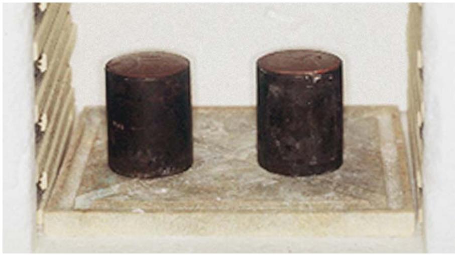
natural_image
Two dark cylindrical objects placed on a wooden surface, no visible text or symbols
1.55.3.4. Place the mold in the oven with the sprue hole down. Elevate one edge of the ring upward by resting it on a small piece of ceramic material. (This is not necessary if the burnout furnace has a firing pla tform with channels in it.) Molten w ax will flow out of the mold as it melts and air will pass more freely into the mold cavity to ensure complete burnout ofall residual carbon.
1.55.4. Controlling Burnout Time and Temperature.
1.55.4.1. High Heat Technique. Use the high heat technique with investments that have bench set in air and semihygroscopically expanded. The burnout temperature is 1250 to 1275 °F Starting with a cool oven, the furnace takes about 1 hour to reach burnout temperature. After reaching burnout temperature, heat soak the mold for ano ther hour. Total time in the oven is about 2 hours. Do not raise the temperature above 1300 °F because it will cause the investment material to break down, which causes rough castings. Excessive burnout temperatures also produce sulfur gases that mix with gold alloys and make castings brittle. Do not use the oven to burn out new molds until its temperature has dropped to at least 900 °F
1.55.4.2. Low Heat Technique. Low heat burnout is used in combination with investments that have been hygroscopically expanded in a water bath. The burnout temperature is 900 °F. Heat the mold from room temperature to 900 °F or place it directly in the furnace at 900 °F. After reaching burnout temperature, heat soak the mold for 1 hour. Total time in the oven is about 2 hours when starting with a room temperature furnace. However, only half the time is needed with a preheated furnace. Some claim low heat burnout produces finer grained, stronger castings than the high heat techn ique. Using equipment at lower temperatures generally prolongs its life.
1.55.4.3. Factors Influencing Burnout Time and Temperature. Do not rush burnout. If an error is made in burnout time, be sure it is on the long side rather than on the short side, as follows:
1.55.4.3.1. Temperature Rise Time. The time from room temperature to the desired burnout temperature should not be less than 1 hour.
1.55.4.3.2. Number and Size of the Molds. Allow an additional 10 minutes for each additional mold. (Use an additional 20 minutes for larger molds.) Calculate burno ut time from the time the last mold is placed in the oven.
1.55.4.3.3. Preheated Oven. Using a preheatedoven does not significantly decrease burnout time. At the start of the burnout cycle, the temperature of the investment is much lower than the atm osphere of the furnace. The time it would take the mold to reach the preheated temperature is about the same as the time it would take a room temperature oven and mold torise simultaneously to the preheated temperature. Therefore, burnout time stays about the same whether the ring is initially placed in a room temperature furnace or in a preheatedoven.
1.55.4.3.4. Plastic Patterns. Molds containing plastic patterns must burn out slower and longer. The initial burnout temperature should not exceed 600 °F for the first 30 minutes.
¶ 1.56. Casting With a Gas-Air Torch and Centrifugal Casting Machine
(NOTE: There are more sophisticated, electrical methods of melting and casting gold alloys. If you are going to use an electrical device in the casting process, be sure to follo w the manufacturer’s directions for operating the equipment.) This method uses direct application of heat with a blowtorch to melt an alloy before casting as follows:
1.56.1. Balance the Machine. Keep a “dummy” casting ring available to balance the casting machine.
1.56.2. Prepare the Crucible. There are three types of available casting crucibles; clay, quartz, and aluminum oxide. Clay crucibles must be glazed by sprinkling powdered flux inside them and heat with a casting torch. The alternative approach would be to sim ply use a quartz or alum inum oxide crucible. These crucibles are self-glazing if they are sufficiently heated with a torch.
1.56.3. Determine the Amount of Alloy Needed. The amount of alloy required for a casting is dictated by the pattern’s weight. Ideally, you should not cast a button when using a reservoir. A button is any additional cast alloy beyond the sprue. To determine the amount of alloy needed, weigh the patterns with attached sprue former. Then multiply that weight times the specific gravity of the alloy being used. The product is the amount of alloy needed to cast. For example,.6 grams (weight of patterns and sprue former) times 15.5 (specific gravity of the alloy) equals 9.3 grams. Thus, you would cast 9.3 grams of alloy.
1.56.4. Select the Metal Needed. Use either new alloy or a combination of new alloy and previously cast alloy for a casting. Do not mix brands or types of alloy because the physical properties of such blends are unpredictable. When using previously cast alloy, combine it with at least 50 percent new gold alloy. Thoroughly microblast previously cast alloy before reusing it. When necessary to combine small pieces of alloy or remove impurities from a button, melt the alloy in a depression on a charcoal block with the reducing part of a blowtorch flame. Sprinkle a reducing flux over the molten metal to remove the oxides and impurities. Prevent reoxidation by shutting off the air to the torch and playing the gas flame over the alloy to exclude air until the alloy solidifies.
1.56.5. Wind the Casting Machine. Allow three to four turns to generate enough casting force. Use more turns for small masses of metal and a lower number for large masses. Raise the stop rod from the base of the machine and rest them ain arm against it. The press ure of the arm holds the rod in an elevated position. The arm will not rotate as long as the stop rod is up.
1.56.6. Adjust the Torch Flame.
1.56.6.1. Good casting torches usually have two control valves, one for air and the other for gas (natural gas or propane)
Be sure the hoses supplying the torch are connected to the correct gas sources. Light the torch with only gas flowing. Incorporate progressively more air into the gaseous mix until a pointed flame showing two “cones” develops (Figure 1.61). The outer cone, called the redu cing zone, is the part of the flame that c onsists of burning gas. The inner cone, called the combustion zone, is unburned gas of a low temperature.
Figure 1.61. Parts of a Gas-Air Torch Flame.
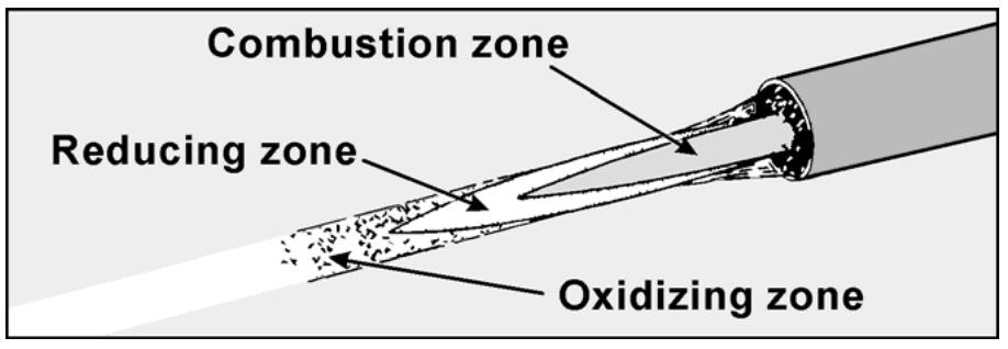
text_image
Combustion zone
Reducing zone
Oxidizing zone
1.56.6.2. Melting must be done in the reducing z one of the flame lying between the tips of the inner andouter cones. This portion should be large enough to cover the button of gold alloy used.
1.56.6.3. Taken as a whole, the flame should al ways have a reducing nature. This means the flame has a supply of gas somewhat larger than the available air can completely burn. If the flame does not have this reducing character, excess oxygen will oxidize base metals in the alloy and raise the alloy’s melting te mperature to a poin t where it is impossible to melt it satisfactorily.
1.56.7. Preheat the Crucible. Preheat the crucible with the torch. This ensures a cold spot does not develop at the base of the alloy as it is being melted.
1.56.8. Melt the Gold and Apply Flux. Place the required amount of alloy in the preheated crucible. Melt the alloy with the reducing zone of the flame. If a significant oxide film forms, sprinkle a small amount of casting flux onto the surface of the alloy. If the metal is clean and uncontaminated, this should be the only time you use flux. Never add flux once the ring has been positioned in the casting machine. The rush of gas out of the torch could blow the flux into the mold and cause it to become part of the casting.
1.56.9. Position the Ring in the Casting Machine (Figure 1.62)
Maintain the alloy in as molten a state as po ssible. Remove the burnedout mold from the oven. In sert the ring into the machine with the sp rue hole tow ard the cruc ible and ens ure the orientation dot is positioned toward the trailing edge of the rotation of the casting machine. Move the crucible into contact with the ring.
1.56.10. Heat the Alloy to Casting Condition. The exact time of casting the alloy into the mold cavity is determined by appearance. The gold alloy is ready to cast when it exhibits a mobile, bright, mirror-like surface.
1.56.11. Make the Casting. Grasp the arm of the machine firmly, move it away from the stop rod, and let the rod drop back into the base. Release the arm and make the cast, hold ing the flame on the gold until the crucible starts torotate. Release the casting arm smoothly. Do not allow it to jerk because molten metal spills can result.
1.56.12. Recover the Casting From the Mold. When the machine stops spinnin g, remove the mold and place it on a bench top. Allow it to bench cool completely before dives ting. Push the investment out of the ring and break away the bulk of investment surrounding the castings.
¶ 1.57. Cleaning and Pickling (Deoxidizing) the Casting
1.57.1. Cleaning. Use a stiff brush under running water to remove adhering investment. A microblaster with glass beads under low pressure may also be used to remove investment from the outer casting surface, while alum inum oxide may be used to remove investment from the inner casting surface. Use cau tion not to u se too much air pressure or abrade the margins of the casting with the microblasting process (Figure 1.63).
1.57.2. Pickling (Figure 1.64)
1.57.2.1. Pickling consists of chemically removing oxides from a casting. A 50-percent solution of hydrochloric acid is freque ntly used for pickling. Also, there are various kinds of commercial pickling preparations available. Because these comm ercial preparations are generally safer than hydrochloric acid solution, their use is recommended.
1.57.2.2. Place the pickling solution in a porcela in pickling dish. Using plastic-co ated tongs, submerge the casting. Heat the solution, but do not let it boil.
Figure 1.62. Melting the Gold Alloy and Positioning the Ring in the Casting Machine.
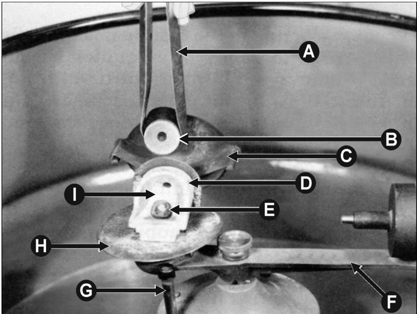
text_image
A
B
C
D
E
I
H
G
F
A. Tongs
B. Casting ring
C. Cradle
D. Crucible
E. Molten gold
F. Casting arm
G. Stop rod
H. Crucible carriage
I. Asbestos liner
1.57.2.3. After the casting brightens, take it out of the pickling agent with the plastic-coated tongs. NOTE: Using inert plastic or plastic-coated tongs is important because the plastic material has no effect on the casting. When using ordinary metal tongs or forceps, an undesirable copper deposit forms on the casting’s surface.
1.57.2.4. Wash the casting with a solution of sodi um bicarbonate, liberally rinse in clear water, and dry. Because undesirable deposits form on a casting if the pickling solution is dirty, be sure to change the solution often in relation to the usage rate.
1.57.2.5. An alternative method of pickling involves placing the casting in a plastic bag filled with solution and then in an ultrasonic cleaner for about 10 minutes. This will remove remaining investment particles and lightly clean the casting of surface oxides.
Figure 1.63. Microblasting Process.
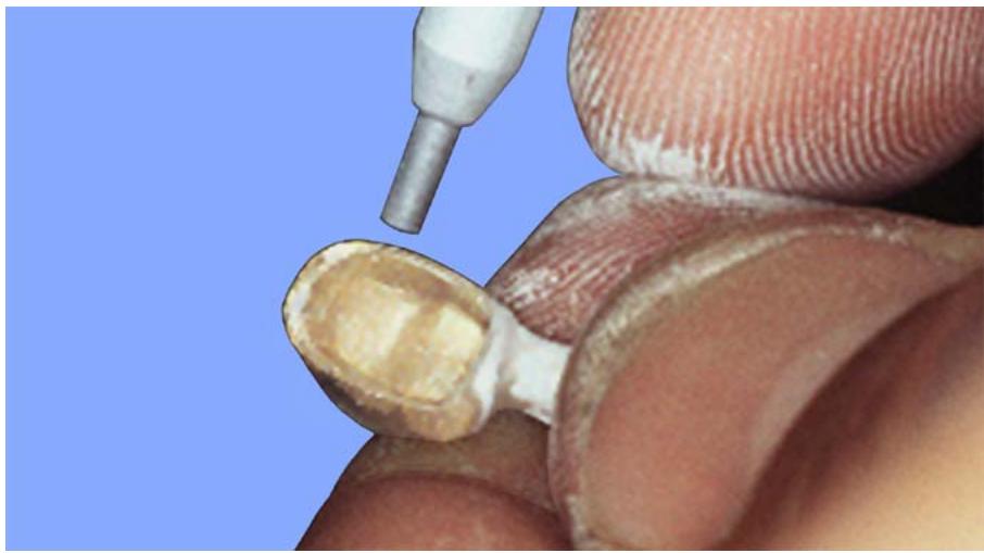
natural_image
Close-up of a dental implant or tool being placed on a human body, showing a metallic tip and a small yellow-brown component against a blue background (no text or symbols visible)
Figure 1.64. Pickling a Casting.
natural_image
Close-up of a white ceramic pot with green seed inside, placed on a black woven base against a blue background (no text or symbols visible)
1.57.3. Safety Hazards Associated With Pickling.
1.57.3.1. Almost all pickling solutions are poten tially dangerous. They burn skin, ruin clothes, and corrode equipm ent. Keep all pickling soluti ons in c learly labe led, plas tic bottles with plastic caps.
1.57.3.2. When making an acid pickling solution, ALWAYS pour the acid into the water. NEVER pour the water into the acid because the chemical reaction is violent and the acid will splatter. The antidote for an acid burn is to apply baking soda to the affected area im mediately after contact. In the absence of a specific chemical neutralizer for a pickling agent, the best course of action is to liberally flush the affected area with water.
1.57.3.3. One of the first rules of safety during the pickling procedure is to wear protective eyeglasses. Do not boil pickling agents; they tend to foam and splatter unexpectedly when boiled. A thermostatically controlled electric heater will eliminate this hazard. Leave the lidon the pickling dish as much as possible and work under a power exhaust hood because the vapors generated by a pickling solution are toxic.
¶ 1.58. Finishing and Polishing the Casting
The finishing of a casting cons ists of inspecting the casting for defects, removing the sprue, test-fitting the casting on the die, rough-finishing the casting’s surface, checking the contact areas, adjusting the occlusion, and polishing (Figure 1.65-A through 1.65-L):
1.58.1. Inspecting the Casting for Defects. If possible, use magnification to check the casting ’s surfaces. The casting should be smooth, dense, and complete. There are two major kinds of defects to look for, positive and negative. Bubbles of metal or fins that protrud e from a casting’s surface are called positive defects. Poros ity, holes, and incomplete castings are classified as negative defects. Holes can sometimes be soldered clos ed. Porosity and incomplete castings usually means starting over. Before a casting can be test-fittedon its die, free the internal surface of the casting ofall positive defects. It is highly recommended that a m icroscope is used in this process. Remove nodules and fins with a round carbide bur of adequate size in relation to the defect. Never grindor polish a casting’s internal surface.
1.58.2. Removing the Sprue. Remove sprues with a separating disk (Figure 1.65-A). Be careful to avoid cutting into the body of the casting or damaging the fine margins. Leave a little of the sprue on the casting to permit proper recontouring of the area.
1.58.3. Test-Fitting the Casting on the Die. Examine the internal surface of the casting for positive defects under microscopic view and eliminate any defects (Figure 1.65-B). After all internal surface positive defects have been removed, carefully place the casting on the die (Figure 1.65-C). There is serious potential for die damage when a casting is test fitted. If a casting does not fit, don’t force it because the pattern cannot be remade if the die is damaged. The casting should seat completely without undue pressure. It should bestable on the die and the margin of the casting should conform perfectly to the margin of the die. If the casting does not seat, try to determine the cause and check for positive defects that might remain. If the casting is warpedor otherwise distorted, reject it and s tart over. Once the casting is accu rately seated on the die, go to the next step.
1.58.4. Rough-Finishing the Casting’s Surface.
1.58.4.1. Finishing and polishing can be done rapidly and effectively only by well-organized use of progressively finer abrasive and polishing agents. Be careful not to damage the casting.
1.58.4.2. Shape the sprue stump into the general contour of the casting with a heatless stone (Figure 1.65-D) followed by a #203 stone.
1.58.4.3. Sharpen the occlusal anatomy by using a small, dulled round bur (Figure 1.65-E)
1.58.4.4. Go over the entire casting with fine stones (Figure 1.65-F) and rubber abrasive wheels (Figure 1.65-G) and points (in that order)
Depending on the roughness of the casting, start with the finest abrasive that does the job. Sm oothand contour all axial surfaces, from the tips of the cusps to within 1 mm of the margins. Be careful not to grind away proximal contours in contact areas. This could cause loss of contact with adjacent teeth and/or loss of contact with opposing teeth.
1.58.5. Adjusting Proximal Contacts. When a casting has mesial and distal proximal contacts, adjust them one at a time. At the time the working cast was made, the natural teeth adjacent to a preparation site were also made removable with dowel pins. Place the die in the working cast, remove one of the teeth next to the die, try to seat the casting on its die, and carefully remove contact excess with a ru bber abrasive wheel. Us e a piece ofarticulating film between the crown and adjacent teeth to d isclose excessive contact areas (Figu re 1.65-H). After the casting seats, follow the same procedure for the other contact. Finally, check the proximal contacts with both adjacent dies in place to ensure proper contact (Figure 1.65-I).
Figure 1.65. Finishing and Polishing a Casting for Try-In.
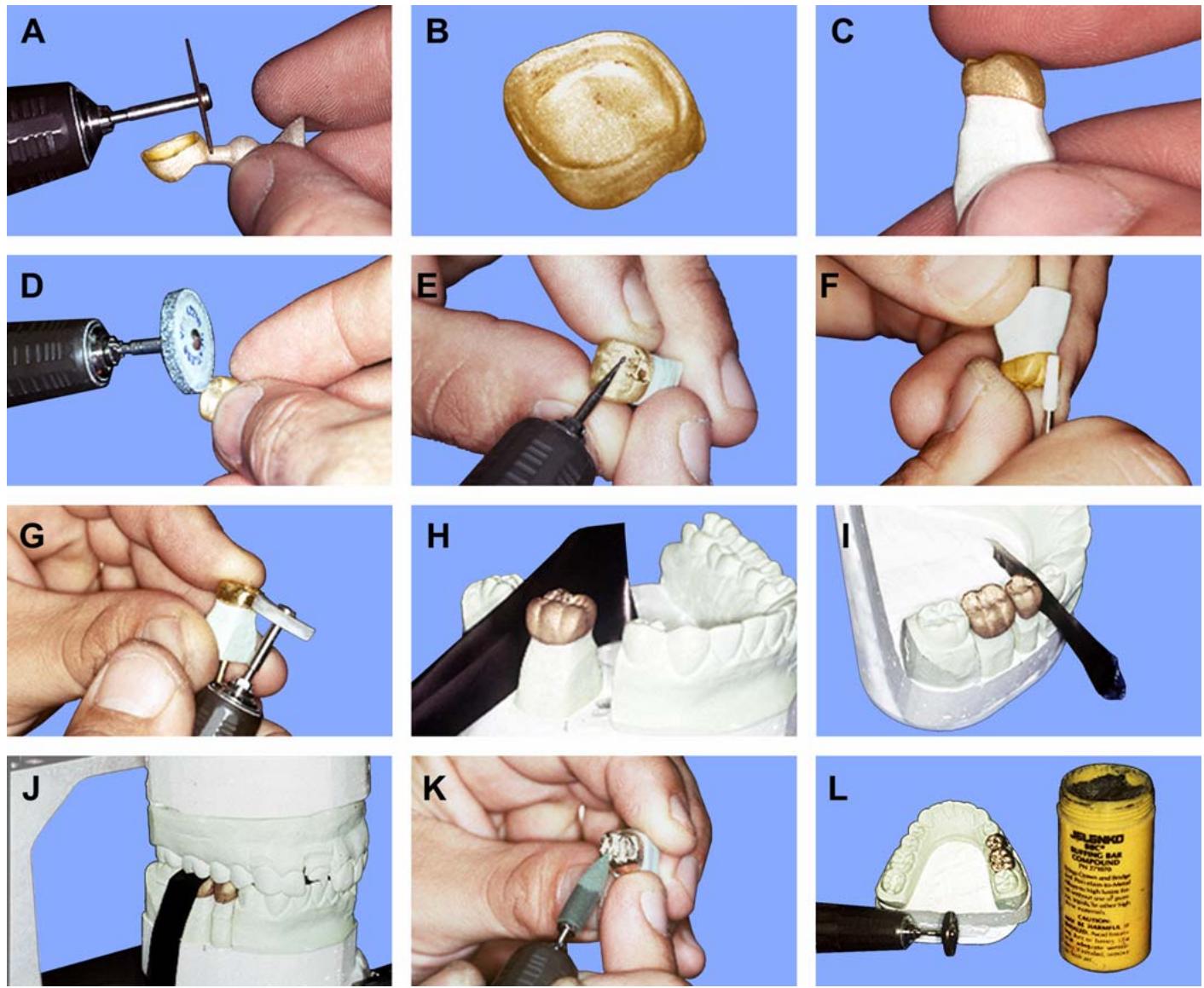
1.58.6. Adjusting the Occlusion. Place each working cast in position in the articulator. Seat the casting on the die. Restore the vertical dimension of occlusion first. Use articulating film to disclose high spots on the casting (Figure 1.65-J). Preserve the occlusal anatomy when grinding these spots. After re storing the v ertical d imension of occlusion, check the casting’s eccentric relations with opposing teeth. The casting should c onform to the occlusion schem e chosen for the wax pattern (anterior guidance, group function, etc.). Maxillary stamp cusps should not contact between upper and low er teeth on the balancing side. Perform a final smoothing of the casting with rubber wheels and points (Figure 1.65-K). Re member to stay about 1 mm a way from the margins.
1.58.7. Polishing the Casting. The materials used for final polishing are buffing bar compound (BBC), rouge, soft bristle brushes, and (sometimes) mandrel mounted felt wheels and a chamois. The BBC and rouge are polishing agents used together with an appropriate wheel or brush to shine a casting. BBC is the coarser of the two. Polishing starts with BBC on a soft bristle brush or felt wheel and continues with rouge on a soft bristle brush or felt wheel (Figure 1.65-L). An extremely high luster results when rouge is applied to a casting with a chamois wheel.
1.58.7.1. Preliminary Polish. The dentist will try the casting in the patient’s mouth after the occlusion has been corrected in the articulator and will probably modify the proximal contacts and adjust the occlusion. In effect, a casting is finished and polished twice—once before andonce after the try-in. The casting’s occlusal surface is the portion most likely to be modified. It makes sense to anticip ate this and not carry polishing of the occlusal surface to com pletion before try-in. For a pre-try-in polish, high shine all axial surfaces and leave a satin finish on the occlusal. Some dentists prefer a matte-finishe docclusal surface becau se it is easier to see interferences on a casting in the patient’s mouth against a dull background than a shiny one. The matte finish is produced with a mini-sandblaster.
1.58.7.2. Final Polish (Figure 1.66)
1.58.7.2.1. Remove any gross scratches the dentist might have produced and give the casting its final polish. If the dentist did not finish the margins during try-in, the technician will do sonow.
1.58.7.2.2. Some technicians finish the margins with the casting seated on the die; others prefer to finish them off the die. Neither method completely assures the margins will not be abraded, so use extreme care. WHEN FINISHING AND POLISHING MARGIN AREAS, ALL ROTARY INSTRUMENTS USED MUST REVOLVE PARALLEL TO THE MARGINS (Figure 1.66).
Figure 1.66. Final Polish.
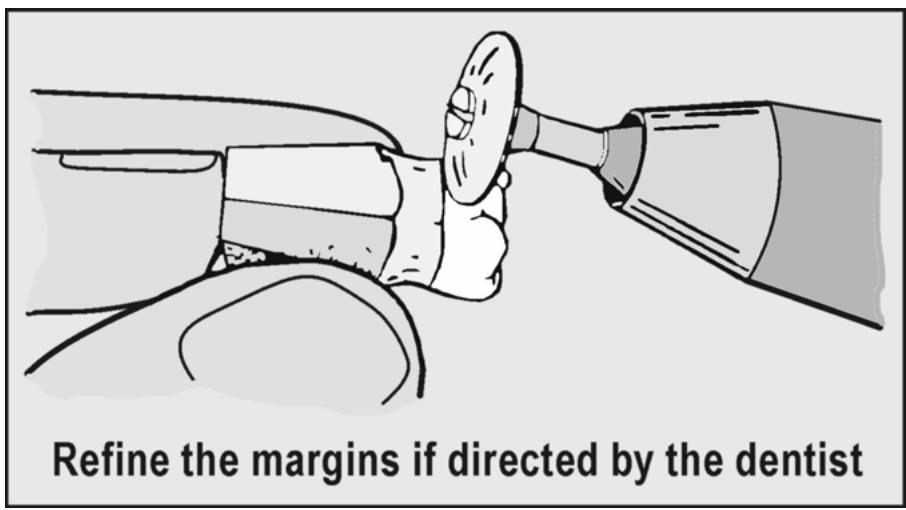
text_image
Refine the margins if directed by the dentist
1.58.7.2.3. If the casting is finished on the die, the die will probably be ruined. The dentist should be prepared to accept this.
1.58.7.2.4. Apply BBC and rouge to all external surfaces of the casting as the last steps in the polishing procedure. Clean offall polishing compounds with soap and water or by immersion in an ultrasonic cleaning device.
¶ Section 1L — FPDs (Retainers, Pontics, and Connectors)
¶ 1.59. Overview
1.59.1. An FPD is a replacement formissing natural teeth that is cemented to existing teeth in the patient’s mouth. Once cemented, an FPD cannot be removed without a great deal of difficulty.
1.59.2. An FPD is composed of two kinds of units, retainers and pontics, and the unit castings are jointed together by connectors (Figure 1.67)
Figure 1.67. Parts of an FPD.
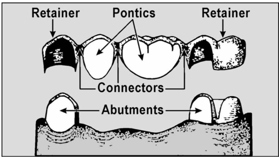
1.59.3. The dentist prepares (reduces the tooth st ructure) an adequate number of natural teeth adjacent to an edentu lous space to provide eno ugh support and retention for the FPD. The natural teeth the dentist prepares are abutments. Metal castings (on lays, complete crowns) are made to replace what the dentist reduces on the abutment teeth. These castings are retainers.
1.59.4. A pontic is an a rtificial tooth suspended from the retainer castings. A pontic occupies the space formerly occupied by a natural toothand is attached to a retainer by a connector.
1.59.5. Connectors can be rigidor nonrigid. There are two types of rigid connectors—solder joints and cast joints (multiple wax patterns joined with wax at their proximal surfaces and cast as one piece). Nonrigid connectors take the form of key and keyway interlocking parts (patrix and matrix interlocking parts, respectively).
¶ 1.60. FPD Designs
1.60.1. The typical FPD consists of one or more pontics rigidly suspended between tworetainers, one on each side of the edentulous space. Norm ally, an a butment at bothends will support an FPD, but there are special situat ions where this requirem ent is waived. When a pontic is suspended from only one retainer, it is cantilevered.
1.60.2. The best example of a cantilever FPD involves replacement of the maxillary lateral incisor, when the adjacent central incisor and canine are still present. In some cases, the dentist chooses to preserve the central incisor and does not prepare it as an abutment. The prosthesis will then consist of a canine retainer and a lateral incisor pont ic. The reasoning behind this compromise is that the maxillary canine is very strong and can bear ch ewing loads for itself and for a small, relativ ely nonfunctional lateral incisor pontic.
1.60.3. The dentist is obligated to prepare enough teeth to provide adequate support for an FPD, usually at least two. For long span FPDs (four units or more) or in cases where potential abutment teeth are somewhat mobile, the dentist might prepare more than two teeth as abutm ents. When a pontic is attached to two adjacent, join ted retainers, the prosthesis is s aid to have double abutments. It is possible to have double abutments on bothends of the prosthesis.
1.60.4. There are patterns of natural tooth loss where two edentulous spaces are separated by an intervening tooth, and at least one tooth remains distal to the posterior edentulous space (Figure 1.68). When an FPD is made to bridge the two edentulous spaces, the intervening tooth will be prepared as an abutm ent. On this kin dof FPD, the most mesial and the most distal abutments are called primary abutments and the intervening tooth is called an intermediate abutment or pier.
Figure 1.68. Intermediate Abutment.
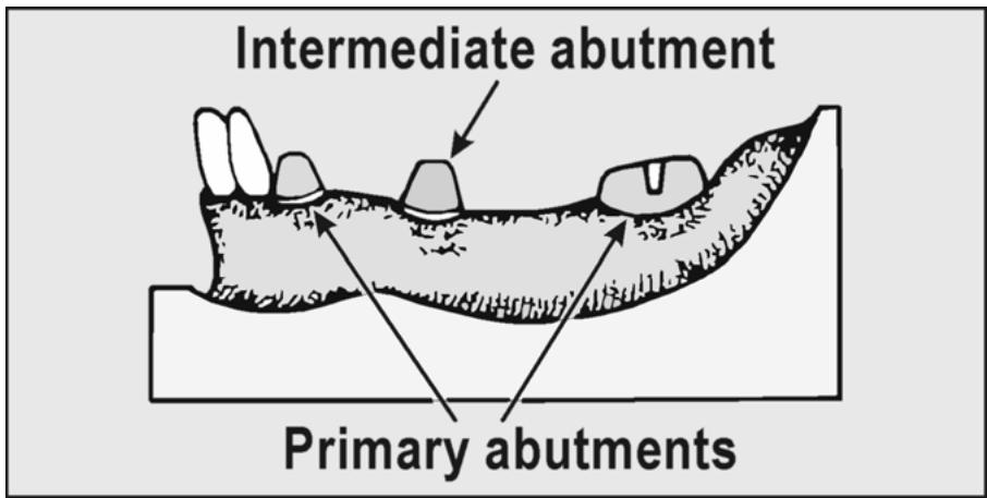
text_image
Intermediate abutment
Primary abutments
1.60.5. Rigid connection between all units of an FPD is recommended most of the time. However, a key to keyway, nonrigid connector, placed be tween one retainer and pontic, is an acceptable alteration in design for special situations.
1.60.6. For example, rigid connectors cannot be used between all units of a case where the dentis t is unable to prepare the abutment teeth with a path of insertion commonto all of the abutments. In another exa mple, maxillary FPDs with canine interm ediate abutm ents tend to bre ak loose from their abutments when all of the connectors are rigid. (This kindof pr osthesis “turns the corner” of the maxillary arch and the abutm ents are subje cted to unu sual stress es.) To “brea k” or redu ce stress, a dentist might decide to prescribe a nonrigid connector distal to the canine.
¶ 1.61. Steps in FPD Construction
For steps in FPD construction, see Figure 1.69 and as follows:
1.61.1. Make working casts with removable dies.
1.61.2. Mount the casts and trim the dies.
1.61.3. Wax the retainer and pontic patterns.
1.61.4. Sprue, invest, and cast the patterns.
1.61.5. Seat the casting, desprue, and solder the FPD, if necessary.
1.61.6. Satin finish the castings and adjust the occlusion.
1.61.7. Veneer the castings with applications of porcelain or acrylic resin, if prescribed.
1.61.8. Polish the completed restoration.
¶ 1.62. Materials Used in Making FPDs
The units of an FPD may be made entirely from metal, a combination of metal and acrylic resin, or a combination of metal and porcelain. To satisf y esthe tic requirements, use appropriate laboratory equipm ent to veneer retainers and pontics with porcelain fused to metal or with acrylic resin processed to metal.
¶ 1.63. Retainer Construction
The dentist determines the type of retainers needed and prepares abutment teeth accordingly. The most commonly used retainers are complete crowns, partial crowns, and onlays. Retainers, regardless of their finished composition, start out as wax patterns. The only exception is som e all-ceramic system s that do not use the lost wax techniqu e. Section 1I addresses construction of wax patterns for individual restorations. Use Section 1I to construct the retainers because the direc tions for retainer patterns are e ssentially the same as sing le u nit con struction. Basic patterns must be modified when retainers are programmed for acrylic resin or porcelain application. (See Chapter 2 of this volume for ceramic veneers and Chapter 5 of this volume for acrylic resin veneers.)
Figure 1.69. Fabricating a Posterior FPD.
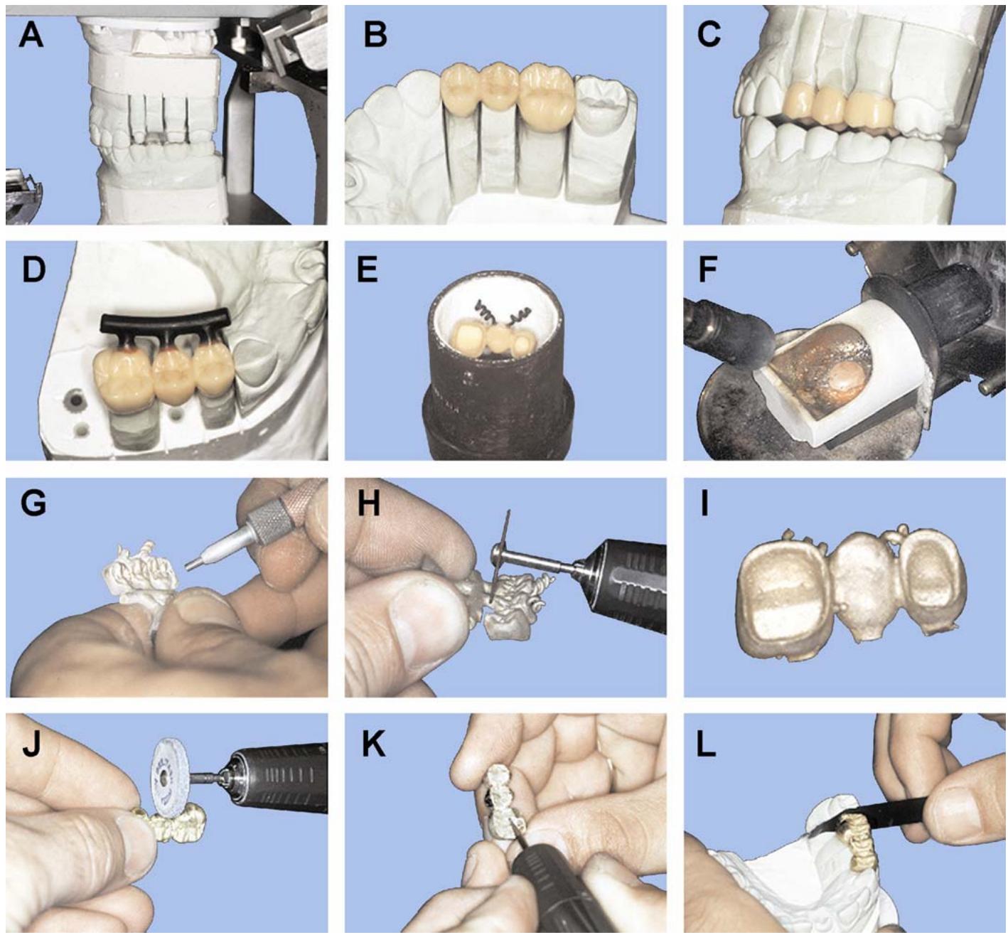
Figure 1.69. (Continued).
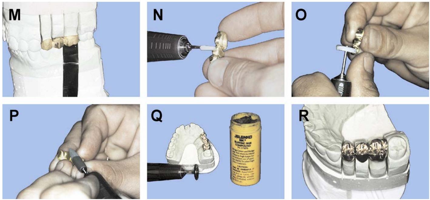
¶ 1.64. Pontic Designs
Although most of a typical pontic conforms to the shape of the tooth it is replacing, the linguogingival one-third to one-half has to deviate from a crown’s natural shape for hygienic reasons. A pontic that duplicates a crown’s natural shape exactly would lap over (saddle) the residual ridge from facial to lingual, and this kindof broad coverage is very unhealthy. It fosters food debris retention and gingival tissu e inflammation. As much as possi ble, construct pontics with rounded contours, avoiding sharp angles, whic h are harder to floss and prom ote debris retention. The following three types of pontic design are generally used:
1.64.1. Modified Ridgelap. The style of gingival adaptation most universally used is the modified ridgelap (Figure 1.70). The modified ridgelap closely resembles the shape of a natural tooth from the facial view. It is the shape of choice formaxillary anterior, maxillary posterior, and mandibular anterior pontics. It is also used formandibular posterior pontics when there is sufficient buccal sulcus depth. Contact with the residual ridgeshould extend no farther lingua lly than the crest of the ridge. (An ideal area of contact between a modified ridgelap pontic and the residual ridge is illustrated in Figure 1.71.)
Figure 1.70. Modified Ridgelap Pontic Forms.
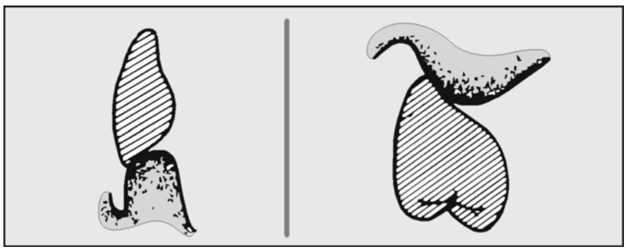
natural_image
Two abstract diagrams showing shaded regions on white background, no text or symbols present
Figure 1.71. Modified Ridgelap Pontic Gingival Contact Area.
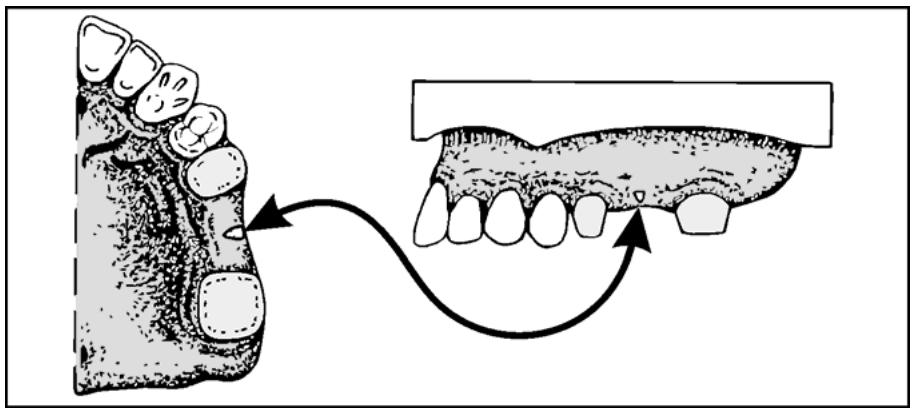
text_image
Diagram illustrating dental correction using a double-sided tooth model, showing tooth alignment and correction steps.
1.64.2. Conical (Figure 1.72)
If ridge resorption is slight to moderate and the buccal sulcus is shallow, the conical pontic is substituted for the modified ridgelap form. The concern is that a pontic with a facial lap might impinge on an active, shallow sulcus. The gingival half of the conical pontic is form ed into an “egg” shape, both mesiodistally and buc colingually with a ridge contact area localized to a small spot on the crest of the ridge.
Figure 1.72. Conical Pontic Design.
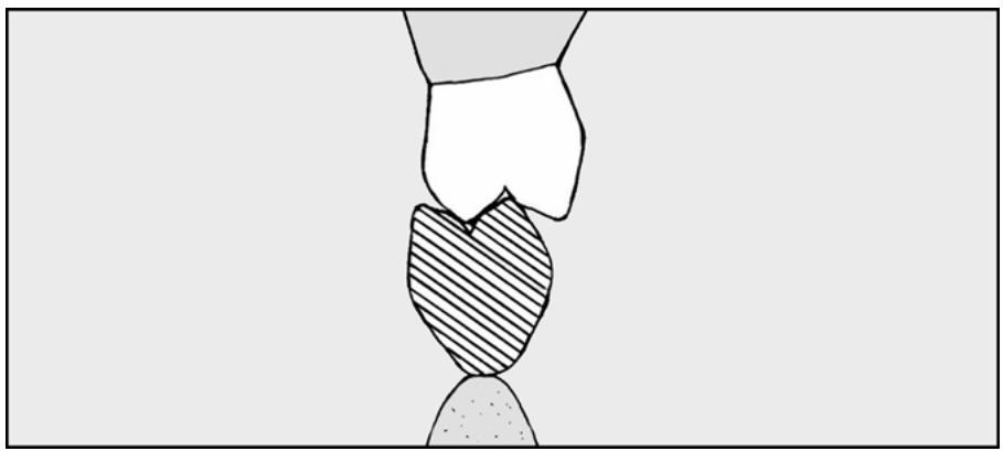
natural_image
Simple line drawing of a hand holding a shadedoval object (no text or symbols)
1.64.3. Hygienic (Figure 1.73)
When ridge resorption is very far advanced the hygienic pontic is used. The hygienic pontic has no contact with the ridge and is suspended a minimum of 2 mm (and not more than 4 mm) over the crest of the ridge. An alternative design of the hygienic pontic also appears in Figure 1.73 and is called the archway (modified) pontic. Proponents claim that because of this pontic’s shape, it is easier to clean and has more strength in the connector areas.
¶ 1.65. Pontic Construction (Figure 1.69)
As a general guideline, first fabricate the pontic ’s full axial and gingival contours in wax. Rigid (wax) connector areas may be formed at this time. (Connectors are discussed in depth in paragraph 1.68). Next, wax the occlusal surface and establish occlusal contacts. If the dentist p rescribes a veneered surface, modify the pattern for the veneered surface at this time. (See Chapter 2 of this volume for ceramic veneers and Ch apter 5 of this volum e for acr ylic resin veneers.) Use one of several pontic designs discussed in paragraph 1.64 while fabricating an FPD.
Figure 1.73. Hygienic Pontic Design.
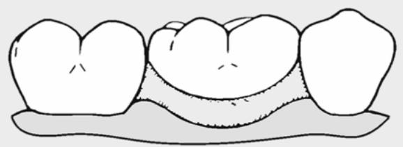
natural_image
Simple line drawing of three teeth on a base (no text or symbols)
CONVENTIONAL
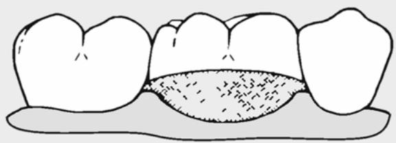
natural_image
Simple line drawing of three teeth with a shaded central cavity (no text or symbols)
MODIFIED
1.65.1. Overview. The facial and lingual shape of a pontic should imitate the corresponding contours of the natural tooth it is replacing as much as possible. The long axis alignment and faciolingual position of the pontic should fall within limits that are n ormal for the crown of a natural tooth. Besides looking good in the patien t’s mouth, a well form ed pontic positioned to harmonize with adjacent natural teeth will h elp maintain gingival health by shunting food properly.
1.65.2. Facial Surface (Figure 1.74)
1.65.2.1. One of the more important considerations affecting a pontic’s appearance is its facial surface length. Pontics that are too long or too short do not blend well with natural dentition. It is not enough to make a pontic just as long as the natural tooth it is replacing. For an observer to get an acceptable visual impression of facial surface length, the pontic’s cervical line as well as the f acio-occlusal or incisal edg e will have to fall in the right plac es rela tive to adjace nt teeth.
1.65.2.2. There are two methods of developing an acceptable visual impression of a pontic’s cervical position as ridge resorption increases. One is to make the gingival half of a facial surface more convex than usual. The other is to deviate from the normal long axis alignment by depressing the neck of the pontic. F requently, both of these methods are used at the same time. When ridge resorption is slight to moderate, depend more on depressing the neck than changing gingivofacial convexity to achieve the desired cerv ical line effect. If a ridge is substantially resorbed, there is little choi ce but to do both. Given that resorption is far advanced, a conventional FPD may not be indicated.
1.65.2.3. When possible, working and protrusi ve movement contacts should be borne by the natural teeth, not a pontic. This is one control over a pontic’s facio-occlusal or facio-incisal length. Another control is how the facial edge lines up with the remaining teeth. Extend the facial cusp ridges of a posterior pontic or the in cisal edge of an anterior pontic as far as these controls allow. Many frustrating situations will arise where a pont ic’s facio-occlusal or incisal edge is oriented at just the right level to look good in a patient’s mouth, but the pontic’s vertical overlap causes it to have contacts in working and protrusive excursions. Decreasing the vertical overlap or increas ing horizontal ov erlap will reduce or eliminate the force of the excursiv e contacts, but it also compromises the pontic’s appearance. It is up to the dentis t to give specific advice in these cases.
Figure 1.74. Positioning the Cervical Line of an Anterior Pontic.
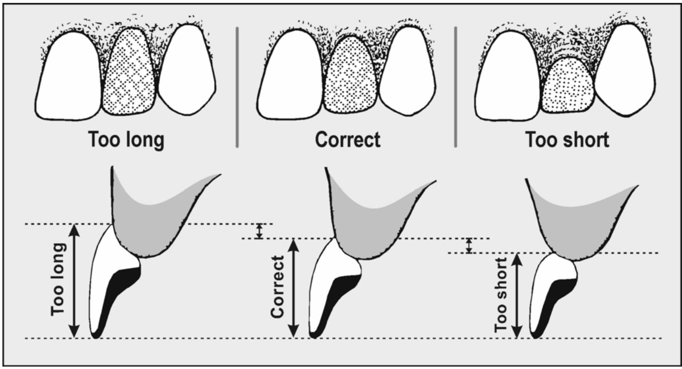
text_image
Too long
Correct
Too short
Too long
Correct
Too short
1.65.2.4. A pontic’s facial surface convexity as viewed from mesial to distal affects its appearance significantly (Figure 1.7 5)
When the mesiodistal width of an edentu lous space is greater than the toothxtracted from the spot, the facial aspect of an oversized pontic is shaped to produce a mesiodistally convex surface that scatters reflected light rays and gives the illusion of being a narrower pontic than it is. When teeth adjacent to a space have drifted to make the space narrower than the natural tooth was, the facial surface of the pontic is flattened toreflect more light straight back into the viewer’s eyes and create an illusion of a wider pontic.
Figure 1.75. Mesiodistal Convexity.
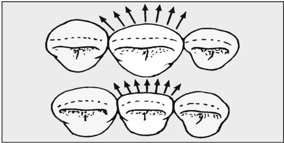
text_image
Diagram illustrating fluid flow around a central object with arrows indicating direction of velocity or pressure, labeled with numbers 1 to 17.
1.65.3. Lingual Surface.
1.65.3.1. Anterior Pontics. An anterior pontic’s lingual contours, down to the junction between its middle and gingival thir ds, should more or less imitate adjacent natural teeth. As a general rule, anterior pontics do not have worki ng and protrusive contact s; it is bette r tha t natural teeth bear such loading. This means vertical and horizontal overlap must be controlled, often to the detrim ent of the pontic’s appear ance. The lingual height of contour is roughly located at the junction of the pontic’s gingival and middle thirds. The lingual surface below the height of contour tapers intoward the crest of the ridge where initial contact with the ridge is made.
1.65.3.2. Posterior Pontics. The shape of the occlusal half of a posterior pontic’s lingual surface should conform to accepted food-sh unting standards for retainers. The height of contour is located at the junction between the pontic’s occlusal and gingival halves. The lingual surface below the height of contour tapers intow ard the crest of the ridge where initial contact with the ridge is made.
1.65.4. Proximal Surfaces. Mesiodistally, a pontic is constructed to fill the edentulous space. However, embrasures between pontic and retainer units of an FPD should be sufficiently open to allow effective cleaning. If the embrasures are too open, they become obvious to the casual observer and represent gross food traps.
¶ 1.66. Pontic Occlusion
Pontics must function or occlude against opposing teeth according to the same rules as individual cast restorations with one significant exception—pontics should clear opposing teeth in working and protrusive excursions no matter what kindof occlusion scheme is involved. The limit of acceptability in this regard is light contact. An extension of this principle is that no pontic should bear the burden of anterior guidance. To the extent possible, working and protrusive excursion contacts should be borne by well supported natural teeth. When not possible, consult the dentist.
¶ 1.67. Pontic Occlusal Surface Area
The occlusal surface area of pontics should be the same as or slightly narrower than the adjacent teeth. (Pontics should not be arbitrarily narrowed by a set percentage as was taught in the past.) A narrowed occlusal surface is sometimes compared to a malposed tooth that cannot shunt food properly. It is considered a poor practice, which results in soft tissue damage in the edentulous space. One method of checking the facial-lingual widthis to measure the corresponding natural teeth using a Boley gauge. Rem ember, the occlusal table width (buccal cusp tip to lingual cusp tip) represents just a fraction of the total buccal-lingual width of teeth (Figure 1.76). The mistake made most often is to unknowingly widen the occlusal table by placing the cusps too far apart.
Figure 1.76. Occlusal Table Width Compared to Overall Buccal-Lingual Width.
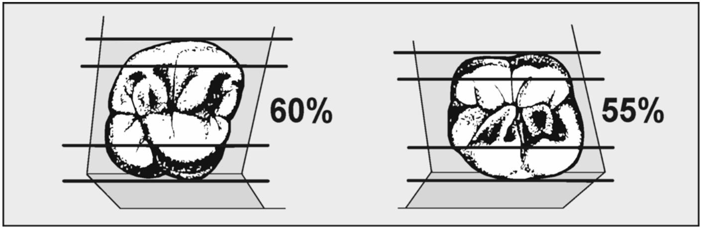
wireframe
| Panel | Percentage |
|---|---|
| Left | 60% |
| Right | 55% |
¶ 1.68. FPD Connectors
The various means used to join fixed prosthodontic units are single-piece casting, nonrigid (stress breaker) connectors, and soldering, as follows:
1.68.1. Single-Piece Casting (Figure 1.77)
1.68.1.1. One way to fabricate an FPD is to connect all units during the wax-up and cast it into a single piece. This method is widely used, but requires the technician to pay close attention to the fit of the wax-up on the stone dies prior to spruing and casting in order to achieve a solid fit (norocking) of the casting.
Figure 1.77. Single-Piece Casting of an FPD.
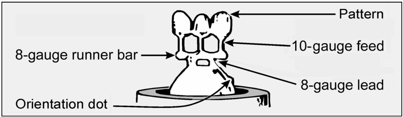
text_image
Pattern
10-gauge feed
8-gauge runner bar
8-gauge lead
Orientation dot
1.68.1.2. A single-piece die (see Figure 1.19) is very useful in achiev ing a so lid fit of the casting. A good guideline is to cast in two pieces and solder any FPD larger than three units. The accuracy of the casting declines as the number of units increases. As an exam ple, a fiveunit FPD can be cast as separate tw o and three-unit segm ents and late r joined by soldering. Note that the choice of materials for preparing multiple unit patterns can vary.
1.68.1.3. Wax patterns made by conventional t echniques with regular inlay wax work well. Patterns that are a combination of resin and wax are equally acceptable. When the patterns for individual units have been satisfactorily positioned on a working cast, join them together with a drop of inlay wax to form a multiple unit pattern. Contact areas are generally egg-shaped, with the long axis of the “egg” being oriented buccolingually.
1.68.1.4. Occlusogingivally, the contact area is located at the junction of the occlusal and middle thirds of a proximal surface. Buccolingually, the contact area can be found at the junction of the buccal and middle thirds of a posterior tooth’s proximal surface; except between the maxillary molars, where it is located near the occlu sal mesial/distal developmental groove area (Figure 1.41). The minimum width of a conn ector is 2 mm and the minimum depthis 2.5 mm. Use extreme care when working with the wax patterns to minimize distortion.
1.68.2. Semiprecision (Stress Breaker) Attachment.
1.68.2.1. A stress breaker is a mechanical type of connect or that depends on the dovetail retention principle to unite FPD units (Figure 1.78)
It consists of two interlocking parts, a key (or male) element and a keyway (or female) portion.
1.68.2.2. When used, the stress breaker connector usually joins the distal proximal surface of the anterior retainer to the mesial proximal surface of the adjacent pontic. The pontic carries the key, and the retainer houses the keyway. As far as relative dimensions are concerned, a keyway should be at least twice as deep, occlusogingivally as it is wide buccolingually. The key portion of a stress b reaker connector is not ordinarily made to fit the keyway with absolute precision. Limited buccolingual movement between the connector parts is desirable.
Figure 1.78. Semiprecision Attachment.

1.68.2.3. One of the major advantages of a broken stress connector is that an FPD can be made for a case where the abutm ent preparations are not parallel to each other or when an FPD includes a pier abutm ent. A serious disadvantage is that its use is restricted to short sp an segments replacing only one tooth.
1.68.2.4. Semiprecision attachments are comm ercially available in various sizes. An adequate stress breaker connector can be made from materials found in most dental facilities. The following paragraphs described two types of attachments:
1.68.2.4.1. Commercial Attachment (Ney Mini-Rest)
The Ney mini-rest has a slightly tapered, dovetail design. To help position this attachment, a surveyor mandrel is molded as an integral part of the key portion. The key and keyway parts are made of acrylic resin and are completely eliminated during burnout. Proc edures formaking FPDs with a Ney Mini-Rest are in Figure 1.78 and as follows:
1.68.2.4.1.1. Mount the casts (Figure 1.79- A)
Seat the key (male) portion of the attachment in the keyway (female) part (Figure 1.79-B). Determine the position of the mini-rest by placing the mandrel (on the key portion) in a surveyor and relating the attachment to the dies on the working cast. Although the keyway part of the attachment will probably be placed in the FPD’s anterior retainer, the key’s path of insertion into the keyway has to line up with the lon g axis or the distal abutm ent preparation. Mount the working cast on a surveying table and establish the attachment’s best orientation to the distal abutment die. Lock the survey table at the selected tilt (Figure 1.79-C).
1.68.2.4.1.2. Complete the wax patterns and carve a recess in the pattern destined to receive the keyway. While mounted on a surveyor, move the attachment into this recess and seal the keyway portion in position (Figure 1.79-D). Remove the mandrel-mounted key from the keyway and take the mandrel out of the surveyor’s spindle. The surveyor is no longer needed.
1.68.2.4.1.3. Cast the pattern that contains the keyway portion of the attachment. Satin finish the casting’s exterior surfaces and test fit it on the die (Figure 1.79-E). Adjust the proximal contact if necessary. Be certain the casting is fully seated on the die in the working cast (Figure 1.79-F).
1.68.2.4.1.4. Wax the pontic and distal retainer (Figure 1.79-G)
Carve enough wax away from the proximal surface of the adjacent pontic to accommodate the key part of the attachment. Align the pontic on the working cast in proper relation to the edentu lous ridge and opposing teeth. Seat the key portion of the attachment in the keyway and join the key to the pontic pattern (Figure 1.79-H). Cut the mandrel off the key with a hot
spatula (Figure 1.79-I) and sprue the patterns. Sprue and cast the distal retainer, pontic, and key in one piece (Figure 1.79-J).
Figure 1.79. Fabricating an FPD With a Semiprecision Attachment.
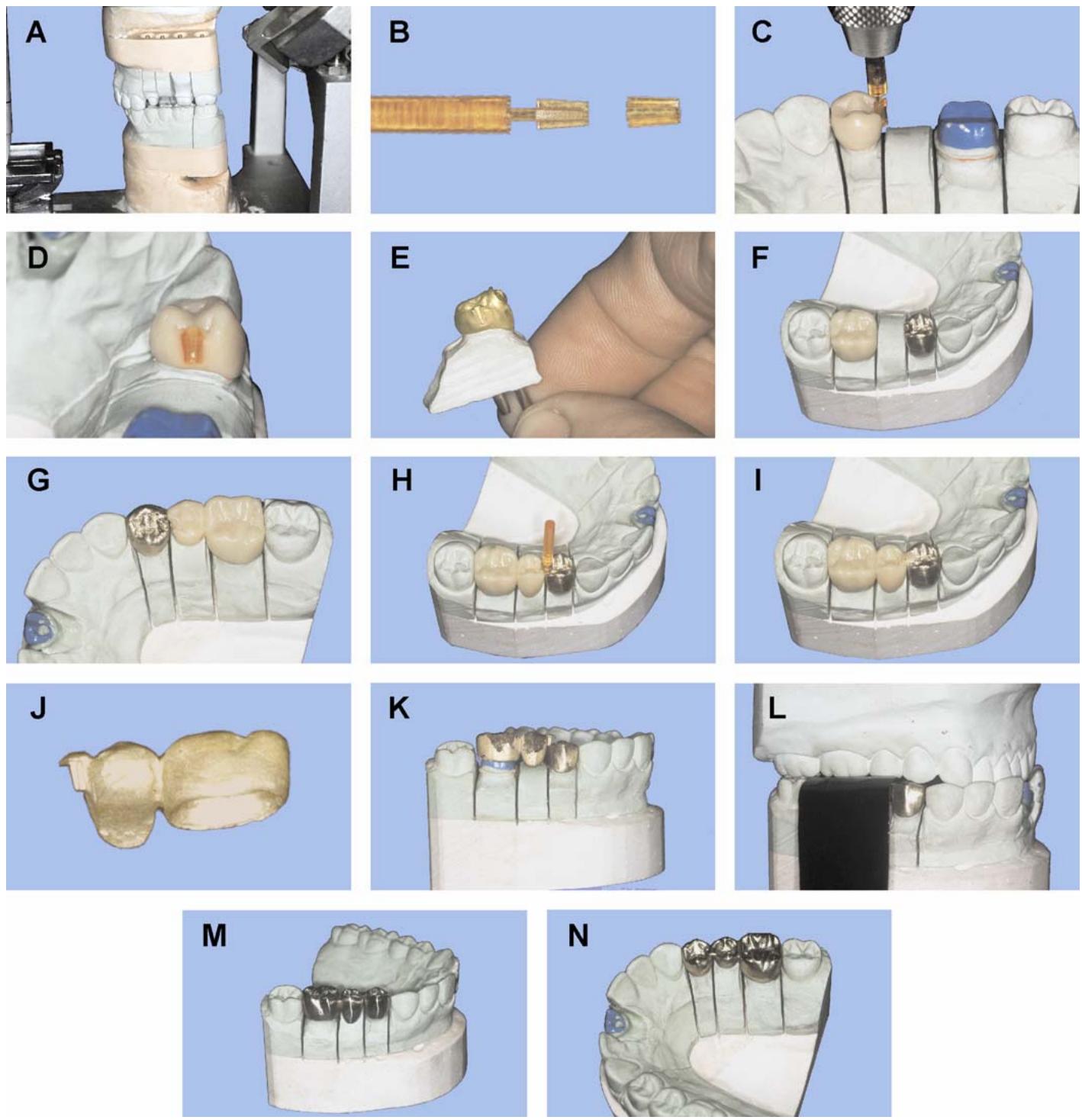
1.68.2.4.1.5. Finish, adjust, and polish the castings (Figure 1.79-K through -N)
The minirest does not provide for un limited movement between segm ents of the FPD, but it does allow normal tooth movement.
1.68.2.4.2. Technician-Fabricated Key and Keyway (Figure 1.80)
1.68.2.4.2.1. Flatten off one long edge of a wooden or plastic dent al matrix wedge and round the other two long edges slightly (Figur e 1.80-A)
Use cyanoacrylate glue to attach the flattened edge of the wedge to the smooth side of a plastic backing (Figure 1.80-B). Round off the junction between the wedge and the backing by applying a minimal amount of molten inlay wax to the two lines of union (Figure 1.80-C). Trim the backing and the pointed end of the wedge to provide a definite seat for the key in the keyway (Figure 1.80-D).
Figure 1.80. Technician-Fabricated Key and Keyway.
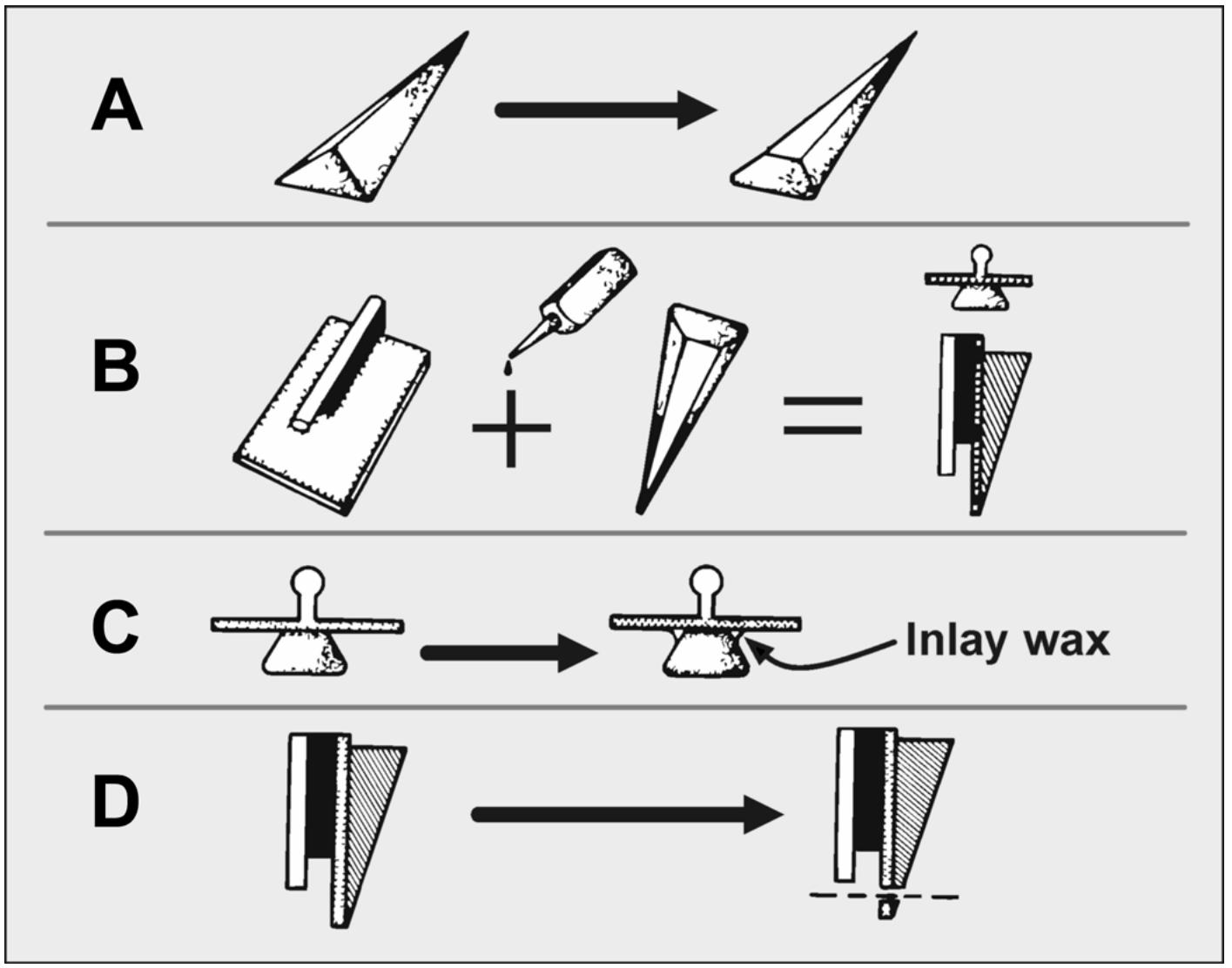
1.68.2.4.2.2. Make a rubber impression of the backing and wedge side of the assembly. Using the sprinkle-on technique, fill the impression with acrylic resinto form a plastic pattern. Many such patterns can readily be made from the same impression. Grinding can easily m odify the resultant keys if necessa ry. Use large patterns formolars and small patterns for premolars and anterior teeth.
1.68.2.4.2.3. Use sticky wax to mount the plastic pattern of the key on an analyzing rod. The long axis of the pattern should parallel the rod. Place the working cast on a surveying table and determine the best orientation of the dies to the key as previously described for the Ney mini-rest. Lock the table at the selected tilt.
1.68.2.4.2.4. Now that all patterns are completed, cut a recess into the retainer pattern destined to contain the keyway. The recess should be large enough to accommodate the plastic pattern of the key.
1.68.2.4.2.5. Lubricate the key. Place the working cast on the surv eying table and position the key in the retainer pattern’s recess. Flow melted inlay wax over the resin key and incorporate it into the contour of the retainer. Complete the key from the wax. Invest, cast, and finish the retainer, taking particular care to preserve the accuracy of the keyway.
1.68.2.4.2.6. Position the finished retainer on the die and replace the plastic pattern in the keyway. Make wax patterns for a one-piece casting of the posterior retainer and pontic, incorporating the key pattern into the pontic pattern. Sprue, invest, and complete the onepiece casting.
1.68.2.4.2.7. Finish, adjust, veneer, and polish the FPD.
1.68.3. Solder Connectors. A two-piece casting can also be used to construct an FPD. When using a solder connector, first completely wax the retainers and pontic in one piece as previously described in paragraphs 1.63 and 1.65. Cut through the connector area to be soldered, using a wax saw or sutur e silk. The pontic should remain attached to the smaller retainer. The wax-up is no w ready to be completed and cast. After casting, the FPD can be soldered. Procedures for the soldering process are detailed in paragraph 1.75.
¶ 1.69. Completing the Wax-Up
Figure 1.81 and the following procedures apply to this process:
Figure 1.81. Refine the Margins and Smooth the Wax Patterns.
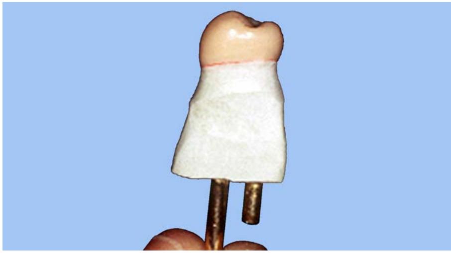
natural_image
Close-up of a dental model with toothd upper and metallic pins against a blue background (no text or symbols visible)
1.69.1. Refine the margins. When carving the junc tion between the wax and the stone die back to where the preparation b egins, use b lunt carv ers in steadof sharpinstrum ents. Blunt carve rs will produce a clean, well-defined margin without marring the die’s surface. NOTE: If the wax pattern margins are grossly distorted, remove the pattern and ca refully cut it b ack 2 mm off the margin. Apply a fresh coat of die lubricate to the die and reseat the pattern. Quickly flow molten wax into the space created to cover the margin and provide a smooth internal adaptation.
1.69.2. Sm oothand polish the patterns. Use the sof t br istle b rush to get at oc clusal surface irregularities. Use a piece of silk or nylon cloth wrapped around the end of a finger to smooth axial surfaces.
¶ 1.70. Spruing
1.70.1. Attach a 10-gauge wax sprue former (pattern sprue) to each unit as if it were an individual pattern (Figure 1.82)
Reduce the sprue formers to a uniform height of 4 to 6 mm from the patterns. Place an 8-gauge wax rod (runner bar) over them and seal them with molten wax. Depending on the number of units being cast, attach two or three 8- to 10-gauge wax sprue formers (lead sprues) opposite the pattern sprue formers on the runner bar.
Figure 1.82. Spruing an FPD.
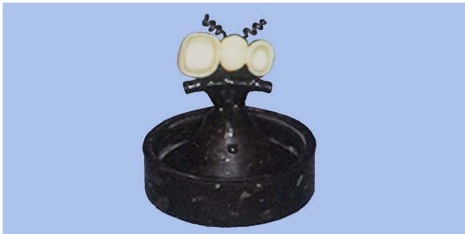
natural_image
Black ceramic object with three white spherical objects on top, resembling a stylized animal or abstract design (no text or symbols visible)
1.70.2. The lead and pattern sprue formers should be on the same plane, but not in direct line with one another. Cut off the lead sprue formers to a length tha t will position the patterns outside the thermal zone. Normally, this position places the pattern 6 mm from the end of the casting ring. Be sure to leave at least 6 mm of investment covering the pattern for strength.
1.70.3. Remove the sprued wax pattern from the working cast by carefully withdrawing it parallel to the long axes of the dies. Att ach the lead sprue formers to the sprue base at a common point of attachment. Use the wax orientation dot method torecord the position of the pattern in the r ing (paragraph 1.52.4.5). Indirect spruing is described in detail in paragraph 1.52.4.3.
¶ 1.71. Investing
Invest the pattern according to an acceptable method of choice. (See Figure 1.57 and paragraph 1.54.4.)
¶ 1.72. Burnout
Follow burnout procedures described in paragraph 1.55.
¶ 1.73. Casting
Use the reference dot on the investment’s crucible surface to precisely position the ring in the casting machine. If a horizontal casting machine is used, orient the pattern vertically with the pattern’s thin areas trailing while the machine is spinning. For additiona l guidance on casting see paragraph 1.56.
¶ 1.74. Finishing the FPD
Finishing an FPD is essentially the same as finishing a single unit (Figure 1.65). Additional care must be taken not to reduce the size of the connectors. A detailed description of the finishing process is given in paragraph 1.58.
¶ 1.75. Soldering
Soldering consists of applying heat to pieces of metal that are next to each other, flowing a lower fusing metal (solder) onto the surfaces of the adjoining pieces, and filling the intervening space at the same time. After the solder cools, the metal pieces are rigidly connected.
1.75.1. Requirements of a Solder Connector.
1.75.1.1. A solder joint has to be free of oxide and voids for maximum strength. Dental gold alloys contain base metals, particularly copper, that readily oxidize in the presence of oxygen. Satisfactory union between units will not take place unless the surfaces to be soldered are free from debris andoxide. Besides mechanical cleaning of the parts to be joined, a good soldering flux is essential.
1.75.1.2. The physiologic and mechanical success of the soldered connection also depends on the design or shape of the connection. The solder joint must be centered on the proximal contact area, triangular in shape with rounded corners, and have concave peripheral borders (Figure 1.83). The gingivo-occlusal or incisal length of the conn ection is critical. The soldered area must not encroach on the interdental tissue or allow a food pocket to be created (Figure 1.84). The joint has to be wide enough, faciolingually, for strength, but not so wide as to be visible and unsightly (Figure 1.83).
1.75.1.3. A solder joint has to unite the units of an FPD or splint precisely.
Figure 1.83. Solder Joint Between Two Posterior Castings (Proximal View).
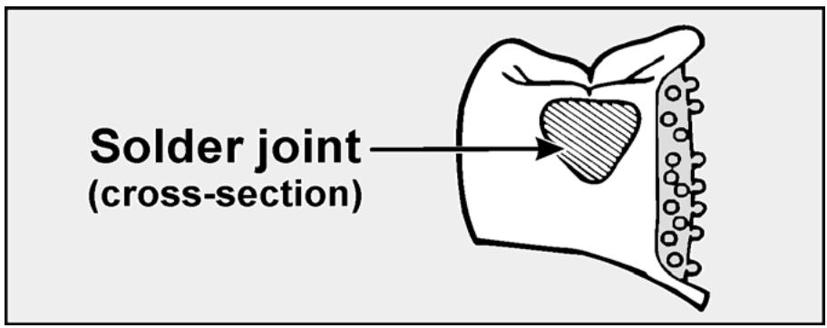
text_image
Solder joint
(cross-section)
Figure 1.84. Solder Joint Between Two Posterior Castings (Buccal View).
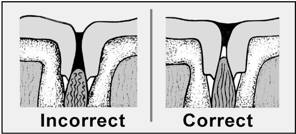
text_image
Incorrect
Correct
1.75.2. Procedures Associated With Soldering Type III Golds. (NOTE: Procedures for soldering porcelain fused to metal systems are in Chapter 2 of this volume.)
1.75.2.1. Aligning the Units on the Working Cast and Evaluating the Width of the Solder Gaps (Figure 1.85)
1.75.2.1.1. Remove all oxide from the proximal surfaces to be joined with a rubber wheel. Do not polish the surfaces. The solder bond is stronger on a satin finish.
Figure 1.85. Testing the Width of the Solder Gap.
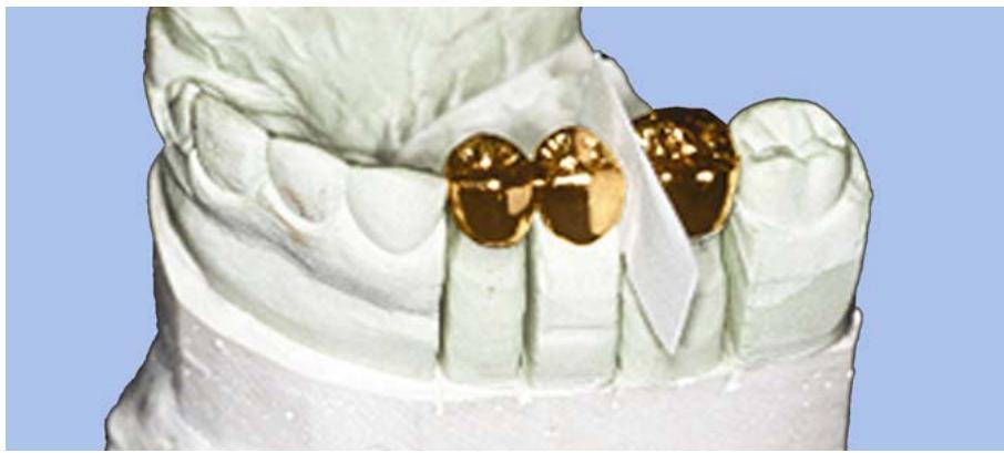
natural_image
Close-up of a dental model with gold crowns and a white tool, no visible text or symbols
1.75.2.1.2. Place the retainers and pontics on the cast. Seat the retainers on the dies as solidly as possible.
1.75.2.1.3. When assembling the FPD or fixed splint on the cast before soldering, the proper width of the solder gap between units is a very important consideration. Factors tha t affect the width of the solder gap are the setting expansion of the soldering investment, the thermal expansion of the investment, and the thermal expansion of the metal units.
1.75.2.1.4. The setting and thermal expansions of the soldering investment tend to increase the solder gap over what has been established on the cast. On the other hand, thermal expansions of the gold parts tend to close the gap. When the investment and metal units are heated, the overall effect is to close the solder gap. The width of the solder gap at its closes t pointshould be about 0.15 to 0.30 mm (0.005 to 0.010 inch). This distance, represented by two to three thicknesses of letter paper, may be judged by slipping letter paper through the gap while the units are assembled on the cast.
1.75.2.1.5. If the gap is too small, metal-to-metal contact of the units might occur during heating. Such contact could cause shifting of the units, warping of the metal, and possibly cracking of the investment. On the other hand, if the gap is too wide, the solder joint will be porous and the likelihood for distortion will be greater.
1.75.2.2. Relating Units to Each Other and Investing the Assembly. Units can be related to each other for soldering in either of two ways, the stone index methodor the resin method, as follows:
1.75.2.2.1. Stone Index Method (Figure 1.86)
The purpose of a stone index is to hold the castings in position while the solder investment is being poured:
1.75.2.2.1.1. First, paint a separating medium for dental stone onto the surfaces of the teeth adjacent to the fixed prosthesis. To form an index for a posterior FPD or splint, fill a segment of a used metal denture tooth card with low-expansion stone and place it over the occlusal surfaces of the castings (Figure 1.86-A). Include about half a stone tooth on each side of the prosthesis. The section of denture tooth card acts as a tray. Make a soldering index for an anterior FPD or splint on the lingual aspect of the arch. Cut and bend the denture tooth card to conform to the curvature or make a carrier out of baseplate wax.
Figure 1.86. Stone Index Method of Fabricating a Solder Investment Patty.
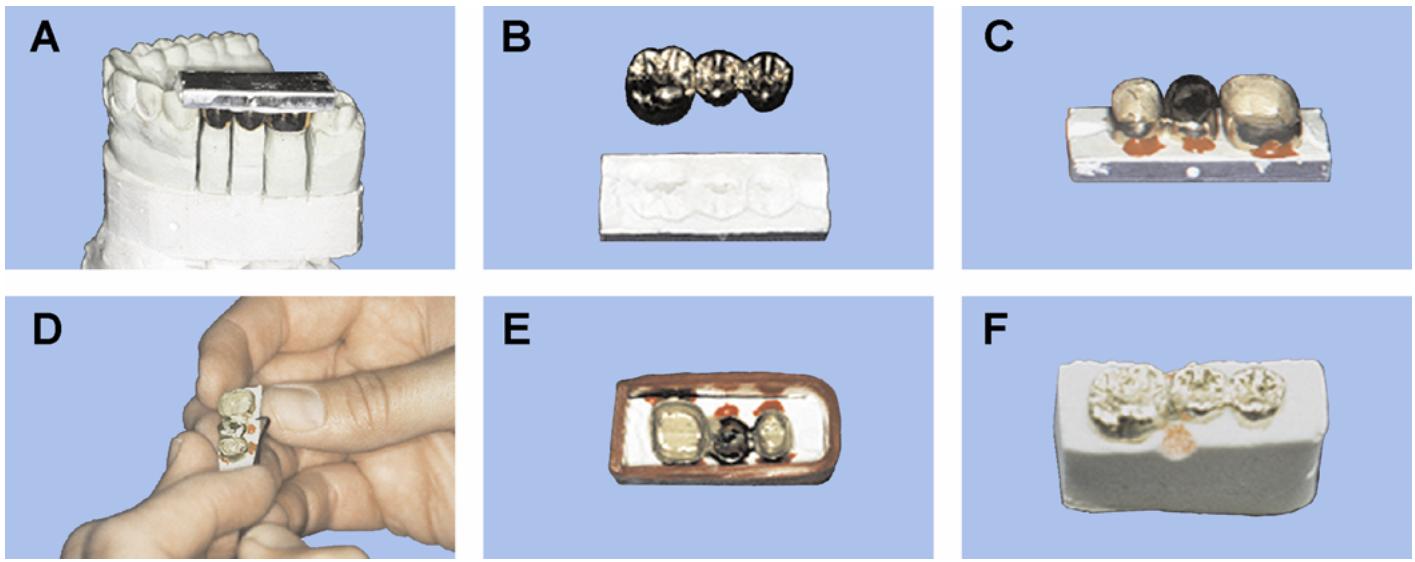
1.75.2.2.1.2. After the stone has set, remove the index. The index should include the cusp tips of posterior castings or the entire lingua l surfaces of anteriors. Anything more is unnecessary and should be trimmed away. Trim the index to 3 mm (1/8 inch) around the perimeter of the castings (Figure 1.86-B).
1.75.2.2.1.3. Remove the retainer castings from their dies. Reposition the castings in the index. Lute the castings in position by apply ing sticky wax (Figure 1.86-C). Do not use sticky wax in the join t areas because the wax contraction during cooling might make the castings move out of position.
1.75.2.2.1.4. Fill the embrasures in the joint areas with inlay wax. Carve the precise shapes of the solder connectors into the wax. This prevents solder investment from entering the solder joint gap (Figure 1.86-D).
1.75.2.2.1.5. Paint the exposed stone surfaces of the index with a separating medium.
1.75.2.2.1.6. Wrap a 15 to 20 mm wide strip of boxing wax around the index to form the solder investment patty (Figure 1.86-E)
1.75.2.2.1.7. Mix the solder investment according to the manufacturer’s instructions and paint it onto and around the castings with a soft brush. Fill the boxed index with investment material.
1.75.2.2.1.8. When the investment has set, separate the assembly from the index by immersing the assembly in boiling water, melting the sticky wax. Trim the investment to 15 to 20 mm thick and 3 mm (1/8 inch) around the perimeter.
1.75.2.2.1.9. Thoroughly flush away all wax residues from the investment with boiling water. Cut V-shaped channels leading from the edge of the investment to the metal parts to be soldered (Figure 1.86-F). These channels give the soldering flame access to the joint. Ensure no loose investment particles remain in the spaces between the units.
1.75.2.2.1.10. While the assembly is still warm from boiling, use an explorer dipped in flux to place a small amount of soldering flux onto the metal areas to be joined. (CAUTION: An excess of flux will cause pits and weaken solder joints.) The flow of solder has to be controlled. It cannot be allowed toruin margins or run onto carved. occlusal surfaces. Areas on which solder is not wanted may be covered with an antiflux, applied after the soldering flux application. A good antiflux is made by moistening rouge with chloroform and painting it on the areas wh ere solder is not desired. Use a small, soft brush to sparingly apply this mixture.
1.75.2.2.2. Resin Method (Figure 1.87)
Use a high-quality, fast-setting material such as Dura Lay® or Zap-It® to unite the castings. Ensure the castings are seated properly on the stone dies. Apply resin, using the brush-on technique or tube type dispenser into the solder joint area. Continue to do this until the resin has enough strength to allow handling of the prosthesis during subsequent steps. Once the resin has set and the prosthesis removed from the cast, check the tissue side of the joint for voids. If voids are present, add more resin. (Let the resin polymerize while the prosthesis is seated on the working cast.)
Figure 1.87. Resin Method.
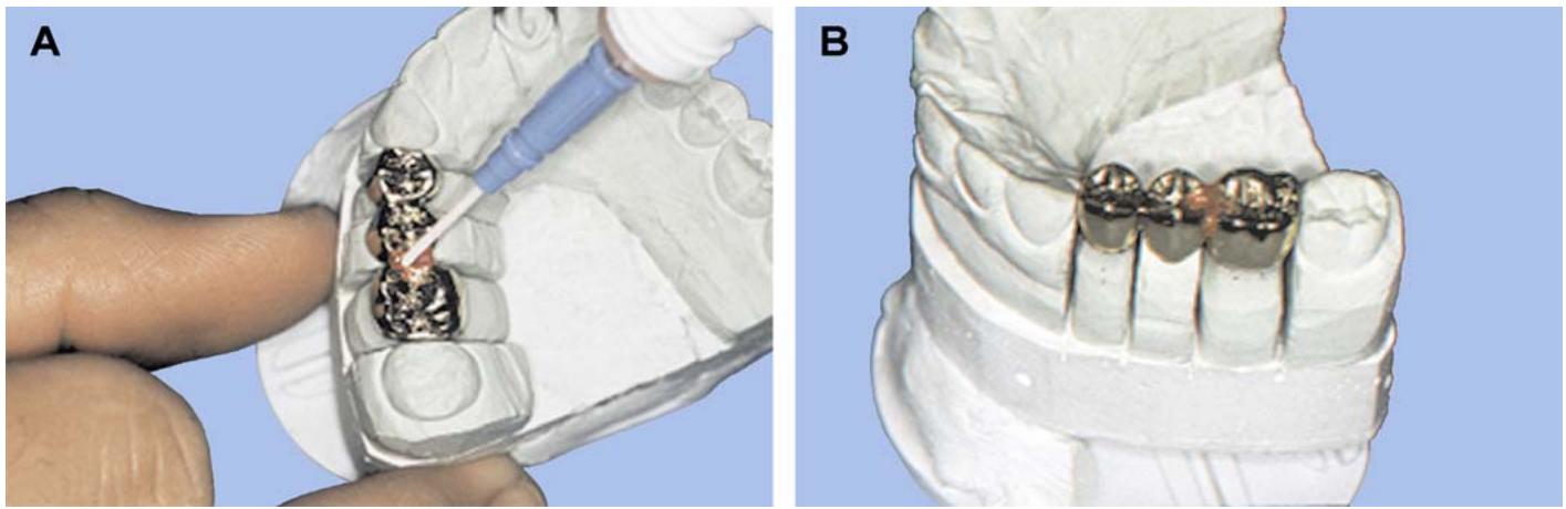
1.75.2.2.2.1. Place properly measured and mixed investment on a suitable work surface and build up to a height of 25 mm (1 inch)
Use small increments of investments to fill the inside of individual castings. Float the prosthesis on the moundof investment material. Stand the assembly upright and take care not to bury it. Le ave as much metal exposed as possible, but be sure that the margins are covered. Maintain a sufficient bulk of investment beneath the castings (15 to 20 mm) to provide strength during the soldering operation.
1.75.2.2.2.2. After the investment has set, trim it to these following dimensions. 15 to 20 mm thick and 3 mm be yond the perim eter of the castings. Cut a V-shaped groove from the edge of the investment to the joint areas. Paint around the periphery ofall joints with antiflux if desirable (paragraph 1.75.2.2.1.10).
1.75.2.2.2.3. It is not necessary to go through the boilout procedure associated with the stone index method. All of the resin will vaporize during the preheating operation in the burnout oven.
1.75.2.3. Secondary Laboratory Solder Relationship Index (Figure 1.88)
If a resin index has come directly from the patient’s mouth, it is a good idea to fabricate a secondary laboratory index to check the prosthesis for accuracy after soldering has been completed as follows:
Figure 1.88. Secondary Laboratory Solder Relationship Index.
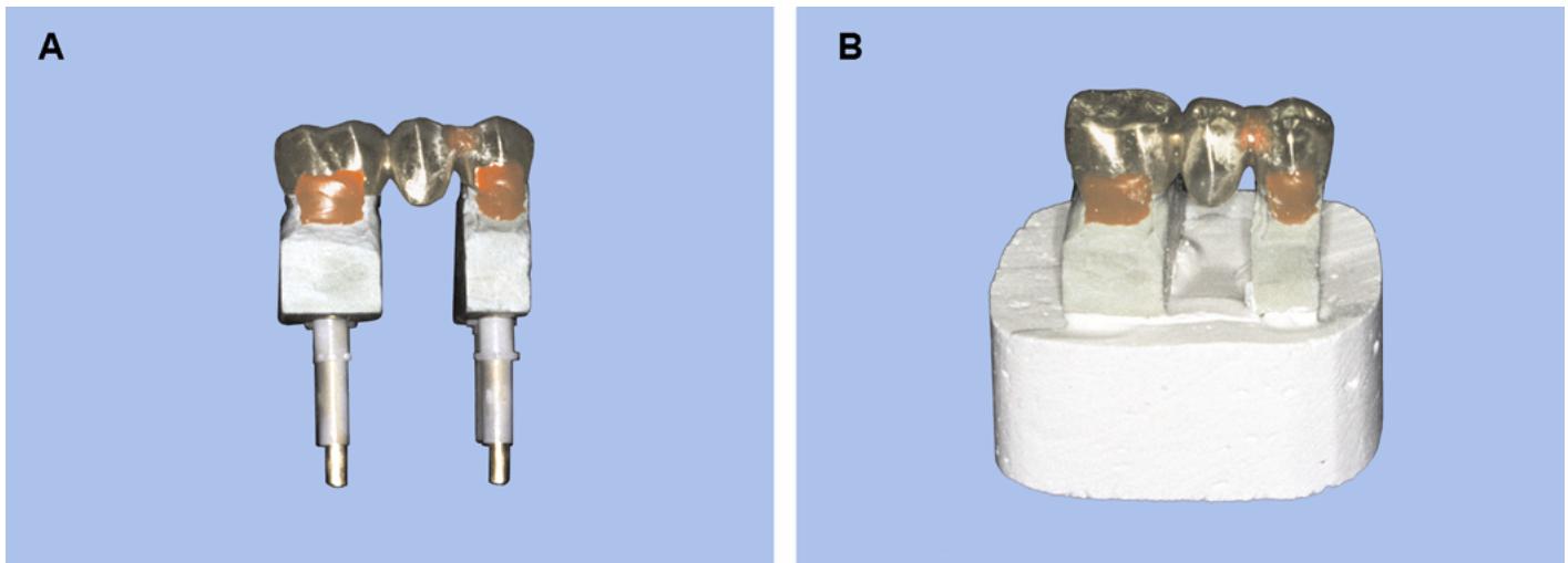
1.75.2.3.1. First, place the stone dies from the working cast into the castings and use sticky wax to hold them in place (Figure 1.88-A)
1.75.2.3.2. If pindex pins were used, slide new sleeves over the die pins. Mix the stone and place a moundon the bench thicker than the length of the lon ger die pin s. Gently place the dies with castings into the stone until the pins are fully covered. Do not bury the dies into the stone.
1.75.2.3.3. After the stone has set trim the stone patty leaving a 3 to 5 mm border around the perimeter of the dies (Figure 1.88-B)
1.75.2.3.4. Remove the castings and complete the soldering procedures. After soldering, return the FPD to the dies on the stone index and check for accuracy.
1.75.2.4. Selecting a Solder and Cutting the Strip Into Pieces. Select solder with a melting range at least 100 F below the melting range of the castings. The solder’s color must match the castings. There are two ways of getting solder to a joint area during the soldering procedure:
1.75.2.4.1. Feed the strip of solder into a cherry-red embrasure until a joint of satisfactory size develops.
1.75.2.4.2. Place a piece of solder of suitable size in the embrasure before the soldering. In the strip feed method, solder flow is fast and heavy and its spread is sometimes difficult to control even with antiflux. Solder may run onto delicate margins or onto occlusal surfaces to destroy carefully establishedocclusal relations hips. The size and shape of the joint can better be controled when the solder has been cut into pieces and pl aced with appropria te forceps.
1.75.2.5. Preheating the Assembly. Place the invested castings in a burnout furnace. Heat soak the assembly at 900 F for 30 minutes. Do not preheat the assembly over a bunsen burner flame. Because the part of the investment closest to the flame expands more rapidly than portions further removed, this causes distorted assembly relationships and occasion al investment cracking.
1.75.2.6. Soldering.
1.75.2.6.1. Adjust the torch flame so the reducing part of the flame is large enough to cover the connector area being soldered, but no la rger. The reducing atmosphere prevents troublesome oxide formation. A larger flame only increases the chances of releasing sulfur contaminants from the surrounding investment.
1.75.2.6.2. Remove the preheated assembly from the burnout oven and place it on a hot soldering frame. If not previously done, place a small amount of flux in the joint area. Coat a small square of solder with flux and place it in the linguo-occlusal embrasure of the joint area (Figure 1.89).
1.75.2.6.3. Using the reducing part of the flame, gradually heat up the units adjacent to the joint area. Avoid applying the heat of the torc h directly to the solder. When the castings become dull red in color, they are approaching soldering temperature. Switch from gradual heating of a relatively large area to concentrating the flame’s movement around the connector site. The units will become bright red, and the solder should flow. As soon as the solder flows, remove the flame.
1.75.2.7. Bench Cooling and Removing the Investment. Allow the soldered assembly to bench cool completely. Rapid quenching from a high temperature induces distortion. Slow cooling heat hardens the restoration. Cleanse the soldered castings of investment particles and pickle them to remove oxides.
1.75.2.8. Finishing. Proper control of the amount of solder used to make the connection will minimize the effort needed to finish the soldered area. Use a separating disc or a small tapered fissure bur (#669 or #700) to develop the final sh ape of the joint. A knife-edged rubber wheel will further smooth the area. Use guidelines for finishing in paragraph 1.58 for completion and polishing.
Figure 1.89. Soldering an FPD.
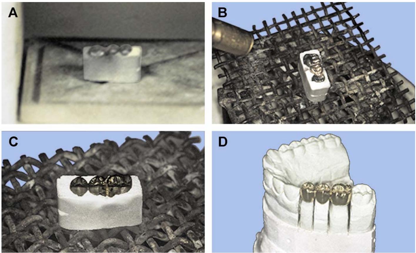
¶ 1.76. Repairing Metal Castings
1.76.1. Adding Proximal Contacts (Figure 1.90)
Normally, restorations have proximal contacts with adjacent teeth. When this contact is removed, it must be restored and the pro ximal surface must be recontoured. A dding a proximal contact to a single crown can be donewith or without first investing the case, while FPD castings must be invested. The freehand method is by far the fastest and easiest way. But, for those cases that must be invested, be sure to place the restoration in the inves tment patty so the area to be repaired is acces sible and in a horizontal plane. Let gravity work for you. Also, invested cases must be preheated in a furnace as described in paragraph 1.75.2.5. The following procedures describe the freehand method of soldering:
1.76.1.1. As always, rubber smooth the surface to be soldered. Outline the boundaries of solder flow with an antiflux such as a graphite pencil.
1.76.1.2. Pick up the crown with a pair of locking tweezers, hemostats, or cotton pliers. Make sure you don’t accidentally damage the margin. NOTE: To make a pair of soldering tweezers, bendone tip of a pair of locking tweezers. Place the bent tip on the inside of the crown to avoid crimping the margin.
1.76.1.3. Select the solder and cut a piece larger than actually needed. (The added bulk will help in recontouring the proximal surface.)
1.76.1.4. Warm the casting slightly over a bunsen burner flame and apply flux on the surface to keep oxides from forming. Dip the piece of solder into the flux and place it on the crown (Figure 1.90-A).
1.76.1.5. Place the casting in the reducing zone of the flame and keep it there until the casting glows a bright red. The solder should soon melt and adapt itself to the surface. Deoxidize the casting and finish it to proper contour (Figure 1.90-B).
Figure 1.90. Adding a Proximal Contact.
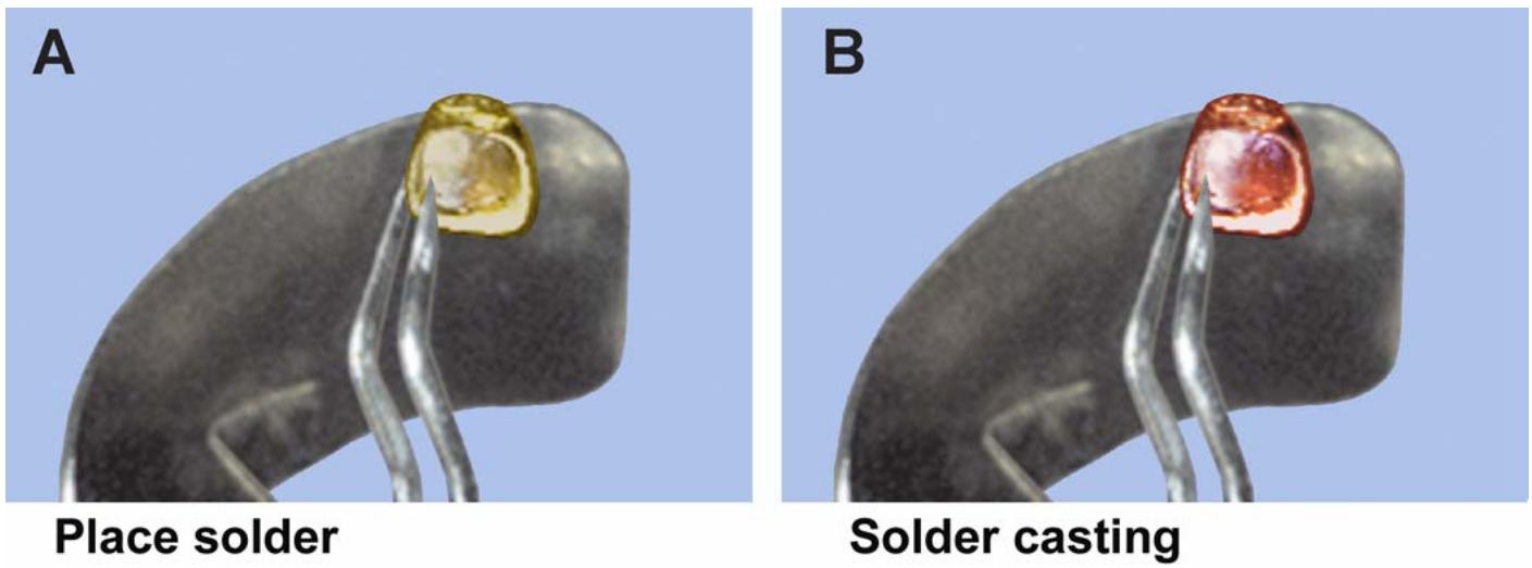
1.76.2. Repairing Casting Voids (Figure 1.91)
Some casting defects can be repaired by soldering, but not all. Small voids such as pits can be soldered freehand. Larger voids that extend all the way through a casting must first be invested. Also, a backing of platinum foil is used underneath the hole to aid in solder flow. Ho les on the o cclusal surface can be successfully repaired, but you risk covering the entire surface with solder. Do not try torepair deficient margins because it is improbable that adding solder will result in an acceptable margin.
1.76.2.1. Start by adapting a small piece of platinum foil onto the die and in the area under the hole. Seat the casting on the die and sticky wax the foil to the casting through the hole (Figure 1.91-A). Remove the casting and check to see that the foil stays in place inside the casting. Fill the casting with solder investment and set it down in a small investment patty.
Figure 1.91. Repairing Casting Voids.
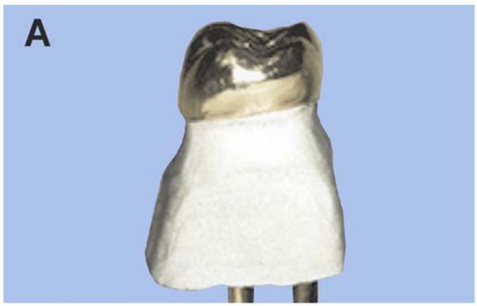
natural_image
Close-up of a dental implant or seal with a metallic base and toothd upper surface, labeled 'A' in the corner (no other text or symbols visible)
Sticky wax foil to casting
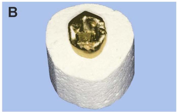
natural_image
Close-up of a white cylindrical object with a golden, irregularly shaped metallic object embedded in the center (no text or symbols visible)
Invested casting with solder and flux
1.76.2.2. After the investment has set, remove the sticky wax. Outline the area to be soldered with a graphite pencil. Apply a small amount of flux to the hole and preheat the assembly in a furnace at 900 °F for 30 minutes.
1.76.2.3. Remove the preheated assembly and position it on a soldering frame. Place a square of solder (slightly larger than the hole) over the hole (Figure 1.91-B) or touch a strip of solder to the casting as the soldering pro cedure nears completion. Heat the casting with the reducing zone of a gas or air torch. Do not direct the flame onto the solder. When the solder flows, remove the torch.
1.76.2.4. Divest the casting. Remove the platinum foil from inside by grinding it away with a small round bur. Finish and polish the casting in the usual manner.
¶ Section 1M — Remounting Casts With Low-Fusing Metal
¶ 1.77. Overview
1.77.1. Most times, the technician’s adjusting of the occlusion of a fixed prosthesis in an articulator b efore try-in and the dentist’s ref ining of the occlusion in the patient’s mouth are enough to ensure the prosthesis will function satisf actorily. However, the truth of this statem ent decreases as the number of units being placed in the patient’s mouthat one time increases.
1.77.2. In a situation where a complete mouth rehabilitation is being done and many units have been made for both arches, most dentists will order a remount ofall castings in the articulator after try-in. To do this, the dentist must try the castings in the patient’s mouth and make sure they fit the preparations, perform gross occlusal adjustments on the castings, seat all of the castings on the preparations and make maxillary and mandibular pickup impressions; make a new facebow transfer, and make a new jaw relationship record. Given the pickup impressions, castings, a facebow transfer, and a jaw relationship record, pour the impressions and remount the castings.
¶ 1.78. Remount Procedures
1.78.1. Prepare the pickup impression. The pickup impression usually consists of a combination acrylic resin and zinc oxide-eugenol matrix embedded in an alginate impression. Paint the interior of the casting with a white, liquid shoe polish and let the film dry. Position the castings in the impression, seating each casting firm ly and positively in the matrix. Protec t the margins of the castings by flowing a thin layer of rubber base impression material onto them.
1.78.2. Pour the pickup impression. Melt the low-fusing metal of choice as suggested in Volume 1, Chapter 2. Syringe the melted metal into the castings. Add enough additional metal to create an arch form at least 6 mm thick. After the metal cools, incorporate some form of mechanical retention into its base. For exam ple, heat paper clip loops or small brass screws and partially embed them in a number of places. Pour the rest of the impression in dental stone. Be sure to form a few retention nodules on the base of the stone.
1.78.3. Use the facebow transfer to mount the maxillary cast (paragraph 1.29.2)
1.78.4. Use the interocclusal jaw relationship record to mount the lower cast (paragraph 1.30.2)
1.78.5. Adjust the occlusion (paragraph 1.58.6)
1.78.6. Final polish as directed by the dentist. In complete mouth rehabilitation cases, this will probably mean applying a mandrel-mounted wire brush to the occlusal surfaces of posterior teeth and high shining the lingual surfaces and incisal edges of anterior teeth with jeweler’s rouge.
¶ Section 1N — Post and Core Castings
¶ 1.79. Construction Procedures
Most teeth that have been endodontically treated have been so destroyed by caries or previous restorations that there is very little clinical crown left. Often, only the root portion is left to retain the crown. A casting, called a post and core, must then be constructed for retention. This device anchors in the root and replaces the supragingival axial walls similar to the standard crown preparation. Post and core castings are most often associated with endodontically treated anterior teeth, but they may be used on posterior teeth as well (Figure 1.92). Patterns for post and core construction can be made of wax, self-curing acrylic, or metal and acrylic, using either the direct technique or indirect technique.
Figure 1.92. Post and Core Castings for Anterior and Posterior Teeth.
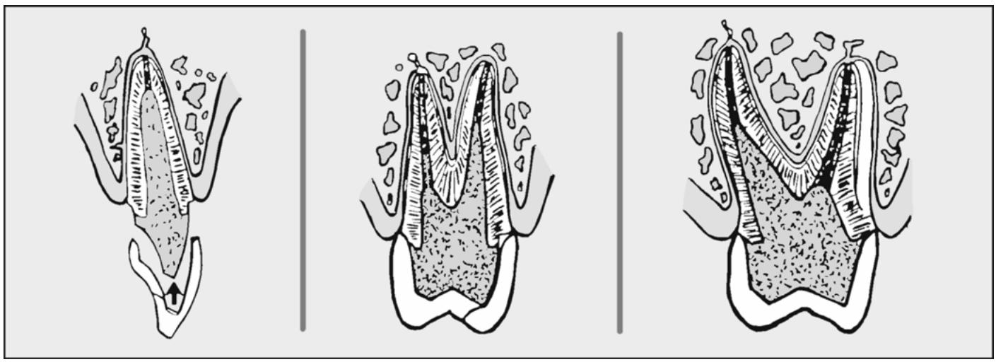
natural_image
Three diagrams showing tooth profiles with no text or symbols, illustrating dental or dental anatomy (no text or labels present)
1.79.1. Waxing. Using the indirect technique, patterns are more easily made of wax. A device is needed to strengthen the wax post portion of the pattern and to ensur e wax completely fills the root canal. A sprue between the tip of the post and the gutta-percha used to fill the root tip wou ld not be acceptable. To prevent this from happening, use a 14-gauge solid plastic sprue former or paper clipinside the canal (Figure 1.93).
1.79.1.1. Trim the tip of the plastic sprue former so it will exactly fit into the canal and reach the apical end of the preparation. Also, cut small notches into the sprue to aid in retention of the wax.
1.79.1.2. Liberally apply die separator to the inside of the preparation. Using an explorer or PKT No. 2, fill the apical end of the canal with dead soft wax (sprue wax, utility wax). Warm the sprue slightly and insert it into the wax completely (Figure 1.93-A). Wait until the wax cools and test the wax post for removal. Be sure each time the pattern is removed it is returned to the same place. Rewax the pattern if it has voids or if it breaks.
1.79.1.3. Add enough inlay wax to the coronal portion of the pattern to overbuild the core. Carve away the excess wax and refine the core pattern until it imitates the contours of an ideal crown preparation (Figure 1.93-B). Ensure the margin of the core is continuous with the canal preparation. NOTE: The final restoration will probably be a metal-ceramic crown. See Chapter 2 of this volume for details on amount of reduction needed for a metal-ceramic crown.
Figure 1.93. Post and Core Construction.
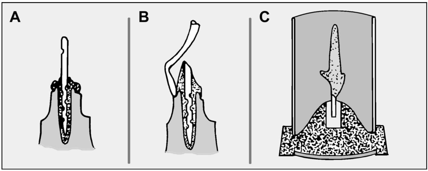
text_image
A
B
C
1.79.2. Spruing. Sprue the pattern on the incisal or occlusal surface (Figure 1.93-C).
1.79.3. Investing. Add 1 or 2 cc more water per package of investment to lessen the amount of mold expansion and thereby produce a smaller post and core that will h ave less ten dency to bind in the canal.
1.79.4. Burnout and Casting. Follow the conventional routine used with Type III gold alloys.
1.79.5. Finishing. Finish the casting as you would an inlay. Check the casting’s fit by gently seating it in the preparati on. Ifit binds in the canal or will no t seat completely, coat the po st with disclosing medium and relieve any shiny spots on the casting that are disclosed by the medium. Once the casting completely seats in the prepara tion, desprue the post and core. Recontour the
sprue attachment area and finish the casting with mounted stones or sandpaper discs. Give the core part of the casting a final satin finish with a rubber wheel.
DentalTechnology.org is dedicated to preserving, teaching, and advancing the craft of dental technology.
This resource is made possible by Russellville Dental Lab, a full-service dental laboratory in Russellville, Kentucky, serving clinicians across the USA for more than 70 years.