¶ Chapter 2 — METAL-CERAMIC RESTORATIONS
Reference Edition
This chapter is part of the Air Force Dental Laboratory Manual (2005) – Digitally Restored Edition.
This edition preserves the original publication while correcting OCR errors, restoring formatting, reconstructing damaged tables where necessary, and improving digital readability.
The technical content has not been rewritten, modernized, expanded, or altered.
It is provided as a professional reference. Modern instructional material is published separately throughout DentalTechnology.org.
¶ Section 2A — Metal-Ceramic System
¶ 2.1. Overview
The information presented in this section applies to the noble-metal alloy systems and does not necessarily reflect the characteristics of base metal alloy systems. A metal-ceramic restoration is one in which veneer porcelain is bonded to an underlying metal substructure. This type of restorationenables the dentist to provide the patient the estheticand biological advantages of porcelain plus the fit, strength, and durability of a ceramic alloy. Also, porcelain is impervious to mouth fluids, color stable, resistant to abrasion, and causes minimal tissue reaction.
¶ 2.2. Physical Characteristics of the Metal-Ceramic System
2.2.1. Strength of the Bond. The role of each bonding mechanism between porcelain and metal is not clearly defined. Three factors influence the bonding of porcelain to metal:
2.2.1.1. A chemical bondoccurs when oxides, primarily tin oxide, on the metal surface fuse with the porcelain during firing.
2.2.1.2. A compression bond exists when the cooling metal shrinks, drawing the porcelain together and placing the veneer in a state of compression. The metal substructure should be designed to take full advantage of the compressive nature of porcelain.
2.2.1.3. A mechanical bond results from the gripping action of the porcelain that has solidified in the microscopic grooves and undercuts of the metal surface. The bond strength of porcelain fused to metal is greater than the tensile strength of the porcelain itself. A break wouldoccur through the porcelain before the porcelain and metal pull apart.
2.2.2. Coefficients of Thermal Expansion.
2.2.2.1. The success of using one manufacturer’s porcelain system withanother’s ceramic alloy may be measured in terms of their coefficients of thermal expansion. The coefficients of thermal expansion of the porcelain and the metal must be relatively close if the porcelain is toremain firmly bonded after the completed restoration has cooled.
2.2.2.2. Although the expansion coefficients of the porcelain and metal are similar, they are not the same. Porcelain is strongest when it is compressed. Manufacturers deliberately lower the coefficient of expansion of the porcelain slightly in relation to the metal. (The porcelain expands, or similarly shrinks, less than the metal.) After firing and subsequent cooling, the porcelain is bonded to the metal in a state of compression. If the opposite conditionexists, the porcelain, after cooling, would be in a state of tension and the veneer would likely crack. It is for this reason that the porcelain and alloy chosen should be a compatible system.
2.2.3. Strength of the Substructure. When a porcelain veneer is bonded to metal, any deformation of the metal may cause the brittle porcelain to fracture. Metal frameworks must be strong enough to resist any deformation under an occlusal load. An alloy’s strength does not depend solely on how its molecules are put together. Strength also depends on the bulk and design of the metal frame. As the length of the span increases, an FPD must have a thicker cross-section and the thickness increase must be in line with occlusal loading. In designing posterior FPDs with veneered pontics, one reason for covering the occlusal and tissue contacting surfaces with metal is that the correspondingly greater bulk of metal will increase resistance to deformation and decrease the possibility of porcelain fracture.
2.2.4. Melting Range of Ceramic Alloys. Most low-fusing porcelains mature between 870 to 1065 °C. Because the melting range of the conventional golds used in dentistry is approximately the same temperature, it is necessary to have an alloy with a higher melting range to withstand the firing temperature of dental porcelain without deforming. Several ceramic alloys are formulated with a casting range from 1150 to 1360 °C. The technician can bond low-fusing porcelain to these ceramic alloys without any deformation of the framework.
2.2.5. Thickness of the Veneer.
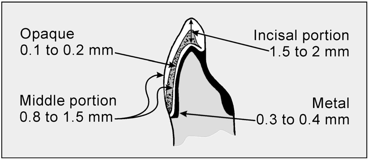
2.2.5.1. The combined thickness of metal and porcelain on the facial surface of metal-ceramic crowns should be at least 1.2 to 1.5 mm thick to meet minimum strength and shade requirements (Figure 2.1). There should be at least 0.3 mm metal thickness in the porcelain veneer areas to keep the substructure from flexing during seating or occlusal load, thus fracturing the applied porcelain. The opaque layer needs to be 0.1 to 0.2 mm thick to perform its masking function. The dentin and enamel porcelain should be a minimum of 0.8 mm thick with 1 mm being ideal to reproduce the desired shade. More porcelain may be needed in the incisal portion because of added translucency necessary in this area.
Figure 2.1. Veneer and Metal Thickness.
text_image
Opaque
0.1 to 0.2 mm
Incisal portion
1.5 to 2 mm
Middle portion
0.8 to 1.5 mm
Metal
0.3 to 0.4 mm
2.2.5.2. The technician can place the required metal and porcelain thickness on a stone die regardless of the amount of tooth reduction done by the dentist. However, if the tooth’s normal contour is to be restored, the dentist is obligated to reduce the facial surface of the toothat least 1.2 mm to ensure there is room for the minimal thickness of metal and porcelain.
2.2.5.3. Pontics should be made so the bulk of the pontic is composed of metal evenly veneered with 1 to 1.5 mm of porcelain. Metal-ceramic frameworks should be made so porcelain can be uniformly applied in a thickness that does not exceed 1.5 mm on the facial or 2 mm on the incisal. Try to keep the porcelain to a minimum thickness without sacrificing esthetics. A thin, uniform thickness of porcelain supported by a rigid substructure offers the most strength.
2.2.5.4. The relative thickness of the metal substructure, opaque, dentin and enamel porcelains depend on the type of ceramic alloy and porcelain used. For example, metal substructures made from high-gold content alloys need to be at least 0.5 mm thick to adequately support the. porcelain. The minimum thicknesses listed above are not absolute and will not apply in every given situation. Strength requirements also depend on the design and extent of the restoration.
¶ Section 2B — Color and Shade Selection
¶ 2.3. Color
Visible light is the range of the electromagnetic spectrum that is visible to the human eye. The visible light range includes violet, blue, green, yellow, orange, and red wavelengths (spectrums). Color is defined as the physical modifications of light by colorants, observed by the human eye and interpreted by the brain. The many variables involved in producing color will be discussed in this section.
2.3.1. Dimensions of Color.
2.3.1.1. Just as an object can be described by its dimensions (length, width, and depth), color can be described by its dimensions (hue, chroma, and value)
2.3.1.2. Hue denotes the name or type of color. For example, red, orange, and blue are all names for colors.
2.3.1.3. Chroma is the amount of saturation of a hue. For example, an object that is intensely red is higher in chroma than pale pink.
2.3.1.4. Value, sometimes referred to as brightness or reflectivity, can be defined as the relative whiteness or blackness of a hue. High value is more white or reflective. When relating to a black and white photograph to describing value, a light blue object next to a tan coloredobject may appear as identical levels of gray. Value is probably the most important dimension of color to the dentist and technician. If the value of a restoration and the teeth match, small differences in the hue and chroma will not usually be noticed, but a crown of higher value will be more reflective and readily visible.
2.3.2. Subtractive Color System. This system is used with pigmented objects and is useful in characterizing fixed prosthodontic restorations. When light reflects from a pigmented object, some wavelengths are absorbed or subtracted. The color you see is the wavelength reflected from the object. The red from astop signsubtracts all wavelengths except red. The three primary hues are red, yellow, and blue. They are the basis of the subtractive color system and cannot be reproduced by mixing other hues. As their names imply, secondary hues are produced by mixing primary hues. They are orange, green, and violet.
2.3.3. Complementary Colors.
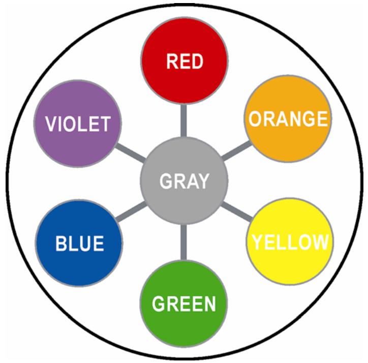
2.3.3.1. Any hue that is opposite another hue on the color wheel (Figure 2.2) is called a complementary hue. Orange and blue and yellow and violet are the two most common complementary color relationships used in reference to fixed restorations.
2.3.3.2. Adjusting the shade is rarely as simple as adding a hue that is lacking. More often it also involves reducing an apparent excess of chroma in a given hue or making an adjustment in value as well. Complementary hues become an important part of this process.
2.3.3.3. When two complementary hues of equal chroma are mixed together, they produce a neutral gray. This can be a very effective way to reduce chroma or lower value.
2.3.3.4. Complementary hues can also be used to intensify the chroma of the dominant hue present. When two complementary hues are placed side by side, each intensifies the other’s chroma. For instance, placing blue stain along the cervical, mesial, and distal boundaries of a predominantly yellow tooth may make the tooth appear more yellow.
Figure 2.2. Color Wheel.
2.3.4. Color Variables. Many factors come into play when observing, recording, and reproducing a selected tooth shade. Be aware of the following environmental influences when evaluating the color of a tooth:
2.3.4.1. Object Variables. When looking at an object such as a crown, the color of the object may contrast with the surroundings. A green object placed on a yellow background will appear blue. The same green object placed on a blue background will appear yellow. Because blue and yellow together produce green, placement of a green object on one of these colors contrasts the remaining color. This same effect can also be applied to the value of an object. For example, a gray object on a black background will appear lighter; on a white background, the same object would appear darker.
2.3.4.2. Light Source Variables. Without light, color cannot exist. Each light source, whether it is daylight, fluorescent light, or color-corrected light, emits wavelengths of varying color, temperature, and intensity. Cool white fluorescentor normal office fluorescent bulbs usually emit light high in blue and green. Incandescent bulbs are high in yellow and red. Daylight is considered by many to be the best light source for comparing colors. However, daylight varies in intensity and quality depending on atmospheric conditions and time of day. The light that produces consistent illumination and negates using daylight is the color-corrected light or a commercially available, hand-held light for taking shades. These lights are made to emit a broader spectrum of light for better color comparisons.
2.3.4.3. Metamerism. This phenomenon occurs when stimuli reaching the eye causes two objects to match in color under certain lighting conditions. To avoid metamerism, compare objects in the same or similar light sources and build color modifications internally.
2.3.4.4. Cone Fatigue. Avoid staring at the teeth or a shade guide for long periods of time. After staring at a particular color, the retinal cones in your eyes become desensitized to that color. If you stare at a blue card, blue will deplete the retinal chemical balance for blue, and
orange will be easily seen. An opposite reaction will occur if you stared at a yellow-orange card. Varying your gaze and looking at a variety of colors is less likely to desensitize any one color. Do not use the blue card as a background for comparing shades. White is the best background for extraoral comparisons.
¶ 2.4. Selecting a Shade
As a minimum, the dentist will select the shade for the restoration and include this information on the prescription form. The technician will then interpret the prescription and make the restoration, duplicating the shade selected. Shade selection is a dentist’s responsibility; but, when possible, the individual who will make the restoration should be involved in the shade selection process. Whether selecting a shade or comparing the restoration to a shade tab, the following principles apply:
2.4.1. Take the shade in a neutrally colored room, the porcelain room, or a room with some outside light available. If possible, use a color-corrected light as the primary light source. Cover bright or high chroma clothing with a patient napkin and have lipstick removed. Choose a shade guide compatibleto your porcelain system and if possible arrange guides by value. Choose a shade with asimilar value regardless of shade. Choosing value is difficult for many people, reducing the amount of light entering the eye by squinting can help discern reflectivity.
2.4.2. Once satisfied that the value is correct, try to determine the dominant hue of the tooth. Natural teeth have dominant hues in the yellow to yellow-orange range. With the Vita Lumin® shade guide, the A range is yellow-red, the B range is predominately yellow, the C range is a gray-yellow, and the D range is gray yellow-red in color. Other shade guide systems may have varying hues andorganization. If choosing the hue is difficult, compare areas thin in enamel such as the lingual, proximal, or cervical regions of a tooth.
2.4.3. For the last comparison, determine the chroma. The selected chroma level should closely correspond to the previous value selection. For example, a value selection of D3 with a hue and chroma selection of A3 is almost ideal. These two shade tabs are adjacent to each other on the value scale. Use of either shade would probably work fine, so choose the closest match.
2.4.4. If no satisfactory shade match is available, select a shade tab that is higher in value and lower in chroma. A higher value shade can be lowered (adjusted) more easily without loss of translucency. Any deviation in the final restoration should be toward a lower value because a darker crown will be less noticeable over a lighter crown.
2.4.5. The shade selection process improves with practice. Develop a habit of viewing the shade selection at various distances—close up and then far away. If there are any color defects or abnormalities, be sure to include these on the prescription along withany characteristics such as glaze level and surface texture.
¶ Section 2C — Substructure Design and Fabrication
¶ 2.5. Factors in Substructure Design
To a great extent, the shape of the metal substructure seriously affects the stresses that develop in the porcelain. As it is being fired, porcelain tries to become a sphere. This results in the porcelain drawing to the metal structure; and when the restoration has cooled, the porcelain is in a compressive state. If the metal’s surface is sharp or uneven, tensile stresses are created in the porcelain as it cools and may cause the veneer tofail.
2.5.1. Surface Form. The primary bond between porcelain and metal is chemical in nature, but mechanical bonding also plays an important role. Bond strength overall seems best when the porcelain-bearing metal surfaces are gently rounded. Avoid producing corners, angles, points, or deep concavities on the porcelain-bearing surfaces. Sharp angles and points will create stresses in the porcelain, causing it to fracture. Deep concavities are a problem because the porcelain is likely to shrink away from these areas during firing towards its greatest bulk. Due to the tenacious bond strength between porcelain and metal, mechanical retention in the form of beads, lugs, or peripheral boxing (acrylic resin veneer) is not required and, if present, would make the porcelain more susceptible to fracture.
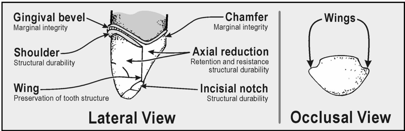
2.5.1.1. Tooth Preparation. A typical tooth preparation for anterior restorations combines a facial shoulder margin style with a lingual chamfer or knife-edge margin (Figure 2.3). The amount of tooth surface removed from the facial surface is about 1.5 to 2.0 mm, and only about half this thickness is removed from the lingual portion. An elevated ridge, called a wing, results from the differences in these depths and is usually located lingual to the proximal contact area. This preparation form significantly affects the design of the preparation.
Figure 2.3. Typical Tooth Preparation for Anterior Metal-Ceramic Restorations.
2.5.1.2. Full Contour Wax-Up. The porcelain-bearing surfaces of substructures should closely parallel the finished contours of the porcelain veneers. Remember, porcelain is strongest when it is applied in a thin uniform thickness. To do this, wax the restorations to full contour and uniformly cut back the wax patterns. Then (and only then) canyou be sure of a uniform thickness of porcelain and know where to place the metal-ceramic junction (commonly referred to as porcelain-to-metal junction or finish line). If the porcelain is left unsupported, tworesults will likely happen—the porcelain may fracture due to stress or thermal shock or subsurface porosity may increase in the thicker sections, weakening the porcelain.
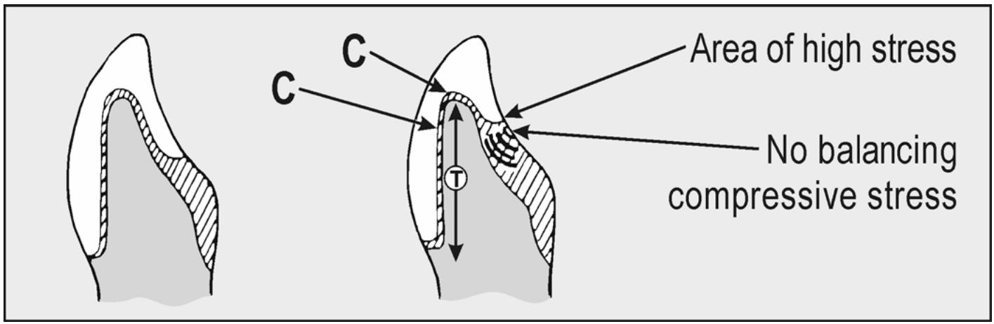
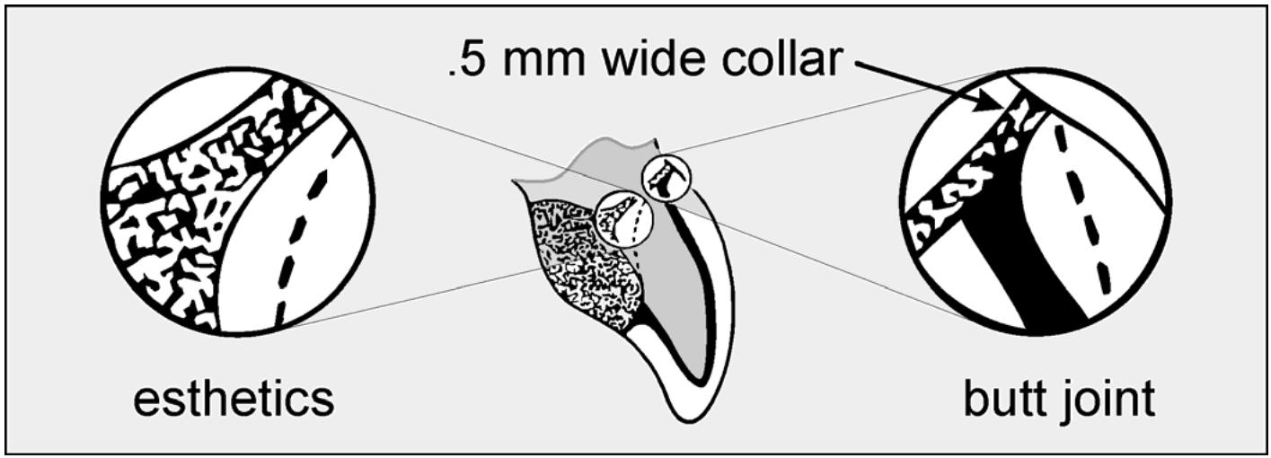
2.5.1.3. Finish Lines. When wax patterns are made, finish lines should be placed in a position to take full advantage of the compressive strength (paragraph 2.2) of the porcelain. Designs that do not let the porcelain wrap around the structure are not recommended because the porcelain does not have anything to grasp or holdon to. With this design, the risk of fracture is much greater than when the finish line is kept as low as possible (Figure 2.4). All junctions between porcelain and metal on the external surface of a restoration should be as close to a 90-degree angle as possible (Figure 2.5). The porcelain must not be feathered at the porcelain-to-metal junction because the porcelain would be more likely to chip in function or “flake off” during seating.
2.5.1.4. Cervical Collar. A cervical collar of metal is recommended for strength and support of the porcelain in the shoulder area. With beveled shoulder preparations, the width of the facial bevel determines the width of the cervical collar. A 1 mm wide bevel requires a 1 mm wide cervical collar. At a minimum, provide a 0.5 mm cervical collar as a routine practice.
Figure 2.4. Balancing the Compressive Strength of Porcelain.
text_image
Area of high stress
C
C
T
No balancing
compressive stress
Figure 2.5. Creating a 90-Degree Angle Butt Joint for Porcelain.
text_image
esthetics.5 mm wide collar
butt joint
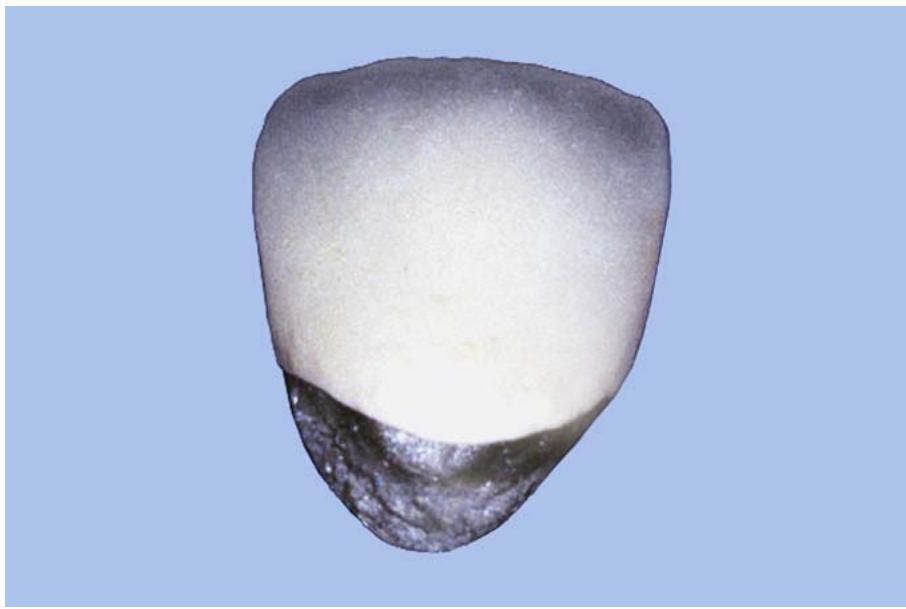
2.5.1.5. Porcelain Margins. Sometimes, the placement of facial metal margins subgingivally creates problems. If the patient has thin translucent tissue, a dark shadow may be visible at the gum line. This dark shadow reflected at the cervical collar is considered unattractive. One way to prevent this problem is to make crowns without metal collars (colla rless) (Figure 2.6). The dentist cuts ashoulder preparati on for the porcelain margin techni que. An altern ative to this design requires the metal and porcelain to be finished to a knife edge at the margin (known as a disappearing margin). However, this design is not recommended because the porcelain could fracture while the crown is being seated. Do not try to apply porcelain over a long beveled shoulder that was originally prepared for a cervical collar.
2.5.2. Occlusal Contacts. As a rule, never place the metal-ceramic junction at an MI contact point or area because porcelain fracture would be inevitable. In fact, do not place the junction where the opposing tooth would ride across it during an excursion. This situation may also cause the porcelain toflake, especially if the substructure is poorly designed.
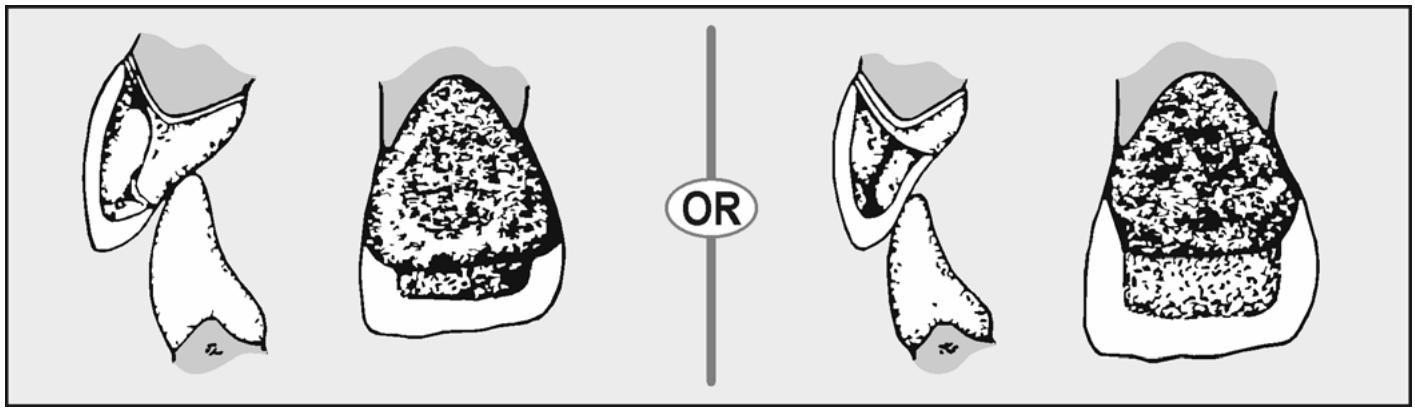
2.5.2.1. Anterior Design. Because occlusal contacts should not occur at the metal-ceramic junction, the contact must occur either on the metal framework or on the porcelain (Figure 2.7). Keep the metal-ceramic junction well away (2 mm) from the MI contact point. If you don’t, the metal may flex and cause the porcelain to fracture.
Figure 2.6. Porcelain Shoulder Margin.
natural_image
Close-up of a tooth with a white gum layer and dark surrounding area (no text or symbols)
Figure 2.7. Metal-Ceramic Design for Anterior Crowns.
natural_image
Four anatomical diagrams showing different shapes with a central 'OR' label (no text or symbols beyond the label)
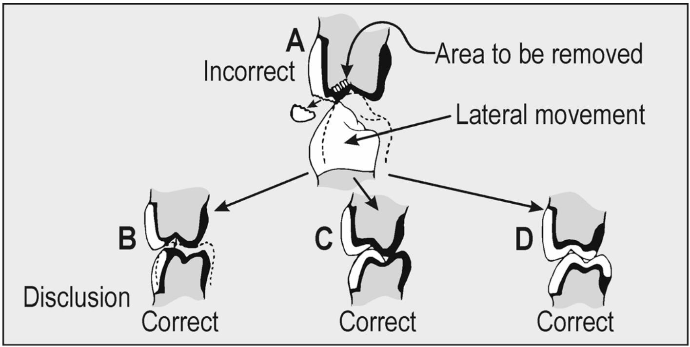
2.5.2.2. Posterior Design (Figure 2.8)
2.5.2.2.1. In the maxillary arch, the posterior design is fairly simple because the shearing cusps do not occlude in MI nor should they function during an excursion. On a premolar, the metal-ceramic junction is located across the buccal triangular ridge. If the metal-ceramic junction is placed too close to the fossa, the porcelain will fracture (Figuare 2.8 -A). The pattern sho uld be wax ed witheno ugh space for porcelain or adequate metal contact to support porcelain.
2.5.2.2.2. With the mandibular arch, the problem of where to place the metal-ceramic junction becomes more difficult depending on the situation. In Figure 2.8-B, the mandibular buccal cusps are made of metal to lessen the risk of porcelain fracturing. This design is not very esthetic; it should be used only when the patient’s exhibits group function occlusion in lateral movements. If mutually protected or anterior guidance occlusion is provided, the designshown in Figure 2.8-C or -D is recommended. Also notice that like materials, metalto-metal and porcelain-to-porcelain, are made to contactone another in occlusion.
Figure 2.8. Placement of the Metal-Ceramic Junction on Posterior Occlusals.
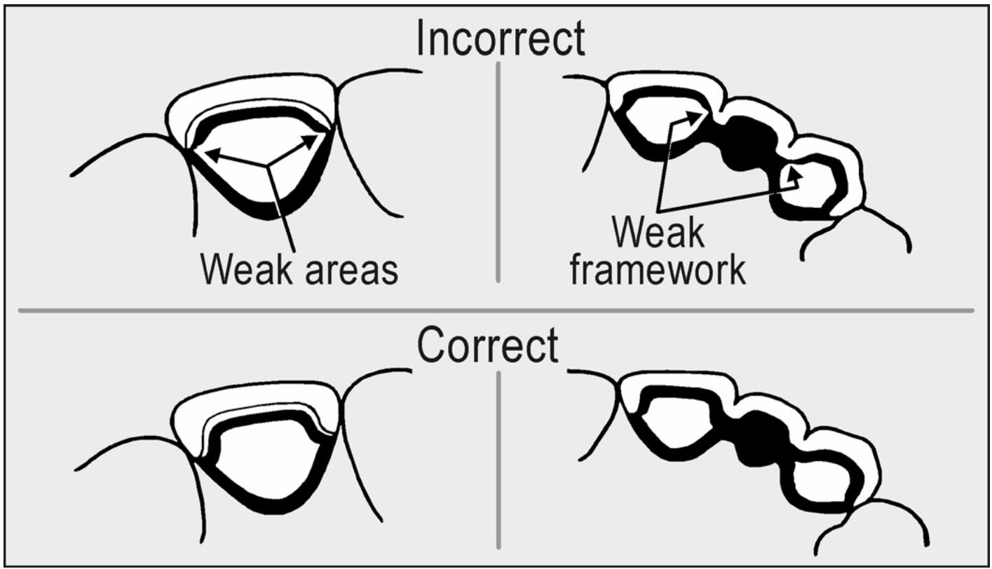
2.5.3. Proximal Contacts. The proximal contacts of anterior restorations should be in porcelain. This is the most esthetic design, and it offers the most latitude in contouring the veneer. Do not place the metal-ceramic junction lingually as far as the proximal wing of the preparation because this would result in a thin area and thereby weaken the framework (see Figure 2.9). For premolars, place the mesial contact in porcelain for esthetic reasons. The distal contact may be in metal. Generally, molar contacts are made in metal.
2.5.4. FPD Design.
2.5.4.1. All the principles of framework design that apply to single units would also apply to FPDs. In addition, FPD frameworks require more strength because of connectors. Frameworks must not flex or bend, causing the porcelain to fracture. There must be a large enough mass of metal to ensure rigidity, plus uniform thickness of porcelain to prevent uneven stress concentrations in the porcelain.
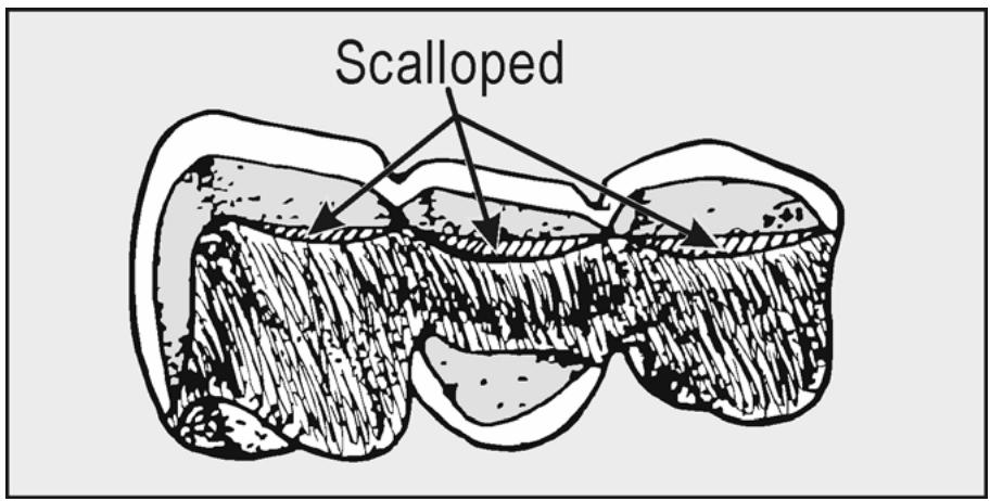
2.5.4.2. The typical design for an anterior FPD is in Figure 2.10. Notice the continuous width of metal across the lingual surfaces. The lingual finish line may also be scalloped to add lengthand bulk in the connectors. If needed, this connector design is also easier to solder. Also, be sure to make the connectors wide enough buccal-lingually for adequate strength.
2.5.4.3. Porcelain coverage of the pontics is basically the same as for retainers. EXCEPTIONS: Porcelain is applied to ridge areas for better esthetics and to prevent possible tissue irritation, and the porcelain veneers of pontics should be continuous with the veneers of retainers.
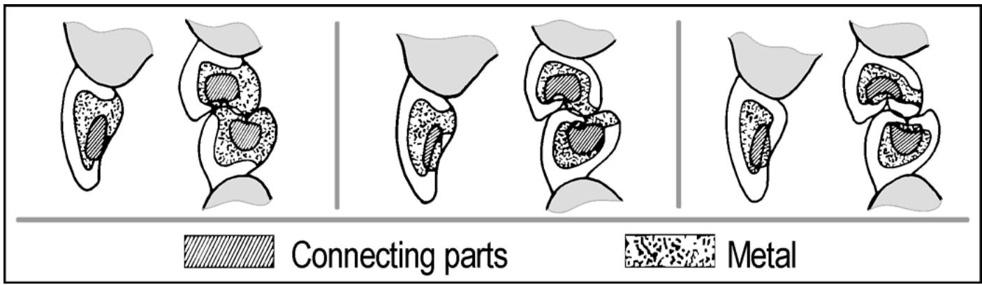
2.5.4.4. From a mesial or distal view, the contour of the metal surface must appear to closely follow the contour of the porcelain veneer (Figure 2.11). At least 1 mm of porcelain should cover the facial surface, while an absolute minimum of 0.5 mm of coverage is neededon the pontic’s tissue side. Possible irritation of the gingival tissues could result from contact with a rough metal-ceramic junction. Therefore, the pontic’s lingual finish line is placed lingually and incisally to the crestof the ridge.
Figure 2.9. Improper Placement of the Metal-Ceramic Junction.
text_image
Incorrect
Weak areas
Weak framework
Correct
Figure 2.10. Typical Metal-Ceramic Substructure for Anterior FPDs.
text_image
Scalloped
¶ 2.6. Waxing
Patterns should follow the designs described in paragraph 2.5. Wax all single complete crown and multiple complete crown retainer patterns to a minimum thickness of 0.4 mm in the veneer areas. This thickness is needed to strengthen the wax pattern and provide enough bulk to ensure a complete casting. The wax has to have uniform thickne ss and be wrinkle free if the pattern is to cast without holes or voids.
2.6.1. Coping Preparation.
2.6.1.1. One of the many ways to lay down a well-adapted coping for this kind of pattern is to dip the die into molten wax until the wax completely covers the cervical margin. Use a wax specifically made for wax dipping. Dip the die as many times as it takes to get the desired thickness. Adjust your technique so one coat of wax will equal 0.4 mm.
Figure 2.11. Metal-Ceramic Design for Pontics.
text_image
Connecting parts
Metal
2.6.1.2. Wax the margins and cervical area, using regular inlay wax or follow the dual wax technique, using a harder inlay wax (type A)
Use the dual wax technique because the harder inlay wax used for the marginal area resists distortion. You can also wax copings freehand, but use care to prevent internal wrinkles and voids in the pattern.
2.6.1.3. After making the coping, remove it to ensure that undercuts do not prevent removal of the completed pattern. Complete the full contour wax-up, using the wax-added technique mentioned in Section 1J.
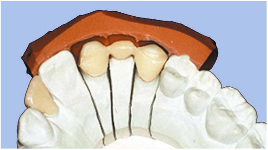
2.6.2. Cutback Technique. Study the full contour wax-up carefully. Make mental notes about the occlusion and overall appearance of the waxup. Better still, make an impression of the wax-up to serve as a guide during the porcelain application procedures. An ideal method is to make a facial index of the full contour wax-up with asilicone putty impression material. Pour this index with stone to make a perm anent recordof the wax-up and the opposing teeth. Cut the index in half below the incisal (occlusal) edge to expose the imp ression from an occlusal view. Then, use it to check the amount of cut back on the wax substructure (Figure 2.12). However, you will not be able to use this index during the porcelain application st ep so be sure to mark the widthand length of the restorations on the opposing cast for future reference.
Figure 2.12. Facial Core Used To Check Cutback.
natural_image
Close-up of a dental model showing upper and lower teeth with gum tissue (no text or symbols visible)
2.6.3. Single Crown Cutback (Figure 2.13)
2.6.3.1. The first step in performing the veneer cut back area is to scribe the outline of that area on the pattern using a No. 25 blade (Figure 2.13-A). Place the proximal metal-ceramic junction of anterior units as far lingual as possible.
2.6.3.2. Using a sharp instrument, carve away 1.5 mm from the incisal edge of the pattern (Figure 2.13-B)
Then use a discoid carver to provide a nice, smooth butt joint between the metal and the porcelain and to also place vertical grooves (depth cuts) in the center of the labial surface (Figure 2.13-C). Use these grooves to measure the depth of wax in the veneer area, which should be at least 1 mm deep.
Figure 2.13. Cutback Technique for Crown Patterns.
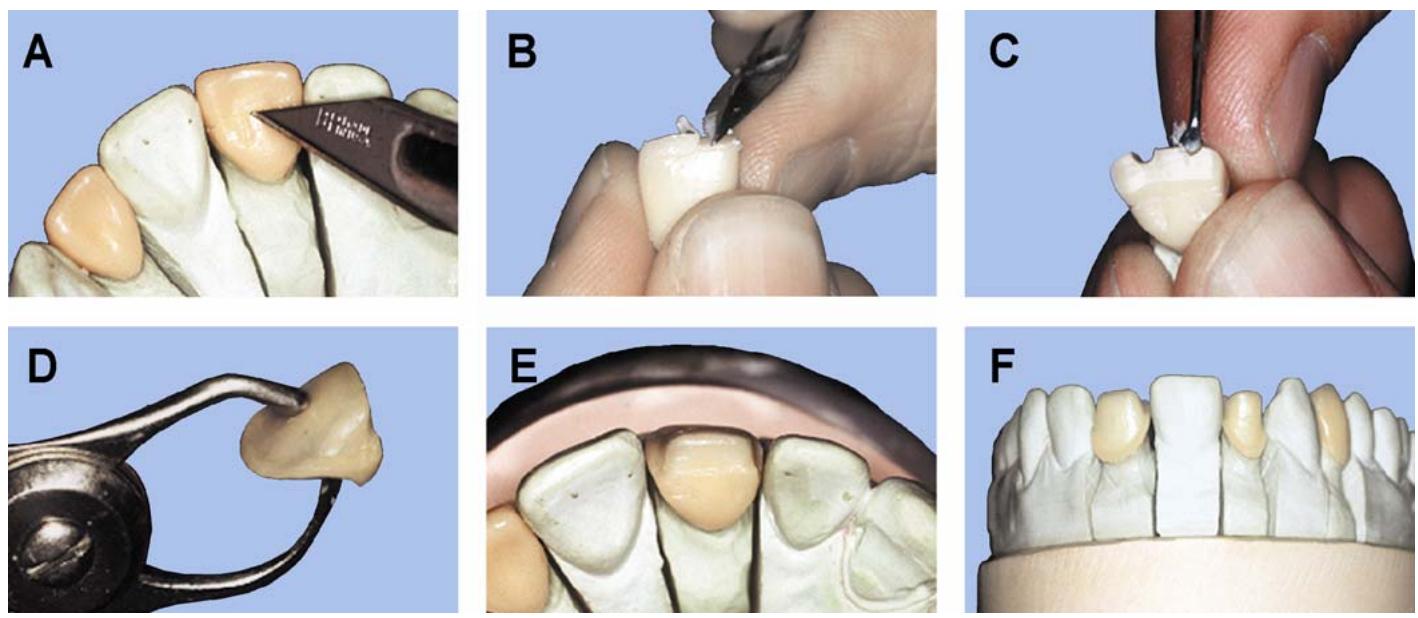
2.6.3.3. Remove the remaining wax with a #25 blade or similar instrument, leaving a smooth veneer surface with a sharp clean metal ceramic junction. If the crown is to have a metal collar, leave a 1.5 mm cervical collar on the facial one-half of the pattern. This width helps to ensure strength of the pattern and complete casting of the facial marginal area. Later, reduce the width of the collar in metal to the minimum 0.3 mm thickness (a bulk that resists distortion when the porcelain cools from its firing temperature)
2.6.3.4. If a porcelain margin is prescribed remove the wax from the facial margin area to the junction of the facial axial wall of the wax pattern and the shoulder, leaving the shoulder margin exposed.
2.6.3.5. Use a wax gauge to check the thickness of the facial cut back (Figure 2.13-D)
The wax should measure at least 0.4 mm. If not, add wax to provide enough bulk. Also inspect the inside of the pattern for thin areas of wax that might cause an incomplete casting. Smooth the completed pattern, being careful not to destroy the nice, crisp finish lines or intricate anatomy.
2.6.3.6. Replace the die and pattern on the working cast and check the occlusion and placement of finish lines. From various angles (mesial, distal, and occlusal profiles), inspect the cut back for amount of reduction (Figure 2.1 3-E and -F). Remember, the metal surface should parallel the contour of the finished restoration. There are usually two areas of concern, the mesiodistal curvature and the occlus ogingival curvature of the facial surfaces of teeth. Almost always, the
wax pattern should be “rolled in” on these surfaces, especially anterior units. The tendency is for novice technicians to make their substructures “box-like” without allowing for the natural esthetic curvature of all teeth.
2.6.3.7. The final step is to adapt the margins before spruing and investing. Carefully remove the wax pattern and check for defects such as broken or frayed margins, overextended margins, and short margins. Use a microscope to check the margin while the wax-up is on the die. Some technicians also prefer to att ach a small wax knob to the lingual collar. They use this knob for removing the crown during the try-in and, in some instances, as a h older while build ing porcelain layers.
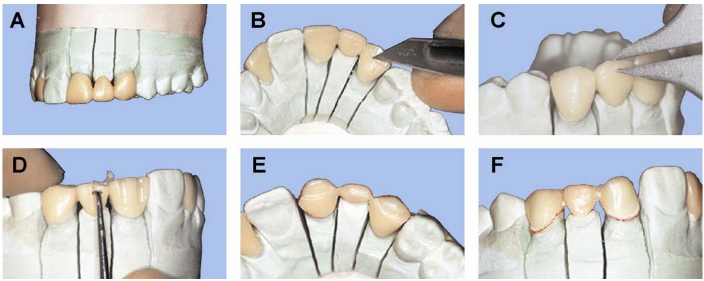
2.6.4. FPD Patterns. Waxing multiple unit wax substructures is much like waxing single units. Each retainer is reduced the same way an individual unit is (Figure 2.14). The difficulty lies in the cut back of the pontics. Either carefully cut back the pontic while it is attach ed to one of the retainers or section the pontic from its retainers and cut back the pontic individually. Bear in mind thatonce you remove the pontic, you must repos ition it precisely so you do not destroy the occlusal relationships originally established. Review paragraph 2.5.4 for a description of FPD substructure design.
Figure 2.14. Cutback Technique for FPD Patterns.
¶ 2.7. Spruing
For the most part, metal-ceramic substructure patterns can be sprued the same as conventional alloys, but lower density and increased melting range make the metal-ceramic alloys more susceptible to casting porosity. This porosity, whether deep inside the metal or on the surface, can create subsurface bubbles in the porcelain, which will weaken the veneer. Due to the sensitive nature of these alloys, it would be better to ad apt the standard spruing, investing, and casting techniques to coincide with the particular metal-ceramic alloy being used.
2.7.1. General Observations. To make the best possible castings, follow these principles: (1) make sure the sprue former’s diameter corresponds to the volume of the pattern (larger patterns need thicker sprues); (2) when using direct spruing, avoid constrictions in the sprue; and (3) position patterns in the investment mold so they are 3 to 6 mm from the top and their reservoirs are within the thermal zone.
2.7.2. Sprue Former Attachment.
2.7.2.1. Single Units.
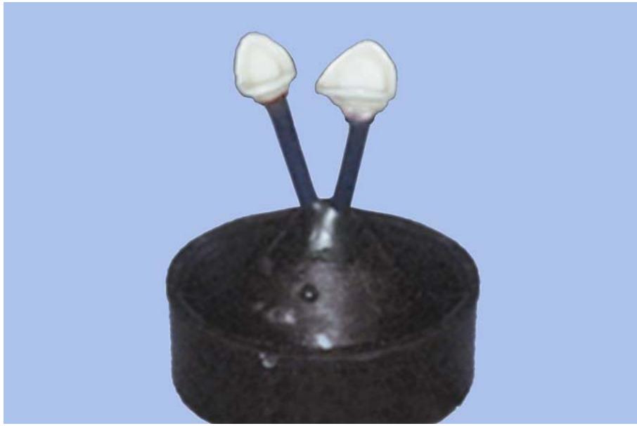
2.7.2.1.1. Sprue single anterior units on the incisal edge (Figure 2.15)
This way, you can place the sprue former at an angle that will direct molten metal into the thinnest areas of the casting as well as the thick areas. If the wax is thin in an area, add a small ridge of wax to that surface to act as an auxiliary sprue. Normally, copings are thick eno ugh to allow for a complete casting. Spruing to the veneer area positions the sprue away from the margins and makes finishing a lot easier. Sp rue posterior wax patterns on the lingual cusp because of their large bulk. NOTE: This method may distort prev iously establishedocclusal relationships. To preserve occlusal contacts on maxillary waxups, sprue to the facial cut back area, taking care to direct the flow of metal across the occlusal tab le, toward the thicker areas.
Figure 2.15. Direct Spruing of Wax Substructure Patterns.
natural_image
Black ceramic pot with two white ceramic spikes mounted on a black base, against a plain blue background (no text or symbols)
2.7.2.1.2. Most single unit castings can be made from a single sprue. Rarely will a wax pattern require an auxiliary sprue former. Judge each case on its individual merits. Remember the following rule: sprue size and sprue placement depends on the volume of the wax pattern. Normally, the sprue former is made of wax and is at least 10 gauge in diameter.
2.7.2.2. FPD Patterns. The most common ways of spruing FPDs and multiple single units involve the indirect and direct methods. For best results, use the indirect spruing method described in paragraph 1.52.4.3. Placement of pattern sprues is the same as paragraph 2.7.2.1.
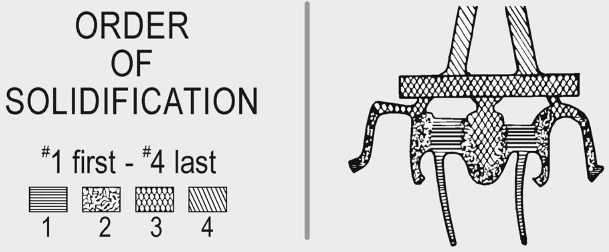
2.7.3. Chill Vents. Use chill vents to remove gases from the mold and to transfer heat away from the casting. The logical placement of chill vents is on the bulkiest areas of the wax patterns—the connectors (Figure 2.16). To construct a chill vent, attach an 18-gauge round wax wire about 6 mm long to each connector. This chill vent will draw heat away from the ponticand connector, preventing porosity in those areas.
Figure 2.16. Placement of Chill Vents on a Substructure Pattern.
2.7.4. Pattern Position.
2.7.4.1. Wax patterns should be 3 to 6 mm from the end of the ring so gases can escape through the porous investment as the rushing metal enters the mold. The chance of back-pressure porosity or an incomplete casting increases if this gas is not eliminated. Because ph osphatebonded investments are stronger than gypsum -bonded investments, the danger of the mold cracking is not as great and strengthis not a problem.
2.7.4.2. Another factor involves placement of patterns outside the thermal zone (Figure 2.17)
After the molten metal enters the mold, heat is transferred to the investment and concentrated in the center of the ring. The molten metal in this area (thermal center or thermal zone) will solidify last due to the hotter investment temperature. If the pattern is in the thermal zone, the feeder sprues could freeze before the pattern does. Place the pattern above or to one side of the thermal zone so that the casting will cool first and then the sprues.
Figure 2.17. Placement of Metal-Ceramic Patterns Outside the Thermal Zone.
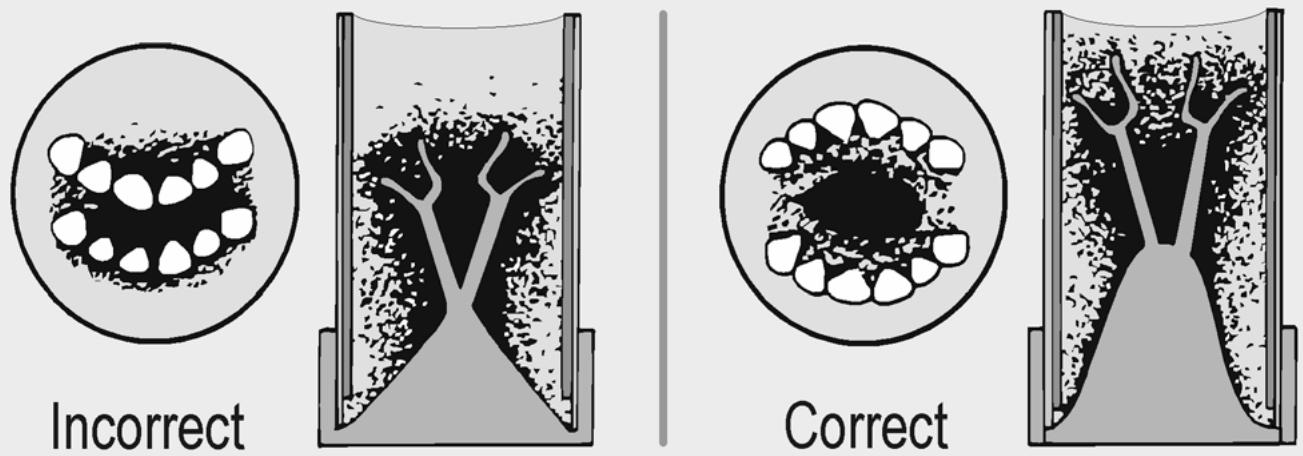
2.7.5. Orientation Dot. Besides depending on the force generated by a spring-wound casting arm to fill a burned-out mold, it is critical that the mold gets maximum benefit from the natural flow of molten metal during the casting procedure. Use the orientation dot method to indicate the relative position of the invested pattern inside a ring (paragraph 1.52.4.5).
¶ 2.8. Investing
The procedures used for investing metal-ceramic substructures are like those used with conventional gold castings. Phosphate-bonded investments must be used with ceramic alloys because of their high heat capabilities. Gypsum-bonded investments tend to break down when heated to temperatures greater than 1300 °F, giving off a sulfur gas. Not only is the strength and accuracy of the mold reduced by this breakdown, but sulfur gas can contaminate the alloy. Phosphate-bonded investments generally use a special liquid to control part of the expansion. This liquid is a colloidal silicate that can be diluted with water to provide various amounts of investment setting expansion. Undiluted liquid provides maximum setting expansion.
2.8.1. Mold Expansion. 2.8.1.1 When using phosphate-bonded investments, mold expansion is affected by:
2.8.1.1.1. Using more layers of asbestos substitute to line the casting ring.
2.8.1.1.2. Increasing the ratio of special liquid to water (more special liquid, more expansion)
2.8.1.1.3. Placing the investment in contact with water during setting (hygroscopic technique)
2.8.1.1.4. Burning out the mold at a higher temperature. If your castings are too large and you want to decrease the amount of expansion, try the opposite approach withany or all of the above methods.
2.8.1.2. The size of the casting ring affects the seating of castings. If too many patterns are crammed into one casting ring, expansion of the mold cavity will be uneven. Also, the castings will not be as precise nor will they fit their preparations. Therefore, be sure to use the larg er oval or round rings to produce FPDs that will seat more completely.
2.8.1.3. “Ringless” casting systems may also be used to gain added expansion. These systems do not use solid metal casting rings, and they vary in design from disposable wax forms to reusable plastic cylinders. The similarity all ringless casting systems share is unrestricted expansion during burnout.
2.8.2. Investment Procedures.
2.8.2.1. Use a separate mixing bowl for each type of investment (one for phosphate-bonded and one for gypsum-bonded investments)
Particles of other investment types can alter the chemical and physical properties of the mix. After mechanically mixing the ingredients together (manufacturer’s powder-to-liquid ratio and mixing times), continue to vibrate the mix under vacuum for an additional 15 seconds to remove ammonia gas that escapes as part of the chemical reaction taking place. Small metal nodules on the underside of the casting are a direct resultof this gas escaping.
2.8.2.2. It may also be necessary to change the mixing times because some mixing bowls become worn and will generate heat, causing the mix to suddenly harden. Either inspect the equipment and replace it or spatulate the mix for a shorter period of time. After investing the pattern, let the ring bench set for at least 60 minutes before burning out.
¶ 2.9. Burnout
2.9.1. Follow manufacturer’s directions for burnout temperature, rate of temperature climb, and hold time. Large rings will need more time according to their size. In any case, keep the investment at the recommended temperature until the color of the investment has completely whitened. A dark shadow in the center of the in vestment indicates carbon residue still left in the investment mold. The physical properties of some metal-ceramic alloys, especially high palladium content alloys, is greatly affected by carbon, making the use of a carbon-free investment desirable.
2.9.2. When using preformed plastic sprue formers, you should begin the burnout sequence gradually, before increasing the temperature to 1300 °F. Usually 30 minutes at 600 °F is sufficient to soften the plastic and allow the wax to run out. All burnout times and temperature should follow exactly the instructions of the investment’s manufacturer andof the particular alloy being used.
¶ 2.10. Casting
Ceramic metals are melted in a quartz or zircon-alumina crucible (made to withstand higher temperatures) and cast at 2300 to 2500 °F. Because of their lower densities and critical casting temperatures, they need more casting force. Instead of winding the casting arm only 3 1/2 to 4 times, wind it 4 1/2 to 5 times. Also, do not use casting flux during the melt because it can remove some of the trace elements in the alloy. Use a separate crucible to melt different types of alloys, thereby preventing alloy contamination.
2.10.1. Adjusting the Torch. Use a gas-oxygen casting torch with a multiorifice tip. Regulate the oxygen pressure to 8 pounds per square inch (psi), with the propane gas between 6 to 8 psi.
NOTE: Bottled propane under constant pressure produces a cleaner, hotter flame than natural gas. Use caution in lighting the torch. Always add oxygen to the gas flame and always remove oxygen from the gas flame in shutting off the torch. A correctly adjusted torch will produce a fairly soft, shower flame with the small blue reducing cones about 5 mm in length. The reducing nature of the flame indicates a slight excess in propane gas left unoxidized. Too much oxygen added to the flame causes oxygen gas absorption by the gold, and resulting in minute porosity throughout the casting. Hydrogen gas absorption by palladium is also a problem, especially in the higher content palladium alloys.
2.10.2. Melting the Alloy.
2.10.2.1. Preheat the crucible to a dull red to drive off moisture and prevent a cold spot at the base of the crucible. Alumina or quartz crucibles are self-glazing and do not need a liner.
Ceramic alloys are usually superheated (white hot—about 100 °F above their upper limit) before they are cast. Wear dark colored glasses to prevent an eye injury from the bright light of the hot metal.
2.10.2.2. Place the alloy in the crucible’s center and start the melt with the tip about 3 or 4 cm from the alloy. Continue heating the alloy, watching it change color from red, to orange, to dull white, to a mirror-like white. When the alloy is orange, transfer the ring from the furnace to the cradle. When the alloy is white hot and mirror-like, release the casting arm and let spin until the casting arm comes to a complete stop. Then remove the casting ring and let it bench cool.
2.10.2.3. When the ring is cool enough to handle, remove the casting and pick off most of the investment. Carefully air abrade the casting with aluminum oxide to remove any remaining investment.
2.10.3. Alternative Casting Method. Another casting method uses electric means of induction melting. Induction casting machines, similar to the Ticomatic, can be used to cast all types of ceramic alloys, but they are especially helpful when using base metal alloys. More information on induction casting is in Chapter 3, paragraph 3.8.2.
¶ 2.11. Finishing
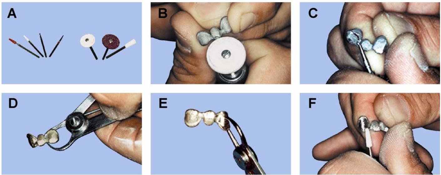
See Figure 2.18-A through -F. Overall, the three objectives in finishing the porcelain-bearing areas of castings for metal-ceramic restorations are to: (1) provide clean surfaces for the chemical bonding of porcelain and metal, (2) provide the ideal surface tex ture that will inc rease the wetting ac tion between the porcelain and metal, and (3) r eturn the metal subs tructure to p reviously established contours, taking full ad vantage of the porcelain’s physical characteristics (preparation of a porcelain-to-metal junction, placement of the junction, and overall design of the framework). Whilethe goal is to make a wax pattern thatonly requires m inimal finishing, chances are some recontouring may be needed as follows:
Figure 2.18. Surface Preparation of a Metal-Ceramic FPD.
2.11.1. Precautions.
2.11.1.1. Only use new finishing stones and burs or those used exclusively on a particular ceramic alloy to prepare porcelain-bearing surfaces (Figure 2.18-A). Indiscriminate use of finishing equipment can cause contamination by copper, silver, zinc, or chromium alloys. If the surface is unusually rou gh or is contaminated by using “dirty ” stones, the result may be severe blistering of the opaque layer.
2.11.1.2. Furthermore, only use abrasives that are fused together with a ceramic binder. Do not use rubber wheels or abrasives held together with epoxy resins or silica binders. If you are unsure about using an abrasive stone or point, place a sample of it in a porcelain furnace and fire to 1000 °C. If the abrasive does not turn to powder, it has a ceramic binder. Ceramic points either have carborundum or aluminum oxide as an abrasive particle; the latter abrasive is better.
2.11.1.3. Single-cut carbide burs make the best finishing instruments. They sharply cut the metal surface, producing lower roughness and very few undercuts or concavities. Try to grind on the castings in one direction only since criss-cross strokes may cause folding of the metal surface and impurities could become trapped.
2.11.2. Seating the Casting and Restoring Occlusion. Before despruing the casting, check to see that it fits the die and the margins are complete. Use a disc or abrasive wheel to recontour the sprue attachment area (Figure 2.18-B) and remove gross amounts of metal from the proximal contacts. D o not use “heatless” stones because they can contaminate the metal. Rubber the contacts smoothinto light contact with the adjacent teet h. If the occlu sion is h igh, reduce it to bring the restoration back into MI. Check the amount of clearance available for porcelain coverage in centric as well as through working, balancing, and protrusive excursions. If there is not enough space, reduce the metal substructure. NOTE: If the framework is to be presoldered (paragraph 2.27), do it at this time and before reducing the bulk metal.
2.11.3. Reducing Bulky Areas. (NOTE: Areas that normally require attention are adjacent to the metal-ceramic junction and connector areas.)
2.11.3.1. Use a fresh #8 carbide bur to prepare the metal-ceramic junction. Retrace the metal-ceramic junction, making a 90-degree angle preparation (Figure 2.18-C). The resulting finish line should be sharp and continuous. Everywhere porcelain is applied, it must end abruptly without feathering onto the metal and the shallow concavit y created must encirclethe metal support evenly and smoothly, reducing all traces of sharp angles or points.
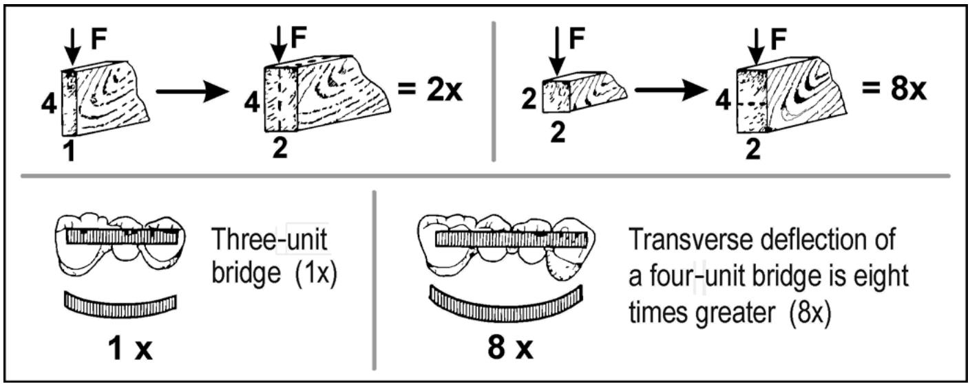
2.11.3.2. Make sure the connectors are strong enough to resist flexing of the metal, yet positioned where they will not compromise esthetics. Should the metal flex, the porcelain will fracture and the veneer will break off. Doubling the connectors width makes it twice as strong, but doubling its depthincreases the strength by a factor of eight. If a force (F) of 1 is applied to a three-unit FPD, flexing of the metal will only be minimal (Figure 2.19). However, if the same force (F) is applied to a four-unit FPD, the amount the metal flexes will be eight times greater. The minimum width of a connector for a three-unit FPD is 2.5 mm; the minimum depthis also 2.5 mm.
2.11.3.3. You can verify these dimensions by measuring the thickness with a metal gauge (Figure 2.18-D)
If the connectors are toothick faciolingually, they will make contouring of the embrasures more difficult. You may accidentally expose the metal framework while trying to shape the interproximals withan ultra thin disc. If the connectors are toothick occlusogingivally, they may impinge on the gingival tissues. The bulk of the connector should be as highas possible and towards the lingual.
Figure 2.19. Law of Beams.
text_image
4 F
1 → 4 F
2 = 2x
2 F
2 → 4 F
2 = 8x
Three-unit
bridge (1x)
1 x
8 x
Transverse deflection of
a four-unit bridge is eight
times greater (8x)
2.11.3.4. Dentists are often conservative in the amount of tooth structure removed for a metal-ceramic restoration. If this is the case, reduce the entire facial surface of the metal framework to the minimum 0.3 mm noble metal thickness (0.2 mm for base metal alloys). However, if you reduce the thickness to these dimensions, the risk of the framework flexing and porcelain fracturing is much greater. Using a metal gauge, measure the thickness of the metal at different spots (Figure 2.18-E). Areas of i mportance are towards the facioincisal, which may cause the opaque porcelain to be visible, and the entire lingual surface, due to close bite conditions.
2.11.3.5. Avoid thin areas of metal, as you might accidentally make a hole in the casting. If a casting has a large thin area, it must definitely be remade. Also check to see if there is at least 0.5 mm of clearance under the pontic for porcelain coverage. Toreduce large areas of metal, use a double separating disc or Busch Silent ® wheel. Sandpaper discs are also effective in smoothing large areas and gently rounding the metal’s surface. Always go over the entire porcelain-bearing surface with a #203 stone as the last step before moving on to treating the metal surface (Figu re 2.18-F). Move the #203 stone in one direction to crea te satin finish that will enhance the mechanical bondof the porcelain to the metal.
2.11.3.6. Remember that undercontoured metal can create thick porcelain areas that cause support and shade control problems. Porcelain that is not properly supported (more than 2 mm) is prone to fracture. If the porcelain is toothick in an area, it will af fect the shade, large ly because the shade is controlled by the presence of opaque, dentin, and enamel porcelains. Too much of one and not enough of the other alters the shade. If the opaqued framework does not extend far enough (either incisally or gingivally) light will simply pass directly through. In this instance, the pontic will appear grayer than the retainers due to increased translucency.
2.11.4. Nonporcelain-Bearing Areas. Confine finishing of these areas to light finishing only, not to polishing. Rubbering metal adjacent to the porcelain-bearing areas could contaminate the prepared surface. The only exceptions include r ubbering metal contact areas to finalize the proximal contactor the margins if you doubt their completeness. All other nonporcelain-bearing areas can be lightly finished with a fine ab rasive torecontou r areas and to remove wrinkles and pits.
2.11.5. Removing Contamination. If a high-gold content alloy framework has been finished on a metal die (copper, silver, or amalgam), boil it in nitric acid 1 minute and then pickle it in hydrochloric acid. This procedure eliminates any possibility of contamination from the metal die. If using a white ceramic alloy, consult the manufacturer’s instructions for its behavior in acids.
¶ Section 2D — Porcelain Application and Firing
¶ 2.12. Pretreatmentof the Metal Surface
Treatment of the metal surface prior to porcelain application varies with the base-metal elements, such as tin, indium, and iron, to precipitate on the surface and produce an oxide film. Alloys that contain greater amounts of base-metal elements (notably nonprecious alloys) produce thicker oxide layers. In contrast, high-gold content alloys with far lesser amounts of base elements produce fewer surface oxides. For this reason, bond strength v aries greatly depending on the types of allo y and surface pretreatments. Strictly adhere to the manufacturer’s instruction on preparing the metal surface. (The use of metal conditioners is discussed in paragraph 2.12.7.)
2.12.1. Overview. Use any or all of the following procedures (listed in sequential order) to pretreat the metal surface:
2.12.1.1. Surface grinding.
2.12.1.2. Ultrasonic cleaning with distilled water or steam cleaning.
2.12.1.3. Heating under vacuum at 1040 °C for 2 minutes.
2.12.1.4. Deoxidizing with acids or air abrading with aluminum oxide.
2.12.1.5. Heating at atmospheric pressure at 1040 °C for 2 minutes.
2.12.2. Surface Grinding. Normally considered the last step in the metal finishing process, surface grinding is done to remove defects and make final adjustments. It is also expected to increase the mechanical bond between the porcelain and metal. This finishing procedure is best accomplished by using a carbid e bur and grind ing in only one direction. If you leave the surface rough, it can create stresses within the porcelain veneer. From this pointon, handlethe castings with forceps or the like to prevent contaminating the porcelain-bear ing surfaces with oil and d irt from your fingers.
2.12.3. Ultrasonic Cleaning. The purpose of using an ultrasonic at this time is to c lean the metal surface. Abrasive particles, dirt, and oils that may have attached to the surface during grinding can be removed by using distilled water in a ultrasonic. If oily re sidue remains on the ground surface, it will bake on the metal surface as a contam inant. Steam cleaning is also effectiv e for this purpose.
2.12.4. Heating Under Vacuum. The term “oxidation” describes the heating process used to produce a controlled oxide layer on the metal’s surface and to dispel gases absorbed by the metal during casting. If these gases aren’t released before porcelain is applied, they could cause the opaque to bubble at the interface between metal and porcelain. These gas bubbles will eventually migrate to the surface where they become visible. The resultant holes can be repaired; but each time the porcelain is fired under vacuum, the risk of escaping gas increases. Heating the framework under vacuum to 1040 °C for 2 minutes will drastically decrease bubbling.
2.12.5. Deoxidizing. Some metal-ceramic alloys produce excess amount of oxides that decrease bond strength and darken the metal surface. Air abrading the metal surface will deoxidize the castings and, to some extent, expose “fresh” metal for reoxidation. NOTE: Do not deoxidize castings made from high-gold content alloys. These alloy s produce fewer surface oxides and deoxidation could strip the metal surface of its base-metal atoms.
2.12.6. Heating at Atmospheric Pressure. A second oxidation finish may be indicated to improve the oxide film ’s quality and color. Each metal-ceramic alloy, when properly oxidized, will have a characteristic appearance. Precious metal alloys containing tin should have an optimal oxide film com posedof dense tin oxide (SnO 2), which appears grayish-white in color. The appearance of nonprecious alloys af ter oxidation varies so much that it would be impractical to discuss here. Instead, refer to the manufacturer’s instructions. Rep eatheating as needed, but take care not to overtreat the metal surface and dist urb the fragile oxide film. When you observ e interfacial bubbling of the porcelain, it is best to strip the framework and lightly refinish the metal surface with a carbide bur before proceeding again.
2.12.7. Metal Conditioning Agents. Use metal conditioning agents to enhance the metal-ceramic bondor, when using silver-bearing alloys, to prevent staining of the porcelain veneer:
2.12.7.1. Gold Metal Conditioners.
2.12.7.1.1. The 24K gold metal conditioners reduce the apparent silver content on the surface of the alloy when properly fired. Theory predicts that the silver content at the surface drops sharply to about 15 percent due to the addition of the gold. As the percentage of silver decreases, so does the p robability of discoloration. Because gold metal conditioners do not form oxides, the bond strength between porcelain and metal may dim inish using this technique.
2.12.7.1.2. One manufacturer adds small platinum beads to its metal conditioner for mechanical retention of porcelain, claiming it dramatically strengthens metal and porcelain bonding. Gold metal conditioners, having a characteristic color complement with natural teeth, are also indirectly responsible for lightening the shade of the veneer porcelain.
2.12.7.2. Ceramic Metal Conditioners. These materials act as a barrier layer between the metal and porcelain, preventing the porcelain from contacting the metal surface.
2.12.7.3. How To Use Metal Conditioners. To use metal conditioners, prepare a thin mix of powder and liquid. Apply a thin coat of conditioner to the metal surface to be conditioned. Dry the coat of conditioner and then fire it to a slight sheen. Remove the fr ame and cool it before applying the opaque porcelain. When using a metal conditioner, follow the manufacturer’s instructions regarding porcelain application.
¶ 2.13. Opaque Porcelain
Opaque porcelain serves a three-fold purpose; it masks or hides the color of the underlying metal, it simulates the dentin of a natural toothand complements the dentine shade porcelain, and it combines with the metal surface oxide to form a powerful bond.
2.13.1. Applying.
2.13.1.1. Measure out the correct amount of opaque powder onto a flat glass slab or ceramic dish. Using a glass mixing rod or nylon spatula, mix the powder with modeling fluid (or opaquing liquid) to a creamy consistency. Modeling fluid is a combination of glycerin and distilled water that prevents the porcelain from drying out. Before applying the first masking coat of opaque, apply an initia l, thin “wash coa t” of opaque porcelain. This in itial application increases the wetting action of the opaque to the metal.
2.13.1.2. Using a #6 sable hair brush, slightly moisten the casting with fluid and apply a thin slurry of opaque. Place the casting on the firing platform (predrying is not necessary) and fire the casting 600 to 960 °C at 32 °C per minute in a vacuum.
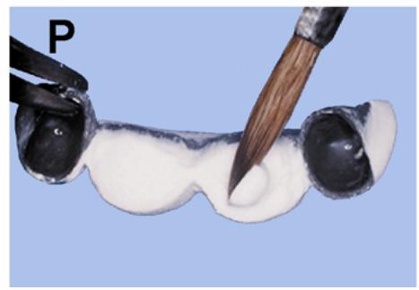
2.13.1.3. To apply the first coat of opaque, pick up a ball of porcelain on the brush and let it lightly contact the metal surface (Figure 2.20 -A). Move the brush down the metal and the opaque will follow it in a thin film. Continue to repeat this procedure until the entire porcelain-bearing are a is cov ered. It is important to work quickly so the opaque stays wet before it is condensed. Gently vibrate the opaque porcelain to smoothand condense the surface. NOTE: Allow the c asting to completely cool between porcelain applications. Al so, rewet the surface with distilled water before making subsequent additions.
2.13.2. Drying. Dry the opaque in front of an open furnace door or draw the moisture away with the tip of a facial tissue. Remove any opaque porcelain from the inside of the casting or on the nonporcelain-bearing areas.
2.13.3. Firing. Place the casting on the firing platform. Insert the crown into the furnace and start the vacuum pump. Set the temperature at 960 °C and the rate of temperature rise to 32 °C per minute. When the furnace reaches the right temperature, immediately remove the casting and let it bench cool. (IMPORTANT: Firing times and temperatures presented in this section are for VMK 68® porcelain used with Olympia® metal. They do not necessarily apply to other porcelain or ceramic alloys.)
2.13.3.1. Properly calibrate the furnace. If you have done so correctly, the fired opaque should have a matte finish or possibly a slight sheen similar to an eggshell surface. If the opaque has a glazed appearance, it was fired too high. An expert ceramist alwaysys fires porcelain to maturity, as identified by its appearance.
2.13.3.2. Apply the second opaque layer in a thin, even covering, eliminating all metal shadows. (Simply patching the gray areas would show through the veneer as a defect.) Fire the second layer the same as the first. The casting and opaque should now measure at least 0.5 mm in thickness, allowing 0.2 mm for the opaque layer.
2.13.4. Opaque Effects.
2.13.4.1. Intrinsic staining on firedopaque can he lp provide a basic color background to crowns. It should not be used to simulate spe cial effects such as che ck lines or decalcification marks. These special effects are better placed in the dentin and enamel porcelains. Most porcelain manufacturers supply special opaque powders to create opaque effects. Some of these coloredopaques are:
2.13.4.1.1. White—for lightening the standard opaque or adjusting the color at the incisal edge.
2.13.4.1.2. Gray—for gray shading both in the body and incisal areas.
2.13.4.1.3. Lilac Gray—same as paragraph 2.13.4.1.2.
2.13.4.1.4. Pink—for reddish discoloration spots and to produce a warm er tone in the standard opaques.
2.13.4.1.5. Brown—for increasing the brown color at the cervical area of opaque.
2.13.4.2. If the special opaque powders above are not available, try using other standard opaque powders or porcelain stains. The most practical use for opaque staining is at the cervical and incisal areas. Depending on the age of the patient, some cervical staining may be necessary. The effect may range in color from light brown to dark brown with varying amounts of other modifiers (orange and pink) mixed in.
2.13.4.3. For crowns that combine a body shade and a separate incisal shade, prepare two separate mixes of opaque porcelain and apply them as necessary (Figure 2.20-B). To lighten the incisal, mix white opaque with the chosen opaque shade or use lighter shade of opaque porcelain. To create more translucency at the incisal, mix blue, violet, or gray opaque with the chosen opaque porcelain.
¶ 2.14. Porcelain Application
2.14.1. Condensing Porcelain. The process of packing the particles together and removing the water is known as condensing. The methods used to condense the raw porcelain mass and your experience as a ceramist will determine the quality and the amount of shrinkage of the processed veneer:
2.14.1.1. Porcelain Shrinkage.
2.14.1.1.1. The amount of shrinkage is related to the porcelain powder’s particle size and shape. Porcelain powders contain several sizes of particles to reduce the amount of shrinkage. On the average, the volume shrinkage of porcelains is between 30 and 40 percent. This can be m isleading, though, because the amount of linear shrinka ge is only about 14 percent. Usually, you wouldonly be concerned with the linear shrink age because most of the shrinkage occurs in overall length.
2.14.1.1.2. Some porcelain powders are coarse grained, while others are fine grained. Fine grained porcelain has improved handling characteristics and lower volume shrinkage. How does the beginner judge shrinkage? Porcelain will always shrink toward the greatest bulk;
that is, toward the incisal and interproximal and at the suprabulge area (Figure 2.20-C). Pay careful attention to the line and point angles of the bulk porcelain buildup because they shrink the most.
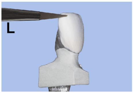
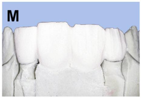
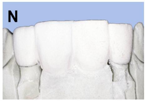
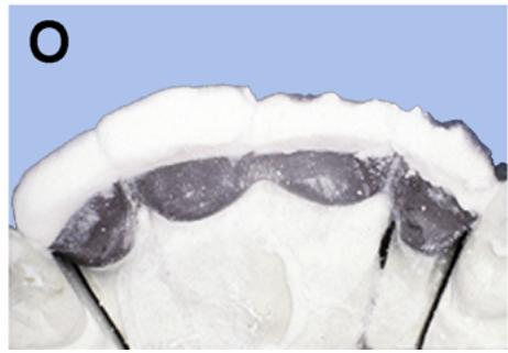
Figure 2.20. Layering Technique for Porcelain Application.
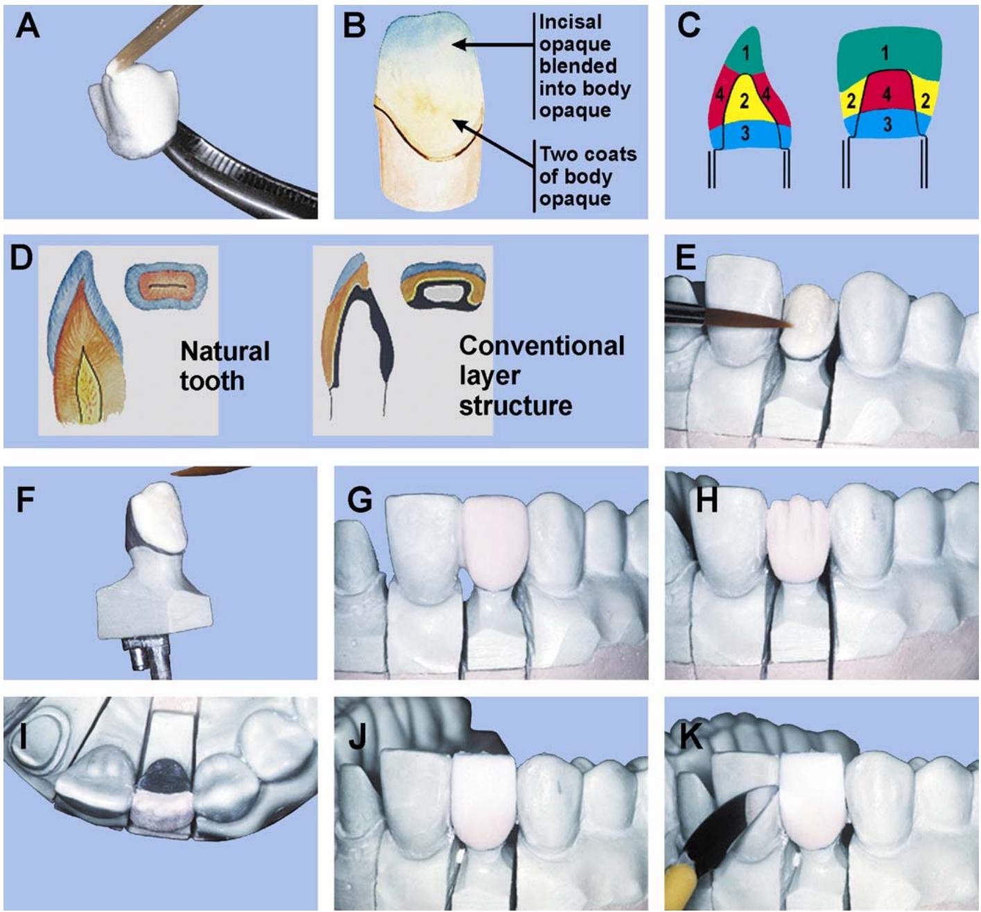
Figure 2.20. Continued.
natural_image
Close-up of a 3D-printed mechanical component with a tool applying force to its top surface (no visible text or symbols)
natural_image
Close-up of a dental model showing teethand jawbone structure (no text or symbols visible)
natural_image
Close-up of a dental model showing upper and lower teeth (no text or symbols visible)
natural_image
Close-up of a dental arch with visible teethand jawbone structure (no text or symbols)
natural_image
Close-up of a paintbrush applying white cream to a black ink bottle, with no visible text or symbols.
2.14.1.2. Methods of Condensing Porcelain.
2.14.1.2.1. Your ability to condense the porcelain will affect the amount of shrinkage and color of the fired porcelain. If the porcelain is not condensed enough, extra air spaces between particles will make the buildup shrink more and appear grayer. In contrast, porcelain that is well condensed will shrink very little, be exceptionally hard, and appearsaturated with color. It is not correct, however, to say that if a little condensation is good, a lot must be better. Hypothetically, if all the air spaces were removed, the porcelain would lose a great deal of its translucency, making the veneer look less vital.
2.14.1.2.2. Be sure to compare the shade of the restoration against its shade tab each time a buildup is fired. This will let you know how well your techniques are working. NEVER let the porcelain mass dry out during application. This is because dry porcelain can’t be condensed and it is hard torewet the buil dup once it dries out. Use the following four methods to condense porcelain:
2.14.1.2.2.1. Apply vibration by serrating or tapping withan instrument. This will eliminate large air bubbles or spaces. However, it is hard to control, and cracks may unintentionally be created in the buildup.
2.14.1.2.2.2. Perform capillary action by blotting from the lingual surface. In this way, the flow of moisture from the facial to the lingual will draw the particles closer together.
2.14.1.2.2.3. Perform pressure packing by smoothing with a spatula or pressing with a clean tissue.
2.14.1.2.2.4. Continue by whipping or brushing the surface with a large soft brush to fill in the surface voids and remove loose particles.
2.14.1.2.3. The net effect of these four methods increases the amount of surface tension within the buildup. Surface tension is the actual driving force that tightly binds the mass together. The entire condensation process can be described as being more molecular than mechanical.
2.14.2. Preparation. Make sure the cast is clean. Seal the surface contact areas with clear finger nail polish or cyanoacrylate glue to prevent moisture absorption and contamination of the porcelain. Using a wet brush, adapt a clean piece of tissue or rice paper over the ridge area. This will help keep porcelain from adhering to the cast and consequently aid in later removal of the buildup. Accurately seat the opaqued casting on its die.
2.14.3. Ready Materials. Measure out the dentin and enamel porcelains onto a glass slab or ceramic dish. Using a nylon mixing spatula or glass rod, mix the dentin powder with distilled water to a thick consistency. If the mix is too wet, blot the excess moisture awa y from the powder bed with a clean tissue. The condition of the powder bed is important because the air bubbles that rem ain in the mixture are a m ajor cause of porcelain failure. Also, you should be able to pick up small increments of the mix withan instrumentor brush. The mix should not be so thin that it would drip off the end of an instrument. If using color modifiers in the buildup, simplify their placement by dyeing the separate mixes with food coloring.
2.14.4. Layering Technique. There are as many different methods of porcelain application as there are ceramic authorities, and each one has an approach to reproducing natural teeth. Some authorities believe concessions have to be made for the optical differences between dental porcelain and natural enamel and dentin. Others contend de ntal porcelain should be layered the same as natural teeth. Either approach will y ield accep table results iforal conditions are favorable and the techniques are p roperly executed. Figure 2.20-D shows one approach used in building porcelain.
2.14.4.1. Applying Cervical Porcelain. Using a #6 sable hair brush, pick up a bead of cervical shade porcelain from the edge of the mix. Start at the cervical collar and flow the mix onto the opaque (Figure 2.20-E). Place each increment of porcelain with a gentle pushing and tapping action and absorb the ex cess water with a clean, dry tissue. Less cervical porcelain is used to simulate youth; more is used for middle-agedor elderly dentition.
2.14.4.2. Applying Opacious Dentin (Figure 2.20-F)
This material was developed with greater opacity for use in special shading situations. Opacious dentin is an intermediate shade porcelain, falling between the cervical and dentin shade porcelains. Use opacious dentin in place of cervical porcelain around the necks of t eeth to slo w light pen etration to the opaque layer. In the darkened and sha dowed interden tal areas, use it to create color and b rightness. Opacious dentin is espe cially helpful in corre cting the shad e difference between the pontic’s gingival portion with that of the re tainer’s. This difference is du e to the ab sence of opaque porcelain on the pontic’s internal surface layer and the dark reflect ion of the ging iva. Also use opacious dentin to create dentin effects, and, in very thin areas, to preventopaque showthrough.
2.14.4.3. Applying Dentin Porcelain (Figure 2.20-G)
2.14.4.3.1. Build the dentin porcelain drop by drop, using a brush or apply a greater amount of material using a spatula. Do not let the porcelain dry out, leaving large voids in the buildup. Gentle vibration of the cast will bring water to the surface where it can be blotted away. Avoid heavy vibration because it tends to make the porcelain slump; and it may also displace internal color modifiers.
2.14.4.3.2. Control slumping by pressing with a tissue on the lingual surface to draw the moisture through the porcelain. As water is withdrawn, the particles pack closer together due to surface tension. Slightly overbuild the porcelain mass to allow for shrinkage. At this point, the porcelain should be compact and moist.
2.14.4.3.3. A brush additive technique is suitable when placing porcelain modifiers and stains in the buildup as it progresses. On the other hand, the spatula technique is quicker and molding of the porcelain buildup is easier.
2.14.4.4. Cutback.
2.14.4.4.1. Note that not only does the cut back create space for the enamel porcelain, but it also forms the shape of the natural dentin with the dentin porcelain. The amount of dentin porcelain remaining depends on the shade selected and the firing shrinkage of the porcelain mass. There is also arelationship between the amount of dentin, en amel, and age. Young teeth have larger pulp chambers, more dentin, and less enamel than middle-aged teeth. The older the patient, the thicker the enamel layer becomes.
2.14.4.4.2. Using a bladed instrument, cut back the incisal third and proximal surfaces (Figure 2.20-H and -I)
Make two small grooves in the labial surface to simulate mamelons. Check the thickness of dentin porcelain covering the opaque withan instrument.
2.14.4.5. Applying Enamel Porcelain.
2.14.4.5.1. Mix the enamel porcelain a little thinner than the dentin porcelain. If the buildup is too dry, moisten it slightly before applying the enamel. Trying to add wet porcelain to an already dry buildup will cause entrapment of large air bubbles and areas of blotchy opacity.
2.14.4.5.2. Pick up a bead of enamel porcelain and apply it to the buildup. Continue to build up the incisal area until the original contour is established. The final buildup should extend 1 to 1.5 mm past the desired length (Figure 2.20-J). The enamel porcelain should blend well into the middlethirdor, for some shades, in to the gingival thirdof the tooth. This enamel overlay prevents a visible line of demarcation and creates an illusion of depth.
2.14.4.6. Completion. Using a thin blade, remove any porcelain from below the proximal contact area that might be in an undercut (Figure 2.20-K). Carefully remove the built up restoration from the cast. Remove any dirt particles that might be present because they will be visiblethrough the porcelain. Mois ten the mesial and distal c ontact areas of the buildup and apply clear porcelain to these areas (Figure 2.20-L). Smooth the completed buildup with a large soft brush to remove any loose particles. Clean excess porcelain away from the metal-ceramic junction, as well as porcelain particles inside the crown. Check the overall outline, contour, and detail of the buildup. Place the restoration to be firedon asagger tray.
2.14.5. Building FPDs.
2.14.5.1. Applying Porcelain. Follow the procedures in paragraphs 2.14.4.1 through 2.14.4.3 when applying porcelain.
2.14.5.2. Cutback. One technician might prefer to build each unit separately and cut back each one separately, trying to be as uniform as possible. Another technician will build the entire FPD in dentin porcelain, cut back the entire buildup, and then complete it with the application of enamel porcelain. Someone else would prefer to apply dentin porcelain and only cut back half of the buildup (Figure 2.20-M thro ugh -O). In this way, the enamel porcelain can be added to the cut back, using the adjoining buildup as a guide.
2.14.5.3. Contact Areas. Start by removing any porcelain that may be in an undercut. Remove the buildup by gently pushing up on the retainers. If any porcelain should break off, add it back or rebuild it. Now add clear porcelain to the mesial and distal contacts and dentin porcelain to the ridge area (Figure 2.20-P). Be careful in vibrating to avoid making the porcelain slump.
2.14.5.4. Firing Shrinkage.
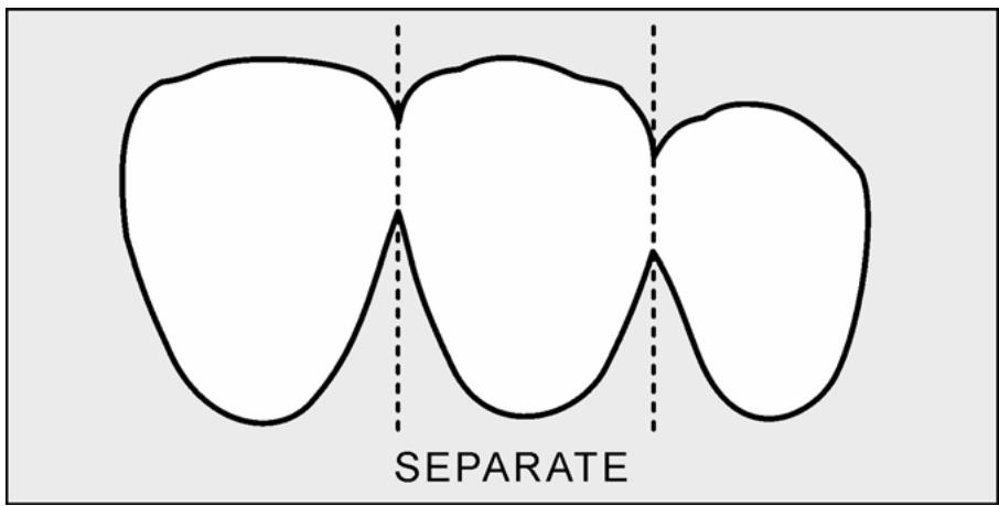
2.14.5.4.1. Firing shrinkage varies with the type of restoration. The porcelain on single unit crowns shrinks towards the center of the buildup. In the case of FPDs, firing shrinkage causes stress in the porcelain in the interproximal areas as it is drawn toward the center of each unit. S ome porcelain manufacturers recommend that each unit be separa ted by cutting through to the opaque, using ashar p instrument such as a razor blade (Figure 2.21). Do this torelieve stress and prevent cracking in the conventional buildup technique. The res ulting gap between the units is later filled in during the correction step.
Figure 2.21. Separating the Units.
text_image
SEPARATE
2.14.5.4.2. An alternative method to separating the units is to thoroughly precondense those areas where cracking is likely to occur. Using this method, first apply porcelain to the cervical and proximal areas and condense. Then, place the restoration on the working cast, and complete the porcelain buildup.
2.14.6. Building Porcelain Cusps (Figure 2.22)
There are two ways of controlling firing shrinkage. Either porcelain can be built in two or three bakes to full occlusion with the articulator closed or the porcelain can be built in one bake with the incisal pin opened one to two millimeters. Using the latter method, occlusion is restored and then refined during the contouring step (paragraph 2.15). Because the second method is simpler, its description is presented below:
2.14.6.1. Follow procedures in paragraphs 2.1 4.4.1 and 2.14.4.2 for applying cervical or opacious dentin porcelain.
2.14.6.2. Before building the dentin porcelain, apply a thin layer of cervical porcelain or orange-brown modifier near the occlusal fossae. Doing this will provide increased chroma in the depths of the occlusal grooves and fossae.
2.14.6.3. Apply dentin porcelain establishing cusp height and contour with the articulator completely closed (Figure 2.22-A)
2.14.6.4. To cut back the dentin porcelain, first remove 1 mm of porcelain from the occlusal table (Figure 2.22-B)
Reduce the buccal, lingual, and proximal surfaces by 1 mm and inspect the amount of cut back.
Figure 2.22. Building Porcelain Cusps.
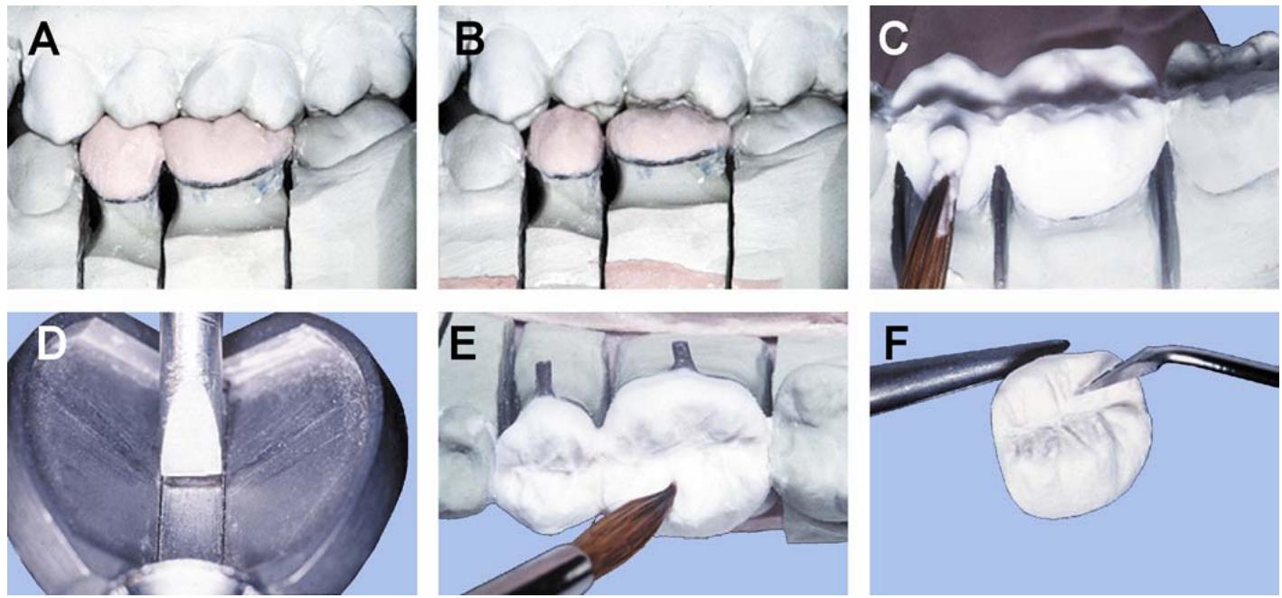
2.14.6.5. Apply the enamel porcelain to the buildup in wax-added fashion—first the functioning cusps and then the nonfunctioning ones. Apply enamel porcelain to the external surfaces of the buildup before establishing the internal inclinations of the cusps (Figure 2.22- C). Next add the marginal ridges and fill remaining occlus al voids. Condense the buildup at each stage. The completed enamel buildup should elevate the incisal pin 1 mm to compensate for shrinkage when fired (Figure 2.22-D).
2.14.6.6. After building with the restoration in occlusion, carve the primary grooves in the occlusal surface with a brush tip (Figure 2.22-E)
2.14.6.7. Remove the buildup and add to the proximal contacts. Thoroughly condense the buildup.
2.14.6.8. Because firing shrinkage can be predicted fairly accurately, carve the delicate secondary anatomy into the occlusal surface using a small bladed instrument (Figure 2.22-F)
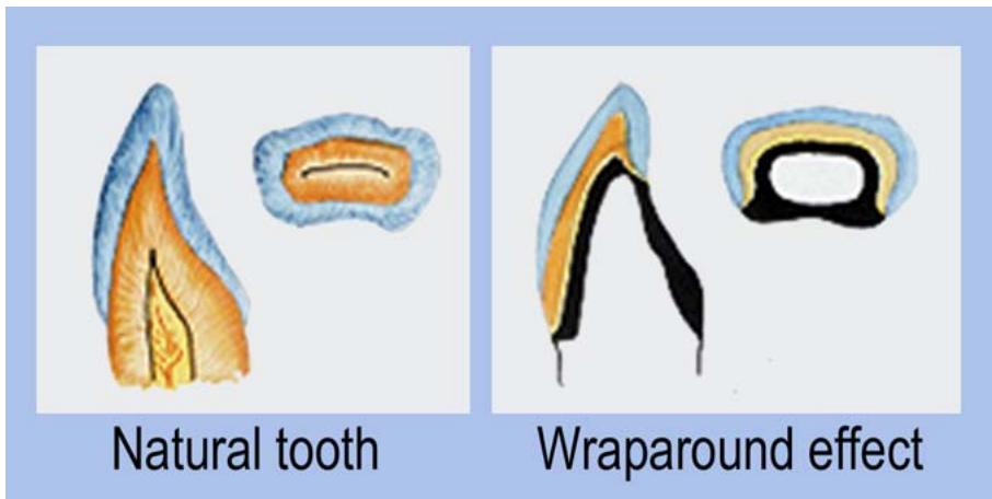
2.14.7. Modified Layering Technique. The clinical crown of a natural tooth is covered with enamel, creating a transition and depth of natural color. The conventional layering technique does not provide this “wraparound” effect of enamel. Use the modified layering technique as shown in Figure 2.23. It nearly copies natural dentition as follows:
2.14.7.1. Follow the basic technique for building porcelain layers as in paragraph 2.14.4.1 through 2.14.4.3.
2.14.7.2. Cut back the incisal third, proximal, and interproximal surfaces of the dentine layer. Remove about 1 mm of porcelain from each surface. Be sure to draw accurate guidelines on the surface before cut back. The amount of cut back on the proximal and interproximal surfaces is especially difficult to determine.
2.14.7.3. Apply enamel porcelain to the dentin layer. The enamel layer should be built up to resemble the contour of dentin porcelain prior to cut back. The enamel porcelain should extend slightly beyond the incisal edge to cover the dentin porcelain.
Figure 2.23. Wraparound Effectof Enamel.
text_image
Natural tooth
Wraparound effect
2.14.7.4. Apply clear porcelain to the entire facial surface. This will provide depth of color within the fired restoration. The completed buil dup should be 15 to 20 percent larger than the finished restoration. Because a clear porcelain la yer that is toothick makes the crown appear dark and gray, exercise care when constructing the dentin and enamel layer.
2.14.7.5. Once the facial surface is complete, cut back the lingual surface to make room for the next porcelain addition. Apply clear porcelain to the prepared lingual surface to complete the wraparound effect. Completion of the buildup is the same as the basic layering technique.
2.14.8. Porcelain Margin Technique. The ideal preparation for a collarless crown is a 90-degree shoulder preparation on the facial extending from one proximal surface to the other. This type of labial margin preparation allows you to butt the porcelain directly to the shoulder area. Alternate styles of margin preparation and casting design appear in Figure 2.24.
Figure 2.24. Margin Designs for Collarless Crowns.
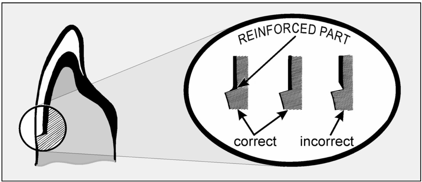
text_image
REINFORCED PART
correct
incorrect
2.14.8.1. Materials. In addition to the conventional materials, you will need:
2.14.8.1.1. Cyanoacrylate glue for sealing the surface of the die.
2.14.8.1.2. Porcelain separating medium (or mineral oil) to use as a release agent for the raw porcelain.
2.14.8.1.3. Shoulder porcelain for building the porcelain margin. Shoulder porcelain is gingival-shaded porcelain specially prepared to have a higher sintering temperature than other metal bonding porcelains. Many porcelain manufacturers have shoulder porcelain available for use with their systems.
2.14.8.1.4. Medium for mixing the shoulder porcelain. Disti lled water is preferred, but it is sometimes difficult to remove the casting and wet porcelain without fracturing the buildup. Some technicians prefer to mix the shoulder porcelain with the special liquid provided with phosphate bound investments. This special liqu id reacts with the porcelain, cau sing it to stiffen. Specially prepared waxes have also been developed to mix with porcelain. Mix 8 parts porcelain to 1 part wax by wei ght. Proponents of the wax technique say it works well in extremely difficult margin situations.
2.14.8.2. Procedures. It is difficult to achieve marginal accuracy with porcelain, d ue tofiring shrinkage. Therefore, porcelain margins must be built up two or three times until an acceptable fit is achieved.
2.14.8.2.1. Start by waxing the substructure as desi gned in Figure 2.25. Invest and complete the substructure in the usual manner. When finishing the casting, do not thin the metal at the labial shoulder because this could weaken the porcelain margin. Also ensure the proximal metal-ceramic junction meets the cervical margin abruptly at a 90-degree angleto reduce the chance of metal creep during firing. Opaque the casting.
Figure 2.25. Wax Patterns for Porcelain Margin Technique.
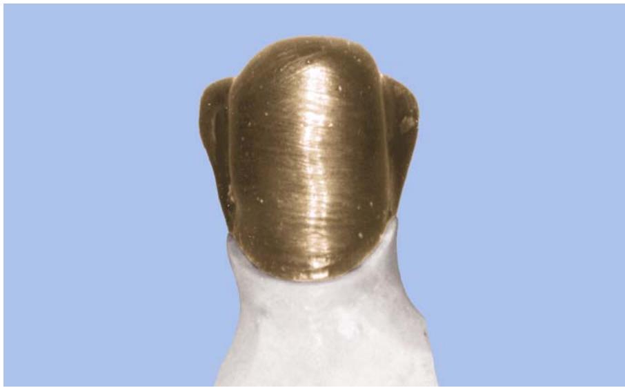
natural_image
Close-up of a metallic, textured object with a curved top and flared body, against a plain blue background (no text or symbols visible)
2.14.8.2.2. Apply a thin coat of cyanoacrylate glue to the facial shoulder area. After the glue has dried, apply a light coat of separating medium.
2.14.8.2.3. Make the buildup in two steps. First apply a bulk of shoulder porcelain to the shoulder area. Carefully remove the casting and dry the buildup (Figure 2.26). As the porcelain is drying, you may notice small dark areas on the surface. These dark areas are small amounts of organic matter in the porcelain. In this instance, the entire cervical margin will appear black because of the separator. Don’t fire the porcelain until this area has completely dried or porosity will result in the processed porcelain.
Figure 2.26. Applying Shoulder Porcelain in the Porcelain Margin Technique.
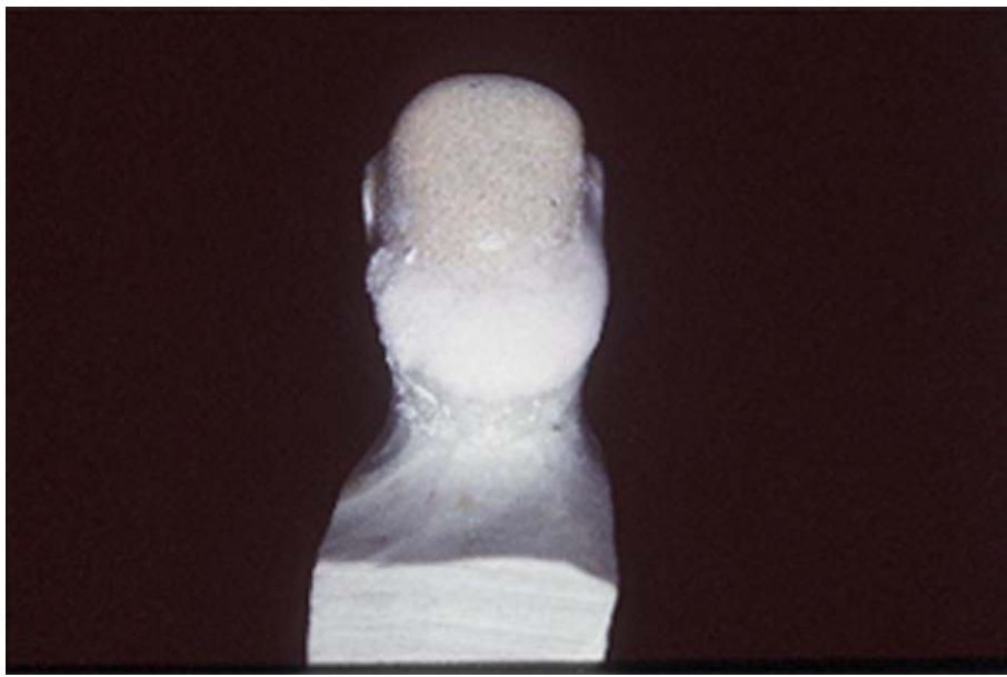
natural_image
Close-up of a white, textured sculpture head against a dark background (no text or symbols visible)
2.14.8.2.4. Once the porcelain has been fired, add more shoulder porcelain to the marginal area to fill the gap and repeat the firing process. When the crown is again cool, contour the processed porcelain to finalize the facial margin. The remainder of the construction sequence follows the normal metal-ceramic technique.
2.14.9. Dentin Effects (Figure 2.27)
You can create a multitude of dentin effects in the dentin porcelain with porcelain powders called effect powders or modifiers. Porcelain stains may also be used, but their intensity is hard to control.
2.14.9.1. Altered Shades. Basic hu e and chroma changes can be made to a small area of the dentin porcelain or to the entire facial surface area of the veneer.
2.14.9.1.1. To increase chroma in a small area, start by building the porcelain to full contour and then carve away the porcelain in the affected area (Figure 2.27-A). Next, apply the effect powder to that area, tapering the porcelain onto the sides (Figures 2.27-B and -C). The dentist may request that the entire gingival shade be altered, changing the hue of the veneer.
2.14.9.1.2. To make a predominantly gray shade appear yellower, first cover the opaque with a layer of porcelain that has a yellow hue (Figure 2.27-D and -E). Follow this layer with a layer of porcelain that has a gray hue. You can decipher the dominant hue for a given shade porcelain by looking at the shade guide. Whatever the desired effect, you can make it by combining different porcelain shades.
2.14.9.2. Dentin Mamelons.
2.14.9.2.1. In many cases, dentin mamelons (Figure 2.27-F) originate during the development of the teeth, appearing as three finger-like extensions of the dentine separating the incisal edge.
2.14.9.2.2. To simulate this effect. the porcelain is built to full contour and two grooves are cut into the incisal third (Figure 2.27-G). Then a small amount of colorless porcelain is placed in each groove (Figure 2.27-H). The net effect will be to increase the tran slucency in these areas.
2.14.9.3. Discolored Fillings.
2.14.9.3.1. Discolored fillings (Figure 2.27-I) are composite or plastic restorative materials that have discolored. They usually appear opaque like and have brown discoloration marking their boundaries.
2.14.9.3.2. Build the porcelain to full contour and hollow out the area to be filled (Figure 2.27-J)
L ightly coat the walls of the cavity with yellow-brown stain. Then fill the cavity with a core of opaque porcelain followed by clear porcelain (Figure 2.27-K).
Figure 2.27. Dentin Effects in Dental Porcelain.
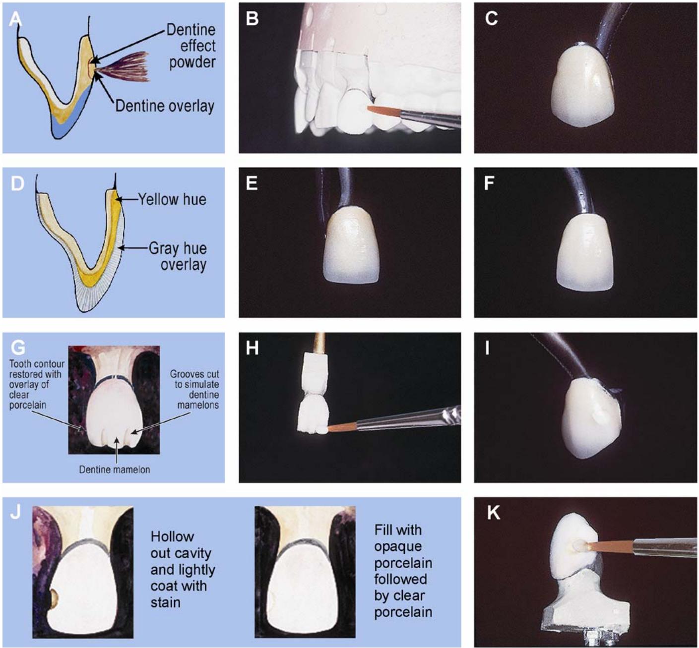
2.14.10. Incisal Effects (Figure 2.28)
These effects range from fine check lines to strong orange hues. The effect of subtle shading of the incisal will drastically affect the appearance of the veneer.
2.14.10.1. Enamel Check Lines (Figure 2.28-A)
2.14.10.1.1. To adequately simulate a natural check line or crack, reproduce it in depth. The reason for this is these defects in the enamel are difficult to reproduce with surface stains.
Figure 2.28. Incisal Effects in Dental Porcelain.
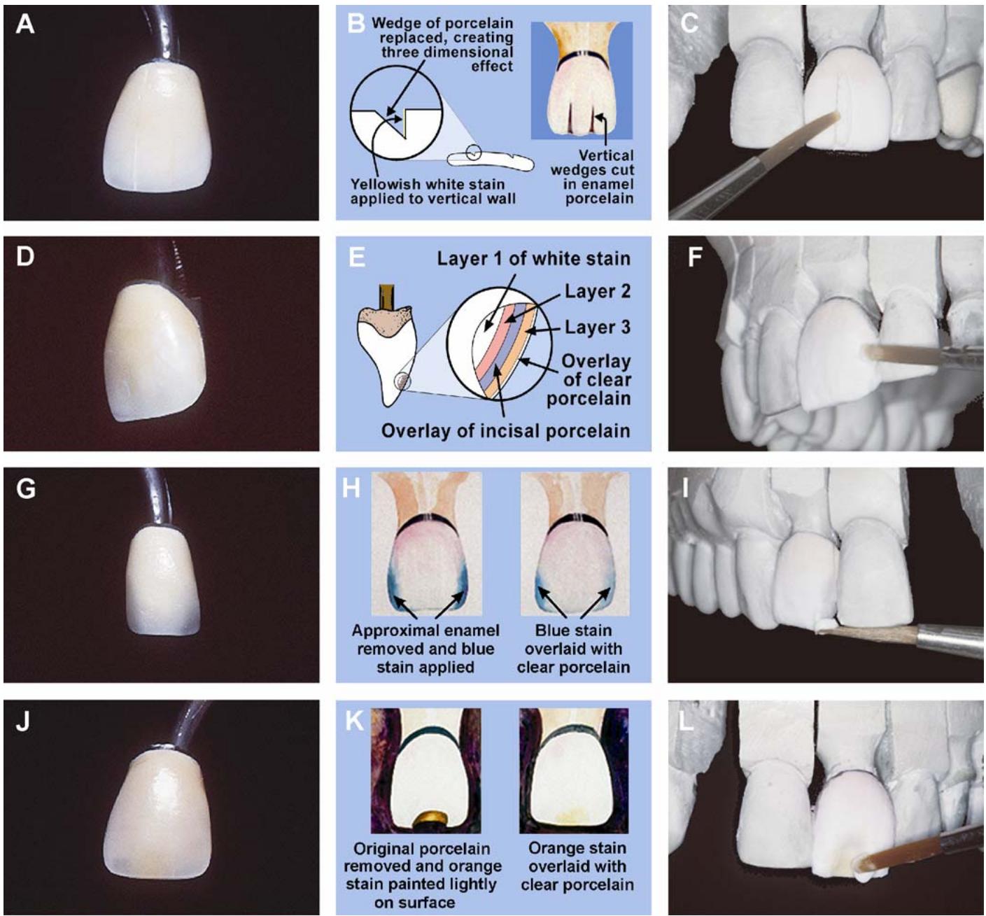
2.14.10.1.2. Build up the entire crown, including enamel porcelain. Cut a V-shape wedge in the incisal third and put it aside to be replaced later (Figure 2.28-B). Now, with one light stroke, apply yellow-white stain to the vertical wall and remove any excess from the facial surface with a clean brush. Do not work the stain into the porcelain. Gently replace the wedge slice you saved earlier and seal the cut by lightly tapping the cast on the bench top (Figure 2.28-C). Failure to seal the cut could lead to fissure cracks during firing.
2.14.10.1.3. This effect is also accomplished by creating and staining a ve rtical wall during initial layering of the incisal porcelain. This eliminates difficulties associated with replacing and sealing the V-shaped wedge. However, great care must be taken to ensure the stains are not disturbed while completing the incisal buildup.
2.14.10.2. Hypocalcification.
2.14.10.2.1. Note that white hypocalcified areas are also hard to reproduce with surface stains. They often appear as a series of white dots that do not look like natural hypocalcification (Figure 2.28-D). This effect is better treated using white modifiers or effect powders in the porcelain buildup. White effects are better created if they are applied in two or three layers (Figure 2.28-E).
2.14.10.2.2. Use a fine brush tip to pick up just the right quantity of white powder and gently rub it into place. Then cover the white powder with enamel porcelain and repeat the process (Figure 2-27-F).
2.14.10.3. Blue Translucency.
2.14.10.3.1. Remember, natural teeth often appear more translucent (Figure 2.28-G) at the mesial and distal incisal edges.
2.14.10.3.2. To create this effect, remove a small amount of incisal porcelain from the mesial and distal proximal surfaces (Figure 2.28-H)
Apply blue stain to these areas with a light stroke and overlay them with clear porcelain (Figure 2.28-I). Be careful not to remove too much incisal porcelain because this will cause the blue effect to be lost in the graying of incisal by the clear porcelain.
2.14.10.4. Incisal Orange Hue.
2.14.10.4.1. Notice how this effect appears as an orange hue at the incisal, just short of the incisal edge (Figure 2.28-J)
The enamel outlines the orange effect like a halo.
2.14.10.4.2. To reproduce this effect, first scoop out a section of enamel porcelain from the facial surface of the incisal edge (Figure 2.28-K)
Next, apply orange stain to the prepared area. Follow that withan application of clear porcelain (Figure 2.28-L).
¶ 2.15. First Dentin-Enamel Firing
2.15.1. Drying. Let the buildup dry fully to keep from releasing steam and causing large sections of the veneer to crack. The amount of drying time depends on the amount of moisture, which can be judged by the density of the mass and elapsed time from initial application. Also, setting the entrance temperature too high will fracture the porcelain. Dry and preheat gradually by moving the restoration closer to the hot zone of the furnace muffle in stages. The entire drying, preheating, and inserting process usually takes 3 to 6 minutes, depending on the number of units to be fired. The entrance temperature should stay at 600 °C during this entire process.
2.15.2. Firing Sequence. Center the restoration in the muffle or on the firing platform and close the muffle door. Seal the vacuum chamber and start the vacuum pump. Do not increase the temperature until you get a full vacuum of 26 to 29 inches of mercury. Set the amperage control for a rate of rise of 32 °C per minute and set the temperature control for the maturing pointof the porcelain at 940 °C. When the restoration reaches 940 °C,, release the vacuum and remove the fired porcelain immediately. Let the restoration cool completely before handling it. Most porcelain furnaces in use today can be pre-programmed tofollow the porcelain manufacturer’s recommendations for firing their porcelain.
¶ Section 2E — Anatomical Contouring
¶ 2.16. Shaping the Sintered Porcelain Veneer
2.16.1. Use abrasives designed for finishing and polishing porcelain surfaces to shape the veneer. Each type abrasive has a specific function (Figure 2.29). Certain rubber wheels and points are used to smoothand polish. Bulk-reducing wheels can be used for most of the overall contour. These abrasive wheels remove porcelain quickly and wear at about the same rate as the porcelain, making them ideal for “roughing out” the restoration’s form.
Figure 2.29. Contouring Metal-Ceramic Restorations.
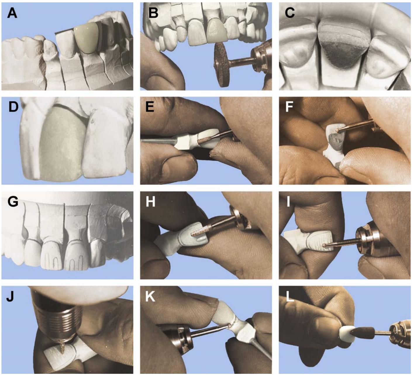
2.16.2. Various shaped diamond-cutting instruments can also be used for shaping and characterizing the surface. When they are new, these devices cut very quickly and should be used cautiously. An alternative to the “diamonds” would be mounted stones and points.
2.16.3. Avoid using abrasives that have been used on other materials. Each time you must refire the restoration, be sure to remove the porcelain’s glaze first by lightly air abrading the surface with aluminum oxide and then clean the restoration using an ultrasonic and distilled water. (Review Chapter 1, Section 1H, Esthetics, before continuing.)
¶ 2.17. Establishing the Overall Contour
2.17.1. Initially, inspect the inside of the crown for sintered (fired) porcelain particles or other interferences that might keep the crown from seating. Seat the crown on its die and verify its marginal accuracy. So metimes the metal may distort u pon sinterin g, lifting away from the preparation’s shoulder (known as metal creep). If possible, adjust each proximal contact separately until the crown is completely seatedon the cast (Figu re 2.29-A). When thr ough making adjustments, the crown should be in light contact and smooth. The proximal surface can either be rubbered smooth or lightly finished with asandpaper disc.
2.17.2. Next, restore the functional occlusion of the crown according to the dentist’s prescription (that is, unilateral balance or mutually protected occlusion). Restore MI first; then adjust the restoration in working, balancing, and protrusive excursions. When adjusting the crown in excursive movements, be careful n ot to remove too much of the crown’s length. When the occlusion is correct, you can then adjust the length of the incisal edge until it matches the adjacent tooth (Figure 2.29-B). Also consider the linguoincisal line angle of the incisal edge. This angle may be steep or shallow, showing visible signs of wear (wear facets). Precision grinding of the incisal edge and embrasure form is an absolute must.
2.17.3. Using a bulk-reducing wheel, grind away enough porcelain from the facial surface until the curvature matches the teeth being duplicated. The mesiodistal and distofacial lin e angles are especially important because almost all ante rior tee thexhibit a “rounding in” effect at their distofacial surface. From incisal and proximal views (Figures 2.29-C and -D), insp ect the facial contour and alignmentof the incisal edge.
2.17.4. Frequently check the thickness of the veneer with a metal gauge, especially in the incisal third area. If the thickness measures less than 1.2 mm, chances are the opaque may be noticeablethrough the enamel porcelain. This “ light spot” of opaque is hard to hide, using extrinsic stains. An alternative to this approach is to shape the restoration in a protruded fashion, but esthetics of the restoration might be compromised.
2.17.5. Shape the cervical thirdof the veneer so the contour is continuous with the cervical collar (Figure 2.29-E)
If the crown is collarless, alsorefine the porcelain shoulder margin at this time. Normally, the height of contour of the crown (suprabulge area) will correspond to the adjacent teeth.
2.17.6. Smooth the entire facial surface while ensuring all the line angles are correctly positioned. Inspect the shape of the labial surface by viewing it from several as pects. You should be able to line up the facial surface of the restoration with the adjac ent to oth. This exact symm etry is not always the goal, but use it as a guide.
2.17.7. Once you have defined the overa ll facial contour, start shaping the lingual surfaces with a small diamond wheel or ball diamond (Figure 2.29-F). The crown should have a definite lingual fossa withincisal edges correspond ing to the adjacent teeth. Check again to en sure the crown functions properly with the movements of the articulator in excursive positions.
¶ 2.18. Charactering the Veneer Surface
2.18.1. Study the working cast or diagnostic aid for surface details. Most teeth have a satin finish, and only the high spots, such as ridge and point angles, will be shiny. Often signs of wear or abrasion may change the character of older teeth. These teeth may appearsmoother, and some facial anatomy (horizontal grooves, development lobes) may be absent. Only a close inspection of the adjacent teeth of a diagnostic cast will determine the exact method of characterization.
2.18.2. With a sharp pencil, trace out the ridge and point angles (Figure 2.29-G) and make a final check of the facial contour. Use a small diamond point or diamond wheel to make the developmental grooves. Scribe a fine groove. Then, if necessary, widen and deepen it by gently moving the diamond from side to side (Figure 2.29-H).
2.18.3. Observe how num erous small transverse lines may sometimes cover the facial surface of teeth. The surface may vary greatly from having deep irregular grooves to appearing almost smooth. Use a small diamond ball to create these striation s (Figure 2. 29-I). Fin er lines can be drawn across the surface as shown in Figure 2.29-J.
2.18.4. Note that the patient’s tissue will often recede, exposing the cervix of the tooth. Reproduce this cervix on the veneer’s surface or the crown will look too long. Overcontour in the cervical area can also lead to chronic gingivitis. Use a small round diamond to simulate the cervix of the crown (Figure 2.29-K). Your goal in this critical area is to reproduce the original contours or to match the adjacent teeth. Lightly touch and polish all high spots with a rubber wheel to simulate natural wear in the mouth.
¶ 2.19. Establishing Occlusal Surfaces
It is difficult to establish occlusal contact in porcelain as successfully as with metal. The optimum type of occlusion for a porcelain occlusal is mutually protected occlusion because the forces of mastication are mostly vertical. Also, when possible, cusp-to-fossa tooth orientations are preferred.
2.19.1. Contacts. Avoid contacton marginal ridges where porcelain is easily fractured. Do not widen occlusal tables or leave sharp edges on porcelain cusps because breakage is more likely.
2.19.2. Redefine Occlusal Anatomy. Grinding posterior occlusal surfaces requ ires great skill. The objective is to highlight detailed anatom y made whe n the porcelain was first applied, not create it. The grinding stones and diamonds should, therefore, be used with a very light action. Some suggested finishing device s and their uses can be seen in Figure 2.30. Fissures should be finished with points, and suppl emental grooves and fossae with small round diamonds. Be sure to remove all porcelain thatoverlaps the metal before glazing. During final polishing, any fired porcelain lefton the metal will be very hard to remove.
¶ 2.20. Shaping FPDs
As the number of units increases, so does the level of difficulty. Finishing an FPD will require more time and patienc e. Before you actually sta rt, think about and planyour approach to contouring each restoration. It may be helpful to sc ribe a pencil lin e showing the boundaries of each individual unit.
2.20.1. The initial steps of seating the restoration are the same as for a single unit. Adjusting the contact areas will be easier if you can remove one of the adjacent teeth or ridge area from the cast. The process of functionally contouring begins by restoring MI, then working and balancing excursions, and finally the protrusive excursion. A diagnostic cast is almost a necessity in determining the length of a larger anterior FPD. Without it, estim ate the length according to the anterior guidance present and the proportionate length of the remaining anterior teeth.
Figure 2.30. Types of Diamonds Used To Carve Porcelain Occlusals.
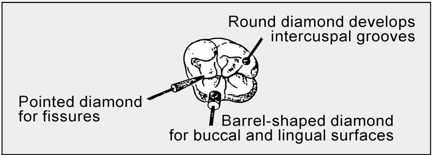
text_image
Round diamond develops intercuspal grooves
Pointed diamond for fissures
Barrel-shaped diamond for buccal and lingual surfaces
2.20.2. One of the more difficult steps involves shaping the interproximals. During the porcelain application step, many ceram ists cut through the porcelain to the opaque, separating the teeth. When the restoration is processed, the porcelain shrinks away from these areas. The task now is to remove all sharp edges by light grinding with a diamond-coated discand then later adding porcelain to the interproxi mal areas and refiring the restoration. But first, its best to shape the remaining bulk of porcelain to establish the ove rall contour and prevent needless repeated porcelain additions. Then, lightly air-abrade and clean the restoratio n in an ultrasonic before adding porcelain in the interproximals andother deficient areas. NOTE: Ensure interproximal spaces are precisely positioned and contoured to allow only minimal finishing.
2.20.3. Separation betw een the units must be finely divided and deep enough so the teeth will appear natural (Figure 2.31)
This division should appear V-sh aped and not like a groove separating the individual units. It takes p atience to shape teet h to look natural and not like “cutouts” bonded to a metal backing. Use a diamond-coated ultra-thin separating disc to divide the units. Exercise care not to grind through the porcelain, exposing the opa que layer or underlying metal.
Figure 2.31. Separation Between Units of Anterior FPDs.
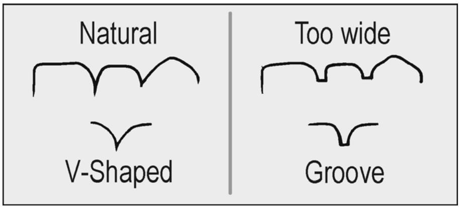
text_image
Natural
V-Shaped
Too wide
Groove
¶ 2.21. Secondor Corrective Dentin-Enamel Firing
To add porcelain, first remove the glaze and clean the restoration. Then apply the same porcelain powders originally used during the initial app lication to make the addition. Be sure to add enough porcelain to allow for r econtouring. Process the porcelain addition under vacuum and at a slightly lower temperature.
¶ 2.22. Repairing Porcelain (Low-Fusing, Air-Fired)
2.22.1. Another way to correct post-co mpletion contour or repair porcelain veneers is with repair porcelain (for example, correction powder)
These porcelains will bond to glazed or unglazed surfaces, but, an unglazed surface is preferred. Repair porcelain fusing temperatures are considerably below that of the standard veneer porcelains. Consequently, they are sometimes mixed withstandard powders to lower the fusing temperature of the mix.
2.22.2. Uses for repair porcelain include filling imperfections such as bubbles or cracks, adding onto the occlusal where it does not contact the opposing bite properly, adding to interproximal contact areas, adding to pontics that are short of contacting the tissue, and correcting crown contour near the gingiva. These additions can be carried out at the glaze step without risking the vacuum cycle and possibly causing the veneer porcelain to bubble.
2.22.3. While some repair porcelains such as Ceramco® 1600 Add-On Porcelain are supplied in as many shades as standard porcelain s, others are designed to be mixed with the regu lar dentine and enamel powders. Because materials are widely diffe rent and repair situations vary, consult the manufacturer’s directions when using repair porcelains.
¶ Section 2F — Staining
¶ 2.23. Shade Modification and Characterization
Extrinsic staining involves applying porcelain stains to the surface of a porcelain restoration and then processing the stains, usually during the glazing sequence. When the stains are fired, they actually become part of the porcelain, covered by a thin, transparent glaze layer. Surface stains are highly pigmented objects that absorb some wavelengths of light and reflect others. As such, when they’re used in heavy concentrations, they tend to mask the surface of the porcelain, reducing the translucency and vitality of the product. The stains should be mixed to a consistency that is neither too dry nor too wet. They should flow oneasily (evenly and smoothly), but stay in place and not run. The surface on which the stains are placed should be clean and dry and, of course, the glaze must be removed. Review Section 2B on color and shade.
2.23.1. Shade Alteration. Any changes in shade should be minor and, if possible, limited only to corrections between adjacent shade tabs. It would be better to remake the veneer rather than make a major correction to the shade.
2.23.1.1. Surface Glaze. Apply a liquid glaze medium to the porcelain surface to simulate a glazed surface. The liquid medium will restore the surface luster and allow a good appraisal of color. Do not use saliva or water for this purpose. Compare the crown and shade tab, using principles discussed in paragraph 2.4. Evaluate the color of the restoration to determine where the change is needed—hue, chroma, or value.
2.23.1.2. Chroma Adjustments. To increase the chroma, simply add the stain of the same dominant hue as the crown until the intensity is correct. To decrease the chroma, add the compliment of the dominant hue. If the shade is bright yellow, adding violet will neutralize it. This also lowers the value but, hopefully, it will not be so drastic as to cause a mismatch. NOTE: Usually, the processed porcelain veneer is of higher value than required (depending on the ceramist’s ability to apply porcelain). If the processed porcelain veneer always appears darker, it is because the porcelain is not being condensed properly.
2.23.1.3. Hue Adjustments. To change the hue of a restoration, refer to the color wheel (Figure 2.32-A). Only two hue m odifications are necessary because natural teeth are located in the yellow to orange range. To move a yellow hue to an orange hue, add a pink stain. (The stain
represented by redon the color wh eel is actually a pink.) T o change a orange hue to yellow, add a yellow stain.
2.23.1.4. Value Adjustment.
2.23.1.4.1. Lowering the value can be done very eas ily by adding the com plementary color. If the dominant hue is orange, add blue. If the dominant hue is yellow, add violet. Because most teeth have a yellow hue, the violet stain is used more often, especially in the incisa l third. Adding violet to the incisal area has the effect of apparent translucency. If the crown being modified has a dominant hue of orange, use a blue stain instead.
2.23.1.4.2. Another very powerful modifier used to lower value is brow n stain. Brown is a low value shade of red, orange, or yellow. A small amount of brown applied to the surface will increase chroma and lower value.
Figure 2.32. Extrinsic Staining of Metal-Ceramic Crowns.
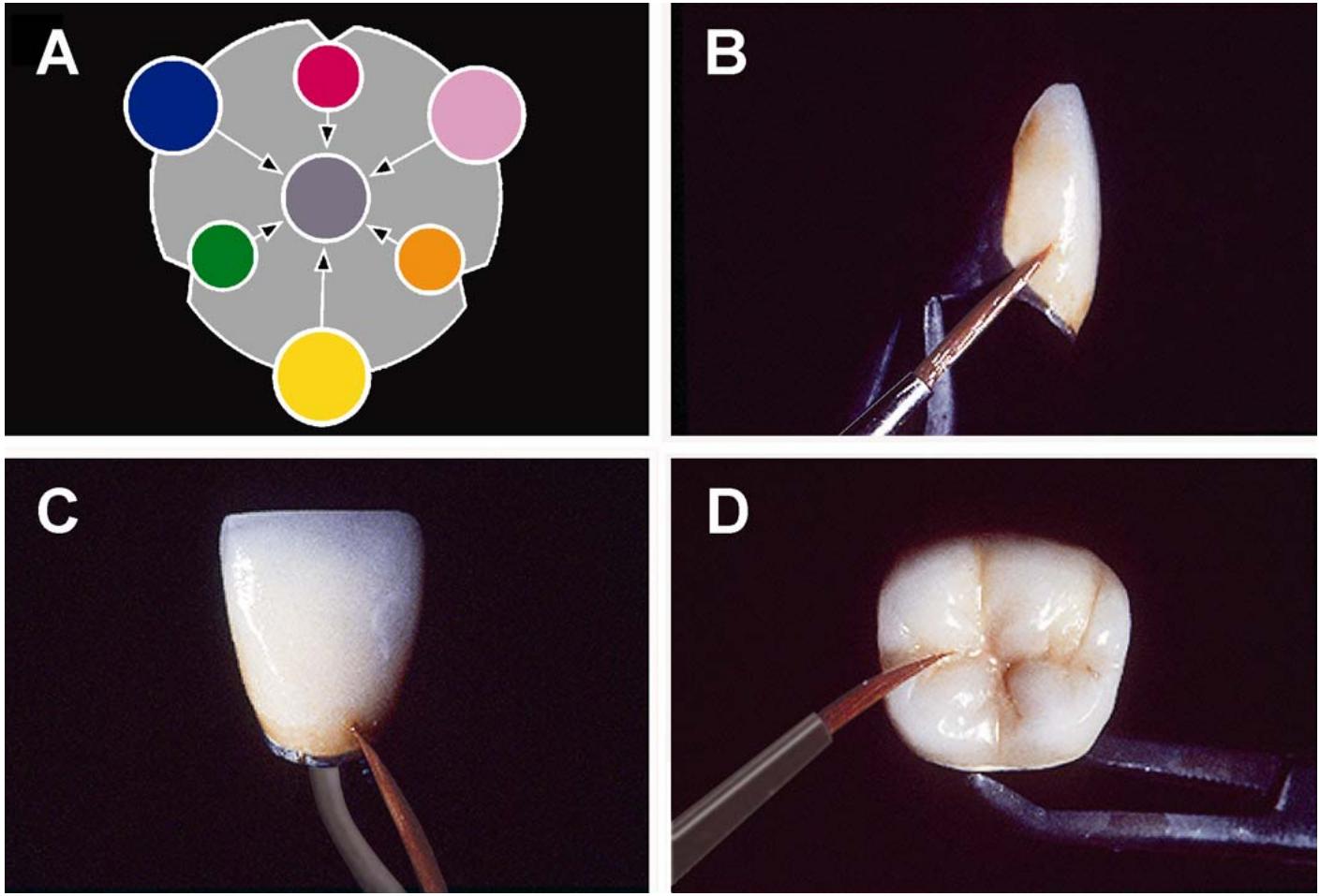
2.23.1.4.3. Raising the value of a restoration is next to im possible. The only successful way toraise value is by adding astain of higher value, which may change the hue, increase chroma, and alsoraise the value. Sometimes a small amount of white stain can increase the value, but it is not a go od choice of modifiers, because it is very opaque. NOTE: If at any time, the actual hue of the stain can be seen ra ther than the neutral gray desired, remove the stain with a tissue and repeat the procedure.
2.23.2. Characterization (Figures 2.32-B through -D)
The desired effect of external characterization is similar to the placement of internal modifiers. However, withinternal modifiers, the characterization can be seen in d epth. The goal of every ceramist is to produce a restoration so natural it prevents detection when seated in the patient’s mouth. Therefore, any characterization should not be the focal point, but it should blend into the entire com position with balance and harmony:
2.23.2.1. Proximal Staining.
2.23.2.1.1. Every tooth will appear to have some degree of proximal staining. The intensity and color of the staining may vary with the age and lifestyles of the patient. A young patient may have very little proximal staining compared to an older patient. The same comparison can be made between a coffee drinker and nondrinker.
2.23.2.1.2. To simulate proximal stain, apply a mixture of orange and brown stain that compliments the patient’s age and tooth color to this area, extending facially just beyond the contact area, but not covering the facial surface itself (Figure 2.32-B). You can also apply this orange-brown mixture to the interproximal connector areas of an FPD to enhance the apparent separation of the units. Be sure to remove any excess stain from the facial surface. For a fairly young patient, use a gray mixture instead. For the most part, the mesial and distal surfaces of a FPD unit should be treated the same way as an individual crown.
2.23.2.2. Cervical Staining. The cervical areas of a tooth reflect the pink coloration of the gingiva and may also be stained. This effect may vary from a light pinkish-orange color to an orange-brown color. Cervical staining is present on most shade guid e tabs and will have a bearing on the overall shade of the restoration. Cervical staining is often used to simulate the root portion of a tooth. This is especially true of periodontally involved teethand exceptionally long pontic. To remedy the problem, an orange-brown mixture its applied to the prepared area to accentuate the cementoenamel junction and make the restoration look shorter (Figure 2.32-C).
2.23.2.3. Enamel Cracks.
2.23.2.3.1. The enamel crack is hard to simulate with surface stains. T o give an appearance of depth, the enamel crack simulation should have both a highlight and ashadow. This can be done by applying a mixture of white and yellow stain (4 to 1 ratio) in a thin line.
2.23.2.3.2. The excess stain is removed by a method called painting off (Figure 2.33)
Use a clean brush to narrow the width of the line and to apply asecond gray stain line distally to the first, simulating the shadow. Narrow this second line until just a hintof shadow rem ains. The combination of these two should give the illusion of a fracture (Figure 2.28-A).
Figure 2.33. Painting-Off Technique.
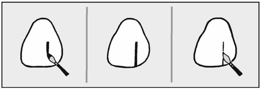
natural_image
Three simple line drawings of tree leaves with shading, no text or symbols present
2.23.2.3.3. Sometimes the enamel crack lines beco me discolored with food, tobacco, or other stains. If this happens, replace the white-yellow mixture with one of orange-brown and apply with a small amount of orange stain alo ng either s ide of the first line to create the shadow.
2.23.2.4. Hypocalcifications. These areas result from the removal of calcium from the enamel and appear as white blotches or even white lines (Figure 2.28-D). To create this effect, use white stain mixed with liquid medium to a fairly heavy consistency. Although this stain is quite opaque, it is sometimes difficult to apply in the opacity desired. If the stain applied is toothick it will actually create lu mps on the surface. The desired effect shou ld appear much the same after firing as it does when the stain is applied.
2.23.2.5. Resin Restorations (Figure 2.27-I)
Sometimes it is necessary to place a metal-ceramic crown in the mouth of a patient who has many anterior composite restorations. A flawless restoration would look outof place in such an environment. To simulate aresin filling, the proper color of an orange-b rown mixture (also white, if need ed) is selected and applied to the desired area. Then, the first app lication is o utlined with a slight bitof brown stain. The outline should be narrowed to a thin marginal line.
2.23.2.6. Anatomy. The occlusal anatom y of posterior teethand lingual anatom y of anteriors should also show degrees of characterizatio n to define surface detail and break up the monotony of the basic shade. The concern, how ever, is to avoid the overuse of stains. Different ratios of orange and brown are used, depending on the anatomy. A darker stain would normally be applied to a defect (such as a pit) rather than to a groove or fissure. On occlusal surfaces, the stain is randomly applied with a fine-tipped brush (Figure 2.32-D). The lines should appear as mere suggestions of grooves, rather than being heavily accented. Marginal ridges can be made to seemmore translucent by adding violet st ain. Cusp tips are highlig hted with white sta in. Lingual anatomy may also be accentuated in much the same way.
¶ Section 2G — Glazing
¶ 2.24. Overview
Glazed porcelain surfaces have been described as being impervious to mouth fluids and biologically compatible with oral tissues. The glaze itself is a for mation of a thin transparent g lass. The amount of glaze on the surface determines its appearance. A low glaze appears as a slight sheen with no loss of surface detail. A medium glaze appears with some rounding of fine detail. A high glaze appears glossy (high ly reflective, smooth) with a greater loss of surface detail and for m. A medium glaze is usually preferred for its beauty and long-lasting quality. Also, in the patient’s mouth, some of the surface detail may become filled with saliva and, therefore, go unnoticed.
¶ 2.25. Autogenous Method
2.25.1. This method is usually done in conjunction withextrinsic staining and is preferred by many for its durability, sim plicity, and beau ty. After the restoration is proces sed, the stains become a part of the thin transparent glass that covers the restoration.
2.25.2. Twofactors that are used to cont rol the for mation of the glass are time and temperature. Either variable can be increasedor decreased to obtain the desired amount of glaze. For example, a crown sintered to 920 oC may require holding at that temperature for a period of 2 or 3 minutes. The same crown fired to 940 oC may only require holding 1 or 2 minutes. It is always easier and safer to inc rease the ho lding time than to increase the temperature. You might accidentally cause the porcelain to coalesce or devi trify. If the porcelain co alesces, it will need to be recontoured. If the porcelain devitrifies, it may not glaze, in which case you must startover.
2.25.3. After the extrinsic staining is complete, place the restoration on a firing tray and then on the firing table to dry. Set the firing temperature at the lowest end of the manufacturer’s recommendation or 20 °C below the last known firing temperature for that restoration. A typical setting would be 920 °C for 2 to 3 minutes. Air-fire the restoration, using the proper time and temperature controls. Remove the restoration and visually inspect the glaze. If the restoration is underfired, immediately replace it in the furnace and raise the temperature another 10 °C and hold the restoration at that temperature for 30 seconds to 1 minute. When you observe the desired amount of glaze, remove the restoration immediately and let it completely cool.
¶ 2.26. Overglaze Method
2.26.1. Some uses of this technique are toreglaze denture teeth, facings, or prefabricated pontics after they have been adjusted; reglaze a ceramic restoration that has been adjusted; and ensure a glazed surface covers a ceramic restoration that may have been difficult to glaze. An autogenou s glaze is superior to an overglaze so avoid the routine use of an overglaze.
2.26.2. Mix the overglaze powder with the liquid medium until it will string from the spatula when lifted from the mix. Apply the mixture in one direction, using a small brush. Keep the mix even and remove any excess or puddling. Dry the overglaze in front of an open furnace as if it were astain. Correctly applied glaze material will appear as an even white layer after drying. Air fire the restoration to a temperature of approximately 860 °C. Immediately remove the restoration and let cool.
¶ Section 2H — Soldering
¶ 2.27. Presolder
This technique joins the units of a metal-ceramic FPD before porcelain is applied (Figure 2.34). Presoldering metal-ceramic units requires a solder with a much higher fusion temperature (about 1090 °C) than Type III gold solders. The solder joint must be able to withstand the porcelain firing temperatures. Be sure the presolder you are using is matched to the ceramic alloy in its composition and color.
2.27.1. Preparing the Units.
2.27.1.1. The principles and theories of presolde ring differ somewhat from those used for conventional soldering. The strongest presolder joints are those that have been prepared so they need the least amount of solder. Trying to bridge a large gap, especially if the presolder has been overheated, will result in a weak joint. The proper amount of solder gap width for presoldering is 0.1 mm. The area of the sold er joint must also be rubbered smooth before making the matrix.
2.27.1.2. One method of separating the units of a FPD is to make a diagonal cut through the pontic. The cut can be made with aseparating disc through the casting or by making a diagonal cut with a warm razor blade through the wax pontic (Figure 2.34-A). This way, the solder joint will be long and thin, resulting in a much stronge r joint. Ideally, the con nectors should be cast metal (for strength) so they are not as good a location for a presolder joint.
2.27.2. Soldering Matrix. Seat the units on the cast and secure them with sticky wax. Join the units together with a high quality fast-setting material such as Dura Lay® or Zap-It® (Figure 2.34-B). Once the material has set and the units are removed from the cast, check the tissue side of the joint for voids. Fill any voids with more material.
2.27.3. Investing the Assembly.
2.27.3.1. Use a special high-heat solder investmentor phosphate-bonded casting investment. If casting investment is used, mix with distilled water insteadof the special liquid to limit expansion to an absolute minimum. Mix the investment thick; a thin mix can weaken the investment, causing it to crack at high temperatures.
2.27.3.2. Place the mix inside each retainer, usin g a bladed instrument (Figure 2.34-C)
Next, place a patty of the mix on a paper towel and invert the assembly onto the patty (Figure 2.34-D). The towel absorbs moisture, which helps to control slumping. Make sure the margins are covered and the metal is supported. However, do not bury the castings because it would make soldering more difficult because of poor heat transfer to the castings.
2.27.3.3. The assembly should rest gently on the investment mound withas much metal exposed as possible so the heat can be applied quickly and evenly withoutoverheating the assembly. Let the investment bench set for at least 45 minutes and then trim the investment base to these dimensions: 10 to 15 mm thick, and 3 mm beyond the castings (Figure 2.34-E)
2.27.4. Preheating the Assembly. Burn off the Dura Lay® or Zap-It® and preheat the solder assembly before applying the soldering flame. One burnout method suggests placing the assembly in a cold furnace, raising the temperature to 1300 °F, and then letting itheat soak for about 5 to 10 minutes.
2.27.5. Soldering the Units.
2.27.5.1. Us e a gas-oxygen torch with a special soldering tip to melt the solder. Adjust the oxygen pressure to 6 pounds and set the gas pressure between 6 and 8 pounds. Light the torch and check the flame. Adjust the flame until the inner cone is about 15 mm long. If the torch is adjusted right, there should be little or no hissing.
2.27.5.2. Remove the assembly from the oven and place iton a tripod. Immediately direct the flame around the base of the investment toraise the temperature. Then di rect the flame to the castings until they show a slight orange color. Holding the torch in one hand and the presolder in the other, place the end of the strip onto the joint. Now, as you direct the flame onto the joint area, the solder will melt and flow down into the joint (Figure 2.34-F).
2.27.5.3. Remove the solder strip, but keep a brush flame on the assembly. Move the flame to the reverse side of the assembly and draw the solder through the joint. So lder will always flow to the hottest areas.
2.27.5.4. Let the investment bench cool completely before you remove the castings (Figure 2.34-G)
On multiple units, never solder more than two joints at a time.
¶ 2.28. Postsolder Technique
This technique involves furnace soldering metal-ceramic restorations that have already had porcelain applied to them (Figure 2.35). Occasionally, a Type III gold alloy retainer must be soldered to the remaining part of a metal-ceramic FPD. Another use includes splinting two metal-ceramic crowns to strengthen weak abutment teeth. Finally, this technique may be used torepair the metal part of a metal-ceramic restoration.
2.28.1. Preparing the Units.
2.28.1.1. Assembling the units is much the same as for Type III gold alloy. Because you will use low-fusing solder, y ou can make the solder assembly withany solder investment. A solder gap width of 0.250 mm between the metal surfaces is suggested, but the porcelain veneers should be as close to each other as possible without contacting.
2.28.1.2. Lightly rubber all surfaces to be soldered, seat the units on the abutment teeth, and flow wax into the prepared area. Use asteel bur and sticky wax to hold the units together.
Remove the solder relation and flow ivory wax over any porcelain surface that would contact investment (Figure 2.35-A). This will keep the solder investment from contacting and fusing with the veneer (Figure 2.36).
Figure 2.34. Presolder Technique.
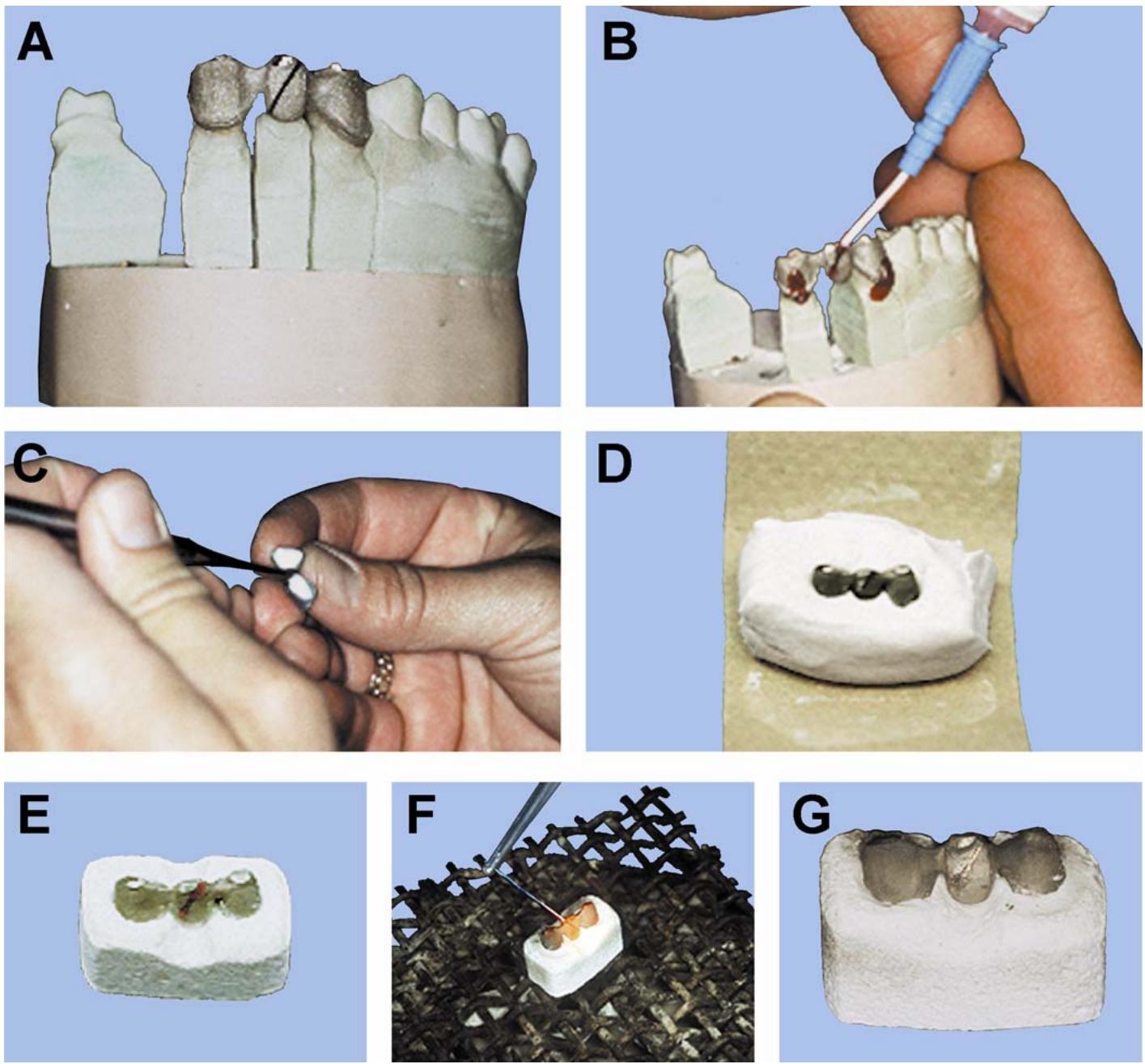
2.28.2. Investing the Assembly. Mix a small amount of soldering investment and construct the assembly as described in paragraph 1.75.2.2. Carve a V-shaped notch on the lingual to ensure adequate access to the solder joint. Flush out the wax with boiling water. Place the invested units on the firing table of a porcelain furnace to warm slowly for 10 minutes. Then move closer to the muffle and warm it for 5 more minutes.
Figure 2.35. Postsolder Technique.
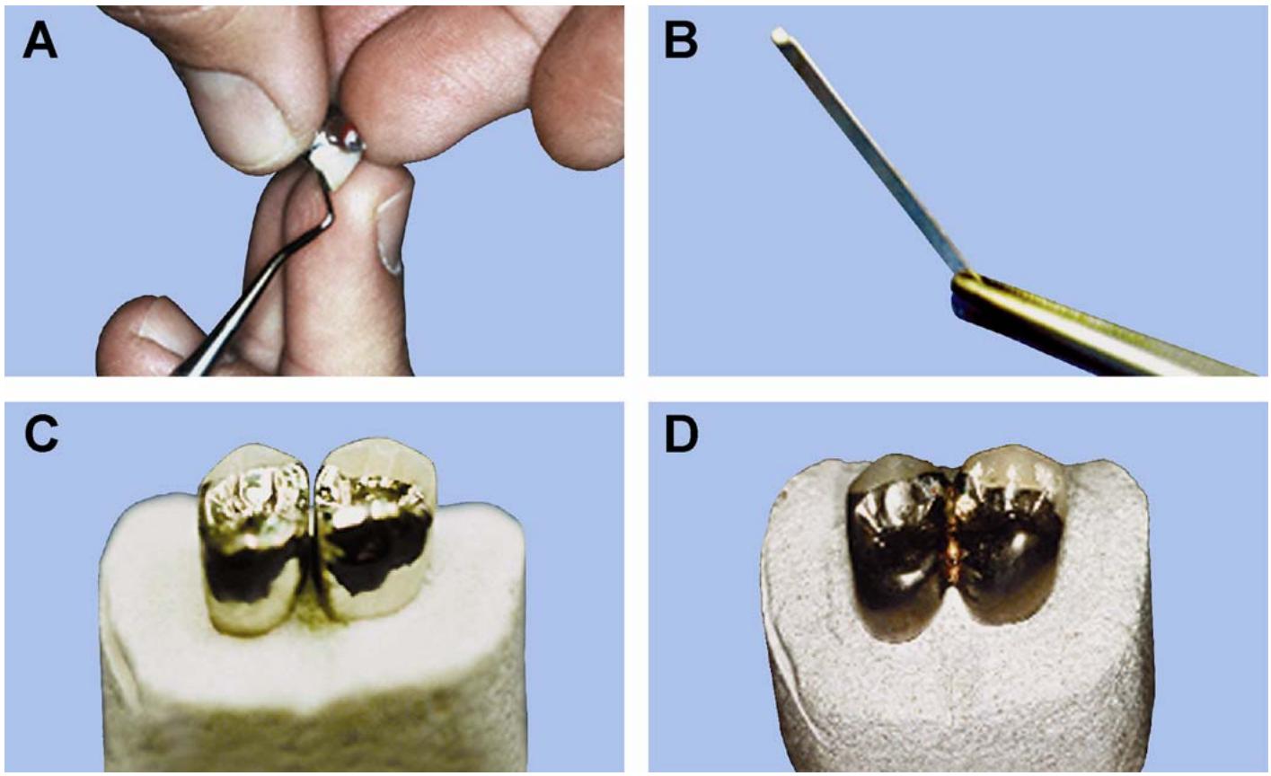
Figure 2.36. Investing a Metal-Ceramic Restoration (Cross-Section).
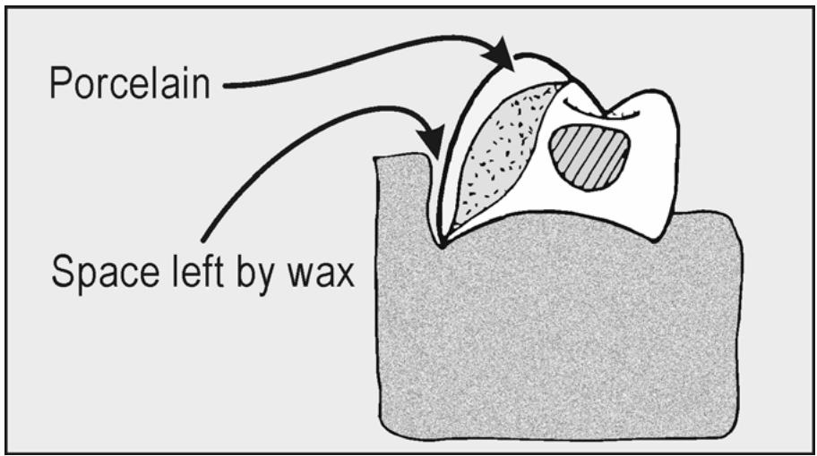
text_image
Porcelain
Space left by wax
2.28.3. Soldering the Units.
2.28.3.1. Hold a strip of low-fusing solder over a bunsen burner until a small ball of solder forms (Figure 2.35-B)
Cutoff the ball of solder, leaving a small tail long enough to touch the investment patty. Apply flux to the solder joint. Apply antiflux to the occlus al surface to confine the solder flow. Position the ball of solder with the tail extending down (Figure 2.35 -C).
2.28.3.2. Place the assembly in the furnace and start the vacuum pump to reduce the amount of oxide that would normally form in the solder joint. (A porcelain furnace with a viewing glass is best because you can watch the solder melt.)
2.28.3.3. Set the furnace to 870 °C (slightly above the fusing temperature of the solder) and wait for the solder to melt. The actual temperature the solder flows may vary with the solder used. Start to check for solder flow when the oven temperature reaches 815 °C. Release the vacuum and remove the assembly as soon as the solder wets the joint (Figure 2.35-D). If the solder is overheated, you’ll have porosity and an embrittled joint. The solder joint should extend far enough gingivally to recontour and still maintain adequate strength.
2.28.4. Repairing Exposed Metal Surfaces. After the porcelain has been applied, make any metal repairs by the postsolder technique, using the rules for low-fusing alloys. Furnace soldering is preferredover torch soldering for this purpose because it is more controlled and does not subject the porcelain to drastically changing temperatures. Rem ember to position the restoration in the solder investment to take full advantage of solder flow. This would be the case in soldering a hole or contact area.
¶ Section 2I — Resin-Bonded FPDs (Maryland Bridge)
¶ 2.29. Design Factors
The two primary considerations are to establish a distinct path of insertion to allow for proper seating and resistance to dislodgment and to maximize the bonding surface of the retainers for strength and retention. The design of the retainers consists of four parts:
2.29.1. Proximal Segment. The dentist prepares the abutment teeth by removing enamel from the proximal suprabulge and undercut areas to increase the bonding surface. This enamel shaping extends just past the proximal line angle, allowing the retainer to grasp the abutment and provide bracing for the framework (Figure 2.37). The proximal wrap limits facial-lingual movementof the retainer during function. The dentist may also cut small subtle grooves in the interproximal parallel to the path of insertion to resist displacement.
Figure 2.37. Resin-Bonded FPD Design.
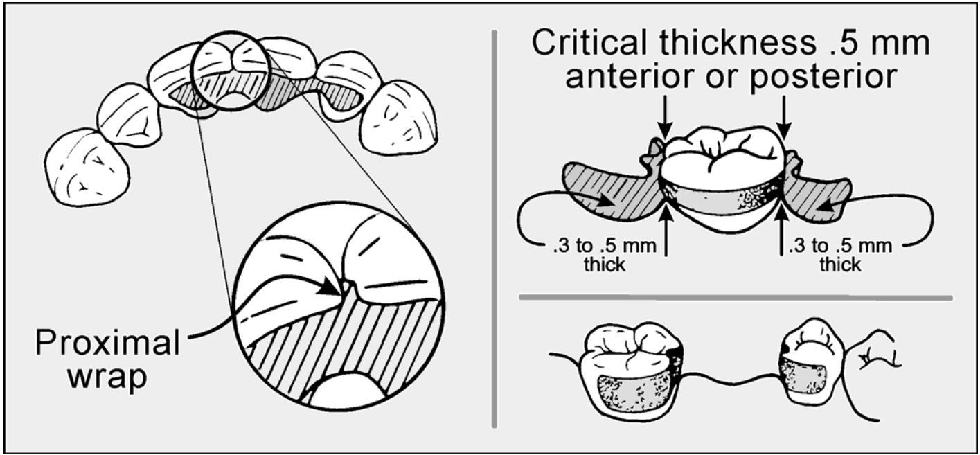
text_image
Proximal
wrap
Critical thickness.5 mm
anterior or posterior.3 to.5 mm
thick.3 to.5 mm
thick
2.29.2. Lingual Segment. The design goal in the lingual segm ent is to create as large a bonding surface as possible without creating periodontal problems, excursion problems, or plaque traps. Therefore, it is necessary that the framework ends 1 mm away from the gingival tissue and has a knife-edge finish. The metal thickness of the framework should range from 0.3 mm to 0.6 mm. The minimum thickness passing over a marginal ridge is 0.6 mm. This thickness increases with the transition into the connector areas.
2.29.3. Occlusal Rests. Preparations for occlusal rest seats for resin-bonded retainers are shallower, narrower, and have straighter “locking” walls than occlusal rest seats for RPDs. Rest seats are usually about 1.5 to 2.0 mm in diameter and 1.0 mm in depth.
2.29.4. Seating Stops. The design may include incisal seating tabs to provide positive orientation of the restoration during cementation or to stabilize mobileteeth (Figure 2.38). These stops greatly enhance positive seating during the short time period available for bonding. Afterward, the tabs are cutoff and smoothed. Many dentists object to the tabs because, in some instances, the y interfere with making occlusal adjustments. An alternative method involves the use of dimples or delicate horizontal slots prepared in the lingual enamel of anterior teeth.
Figure 2.38. Seating Stops for Resin-Bonded FPDs.
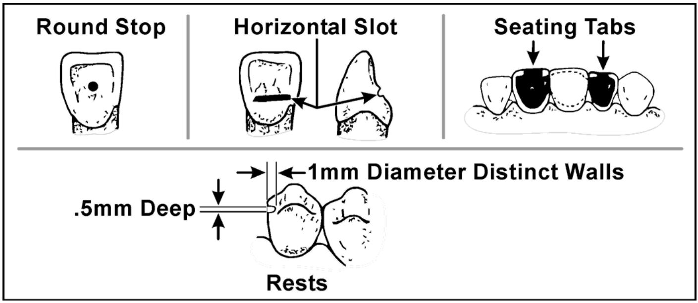
¶ 2.30. Framework Fabrication
There are two methods of producing frameworks for resin-bonded FPDs. The first involves the use of arefractory cast, where the pattern is waxed directly to the refractory cast, sprued and invested, and cast to the refractory cast. In the second method, the pattern is waxed directly on the master cast, sprued, pulledoff the master cast, invested, and then cast into metal. These two methods are as follows:
2.30.1. Refractory Cast Method. A refractory cast can be made in the following two ways: (1) by initially pouring the impression in stone and repouring it asecond time in refractory material, or (2) by duplicating master casts and pouring arefractory cast. The first way requires less material and is less time consuming.
2.30.1.1. Mixing and Pouring the Refractory Material. Mix and pour the refractory material into the impression in the usual manner. Adhere to the manufacturer’s recommended liquid to powder ratios and mix under vacuum for 60 to 90 seconds. Mechanically spatulate the mix
under vacuum for 60 to 90 seconds. Pour only the involved portion of the impression and a tooth to either side. Let bench set for 45 minutes before removing the cast. NOTE: Full-arch refractory casts are requiredonly when the refractory casts are articulated.
2.30.1.2. Surveying the Cast. Routinely survey refractory casts to establish the height of contour on abutment teeth. This indicates undercut areas and discourages overwaxing of the pattern and later corrections to seat the framework on the master cast. Do not block out these undercut areas, even when duplicating casts. To do so would eliminate proximal contours needed to properly shape the gingival half of the pattern. Outline the extent of the framework with a wax pencil.
2.30.1.3. Waxing the Pattern. Follow the design factors given in paragraph 2.29 when waxing frameworks for resin-bonded FPDs. The dimensions given are for the finished casting. The pattern thickness may be increased slightly to allow for finishing.
2.30.1.3.1. Mount the master casts on an articulator in the prescribed manner. Wax the ponticsubstructure on the master castor modify a preformed plastic substructure pontic form to fit the edentulous space. Ensure adequate space is allowed for porcelain coverage of the pontic. By beginning the wax-up on the master cast, you are able to check the occlusion without having to articulate the refractory cast. The pontic is later transferred to the refractory cast for pattern completion.
2.30.1.3.2. Attach the pontic to the refractory and flow a uniform layer of wax over all areas within the design. Keep in mind the minimum thickness of metal needed for strength and add about a tenth of a millimeter thickness for finishing. Smooth the pattern and prepare to invest.
2.30.1.4. Trimming the Refractory Cast. Trim the base of the cast prior to investment in order to fit the appropriate size casting ring. Leave an investment base at least 10 mm thick for strength. After the investment is set, any portion of the base sticking out from the ring can be removed. The pattern is now ready for spruing and investing.
2.30.1.5. Spruing and Investing the Pattern. Attach asprue former to the wax pattern and apply a wetting agent. Line the casting ring with a thick layer of petrolatum; use no other ring liner. Use distilled water insteadof the special liquid and vacuum spatulate the mix as before. The reason for these modifications is torestrict expansion and thereby reduce the possibility of mold separation and casting fins. Let the invested ring bench set for at least 60 minutes. Proceed to burnout and casting (paragraphs 2.9 and 2.10).
2.30.2. Pulled Pattern Method (Figure 2.39)
2.30.2.1. Articulate the master cast. Use a wax pencil to mark the margin outline on the cast (Figure 2.39-A). Apply aresin to stone separator to the cast.
2.30.2.2. Using a pattern resin build up the wing and proximal portions of the retainers (Figure 2.39-B)
Pattern resin is used to minimize pattern distortion. Do not extend the resin beyond the margin outline and maintain an even thickness. After the resin has cured carefully remove the resin wings, cut back any margin overextensions, and reduce thick areas (Figure 2.39-C). Replace the completed wings on the cast.
2.30.2.3. Slowly add resin from the proximal of each retainer towards the opposite retainer. Allow the resin to cure before contact is made between the two retainers. This minimizes the amount of distortion between the resin retainers and the abutments. An alternate method is to use a plastic sprue cut to fit between the retainers without applying pressure to the retainers.
Connectone side of the plastic sprue and let the resin cu re (Figure 2.39-D). Connect the remaining space between the retainers and the plastic sprue then let the resin cu re (Figure 2.39-E). After the resin substructure is fully cured, evaluate it for accuracy and fit.
2.30.2.4. Wax the pontic to full contour. Cutback the pontic following the guidelines for metal-ceramic cut backs (Figure 2.39-F). Check margins and make any necessary corrections. Another method is to remove.5 to 1 mm of resin from the margins and readapt wax to margin areas.
Figure 2.39. Pulled Pattern Technique for a Resin-Bonded FPD.
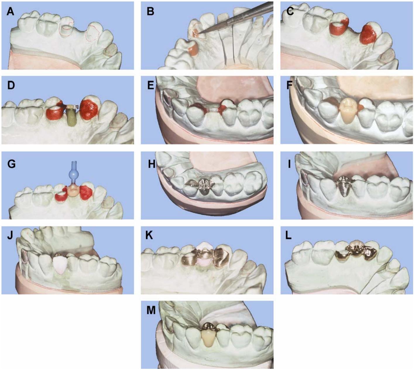
2.30.3. Sprue and Invest. Sprue and investing is the same as the guidance given in paragraphs 2.7 and 2.8. Take care not to warp the retainers during these procedures (Figure 2.39-G).
2.30.4. Burnout and Casting. Place the ring in a cold furnace, raise the temperature slowly (90 minutes or more) to 1500 °F and heat soak for 1 hour. Follow the guidance in Chapter 3 of this
volume for casting of base metal alloys. NOTE: Base metal alloys, nickel-chrome or chrome-cobalt, are generally used for the resin-bonded technique. As such, meticulous handling of these alloys must be observed each step of the way for successful porcelain bonding. It is important that no more than 25 to 30 percent recast alloy be used with this technique.
2.30.5. Finishing. Follow normal procedures for sprue removal, fitting the framework to the master cast, and finishing (Figure 2.39-H and -I). Be prepared for the dentist to request a framework try-in of an extensive restoration to check casting fit. Do not finish or rubber wheel surfaces that are to be bonded to the tooth preparations.
2.30.6. Porcelain Application. There are difficulties associated with applying porcelain to this style framework (Figure 2.39-J through -M). The distinct path of insertion can make removing the raw porcelain buildup difficult. If a section of the mass breaks away, hopefully it can hopefully be replaced or fresh porcelain added with the framework off the cast. Also, support of the framework during firing procedures must be aided by using metal or ceramic posts with grooves in them. The proximal wrap causes the pontic to be slightly wider than the edentulous space, and shaping the pontic can be an esthetic compromise without showing opaque or metal. A detailed description of this critical area appears in Figure 2.37. Due to these difficulties, expect the dentist to request a try-in after final bisque bake and before staining, glazing, and polishing.
¶ 2.31. Bonding Preparation
Have ALL aspects of the restoration completed prior to this step; adjustments and polishing can lead to contamination of the prepared bonding surface.
2.31.1. Base Metal Alloys. With the adventof new cements in dentistry today, it is no longer ® required to acid-etch the bonding surfaces of the retainers. Adhesive cem ents, such as Panavia 21, Kuraray Co., and C&B Metabond, require air abrading the retainer’s bonding surface with 30 to 50 micron aluminum oxide. Air abrade at 80 to 100 psifor 2 to 3 seconds to produce a matte finish. Then wash the restoration under running water for 1 minute and place it in the ultrasonic cleaner for 2 to 3 minutes in a neutral detergent solution.
2.31.2. Noble Alloys. When noble alloys are cast for the substructure, tin-plating is used to prepare the retainers for bonding. This is accomplished by means of an electro-plating process, using one of several commercially available plating machines. First sandblast with aluminum oxide and then deposit a layer of tin approximately 0.5 microns thick, using manufacturer’s recommended procedures and plating times. Follow up with washing and ultrasonic cleaning the same as with base metals.
2.31.3. Storing. After preparing the retainers for bonding, keep the prostheses in a dry, contamination-free place.
DentalTechnology.org is dedicated to preserving, teaching, and advancing the craft of dental technology.
This resource is made possible by Russellville Dental Lab, a full-service dental laboratory in Russellville, Kentucky, serving clinicians across the USA for more than 70 years.