¶ Chapter 6 — DENTAL IMPLANTS
Reference Edition
This chapter is part of the Air Force Dental Laboratory Manual (2005) – Digitally Restored Edition.
This edition preserves the original publication while correcting OCR errors, restoring formatting, reconstructing damaged tables where necessary, and improving digital readability.
The technical content has not been rewritten, modernized, expanded, or altered.
It is provided as a professional reference. Modern instructional material is published separately throughout DentalTechnology.org.
¶ 6.1. Introduction
6.1.1. The ability to restore a patient’s function and esthetics is the ultimate goal in dentistry. Implant technology has brought a whole new dimension to achieving that goal. Since the mid-sixties, implant technology has developed into what is now a viable alternative to conventional prosthodontics. Patients that once had few or no options can now have function and esthetics restored with implant technology.
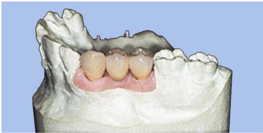
6.1.2. A dental implant is a prosthetic device implanted within the bone to provide retention and support for fixed or removable appliances (Figure 6.1). Implants can be used to replace single teeth, multiple teeth, or as retainers for dentures. There are many different implant systems currently in use.
6.1.3. This chapter provides an introduction to the principles, basic terminology, and procedures to fabricate dental implants. When fabricating dental implant prostheses, be sure to closely follow the manufacturer’s directions for the system being used to maximize the chances of success.
Figure 6.1. Implant Prosthesis.
natural_image
3D dental model showing upper and lower dentition with visible teeth and gum tissue (no text or labels)
¶ 6.2. Standard Components for Implant Systems
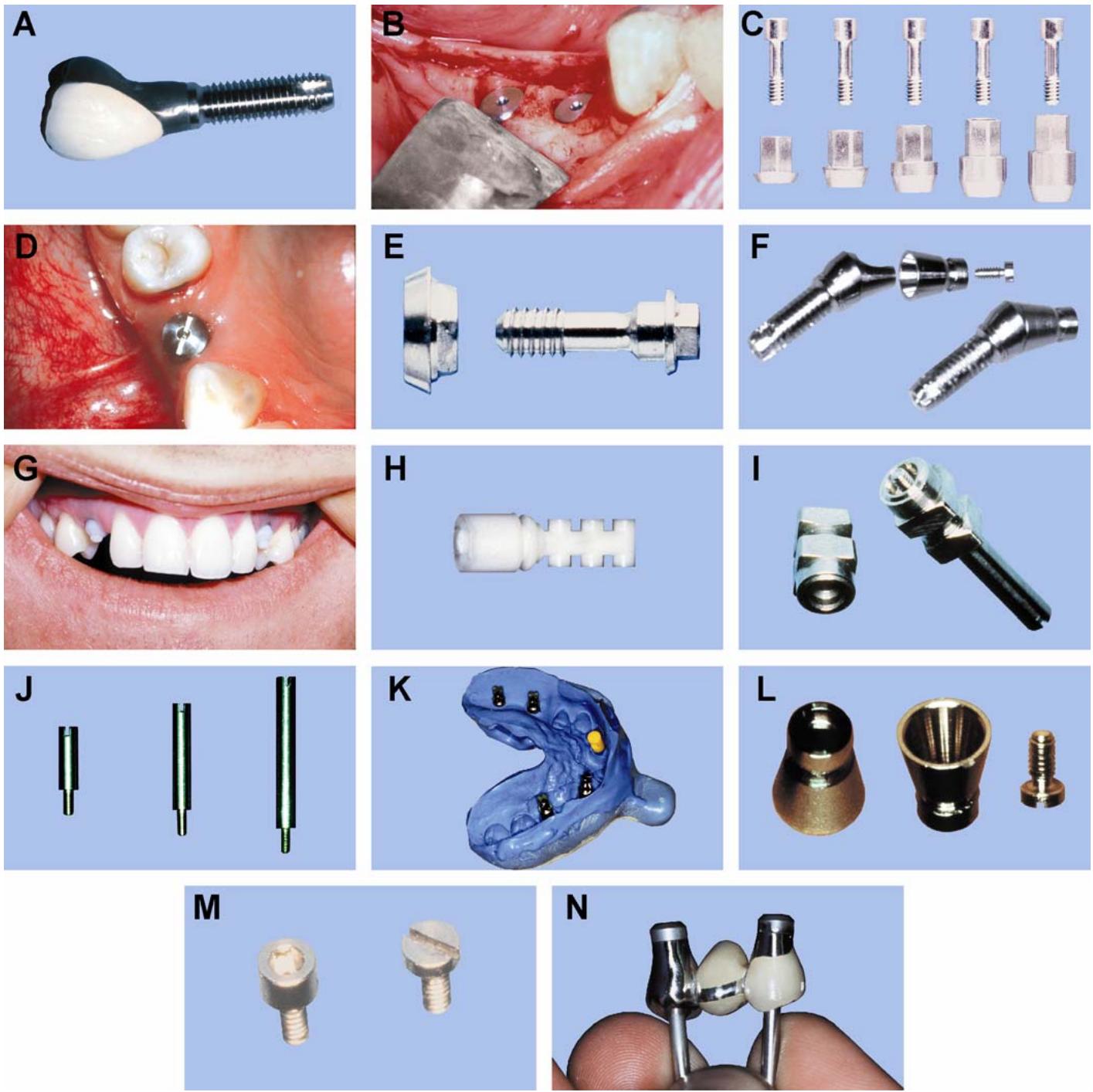
Most implant systems on the market today are similar in the types of components used (Figure 6.2). The following is a description of the standard components necessary to complete a restoration:
6.2.1. Fixture (Figure 6.2-A)
The fixture is a permanent device that is implanted into the bone after the dentist has drilled a hole in the proper location and angle. Fixtures can be of screw type, self-tapping screw, hollow cylinder, hollow screw or many other designs. The most common material for fixtures is Titanium. Titanium is an inert material that develops the titanium oxide layer necessary for the bone-to-implant fusion, which firmly holds the fixture in place. The fixture is normally placed entirely inside the bone with an opening that is flush with the surface of the bone.
6.2.2. Cover Screw (Figure 6.2-B)
The cover screw is placed or screwed into the opening of the fixture at the time the fixture is surgically placed into the bone. Cover screws allow the fixture to osseointegrate with the bone without bone or tissue growing into the opening of the fixture during the healing process.
Figure 6.2. Components of the Implant System.
6.2.3. Abutment (Figure 6.2-C)
The abutment is the portion of the implant that attaches to the fixture and supports and retains the restorative components. The abutment is situated from the surface of the fixture, at bone level, and through the tissue. It stops normally just at or slightly above the gingival tissue. The abutment is held in place with an abutment screw. There are a variety of sizes and styles of abutments available to adapt to different needs.
6.2.3.1. Healing Abutment (Figure 6.2-D)
Healing abutments are used in place of standard abutments following second stage surgery (see paragraph 6.5.2). Healing abutments are desired when a specialized abutment is needed for the restoration or when the length of the standard abutment is not known. These abutments are provided as a one-piece abutment and screw. The abutment allows the tissue to heal and reorganize into a unique peri-implant membrane.
6.2.3.2. Specialized Abutments (Figure 6.2-E)
Each implant system may include specialized abutments, which are used to optimize esthetics, or compensate for the lack of interocclusal space.
6.2.3.3. Angulated Abutment (Figure 6.2-F)
6.2.3.3.1. Angulated abutments are used to compensate for fixtures that are not ideally placed. Fixtures need a sufficient amount of bone to be properly implanted.
6.2.3.3.2. There are cases where the fixtures are angled to the facial or lingual due to improper or necessary implant placement. Angulated abutments can correct this angulation problem up to 30 degrees. However, a correction of this magnitude would create a destructive lever system on the final restoration. This is most commonly seen when a severe labial undercut in the anterior alveolar ridge dictates labial angulation of the fixture. Restoring the dentition with a standard abutment in this position would result in an access channel for the gold screw to emerge through the facial surface of the restoration. Angulated abutments compensate for this by angling the implant a position where the restoration will be placed esthetically.
6.2.3.4. Healing Caps (Figure 6.2-G)
Healing caps are placed on top of the standard abutment during the healing process after second stage surgery. The healing cap protects the abutment screw and the precision milled surfaces of the standard abutment until the restoration or provisional restoration is ready to be inserted.
6.2.4. Temporary Components (Figure 6.2-H)
Temporary components are usually a cylinder, tube, or cap on which a provisional restoration is fabricated. The temporary component attaches to the abutment with a screw, temporary cement, or friction gripping of precisely manufactured components available with some implant systems. The temporary is commonly used in place of the healing cap.
6.2.5. Impression Coping (Figure 6.2-I)
The impression coping is placed or screwed on top of the abutment before the final impression is made. The impression coping is then picked up inside the impression material to transfer the exact location of the fixture or abutment to the master cast. Before the impression is poured with dental stone, an abutment replica (analog) is attached to the impression coping. The cast is then poured, resulting in the analog being positioned in the same location on the cast as the fixture or abutment is in the patient’s mouth.
6.2.6. Guide Pins (Figure 6.2-J)
Guide pins screw directly into the standard, specialized, or angulated abutments; gold cylinders; abutment replicas; or temporary components. They are used during laboratory procedures to ensure the restorative components remain in precise contact with the abutment replica. Guide pins should be used during surgery, final impression, framework waxup, and porcelain application to ensure proper esthetic and functional fabrication of restorations.
6.2.7. Abutment Replicas (Figure 6.2-K)
The abutment replica (laboratory analog) is an exact reproduction of the abutment that attaches to the fixture. It is used as the master die for the technician. The abutment replica attaches to the impression coping prior to pouring the final impression. After the final impression is separated from the master cast, the abutment replica is three dimensionally positioned on the master cast exactly as the abutment is positioned in the patient’s mouth.
6.2.8. Gold Cylinder (Figure 6.2-L)
The gold cylinder is the restorative component that attaches
to the abutment and around which the restoration is built. It is normally 3 to 4 mm in height. The technician attaches the gold cylinder to the abutment replica with a guide pin and then waxes the restoration around cylinder, leaving a hole in the top for access to the screw that holds the cylinder in place. The wax-up is then cast to the gold cylinder, using the lost wax technique.
6.2.9. Gold Screws (Figure 6.2-M)
Gold screws are used clinically to attach the temporary or permanent restoration to the abutment. Two types are used. One is a flat head screw with a slot, and the other is a flat head screw with an internal hexagon or square. The internal hexagon screw has a taller screw head and requires greater interocclusal space.
6.2.10. Protection Caps (Figure 6.2-N)
The protection cap is a stainless steel cap that attaches to the gold cylinder. It should be in place any time sandblasting, grinding, or polishing is accomplished. Its purpose is to protect the surface and shape of the prosthetic component that attaches to the abutment.
¶ 6.3. Procedural Overview
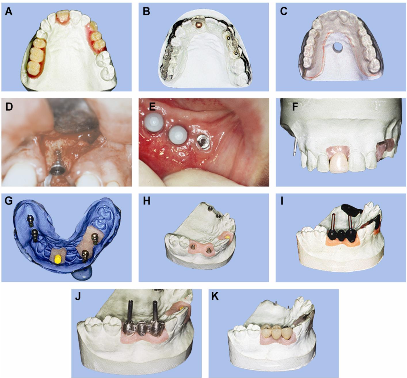
The steps for fabricating an osseointegrated implant are shown below (and in Figure 6.3):
6.3.1. The diagnostic cast is articulated and a preliminary wax-up is accomplished to determine functional and esthetic requirements (Figure 6.3-A)
6.3.2. The dentist accomplishes treatment planning to decide on number and location of implant fixtures. A radiographic stent may be used to help determine if enough bone is available for the implant fixtures (Figure 6.3-B).
6.3.3. A surgical template is fabricated to assist the surgeon in placing the implants in the proper location (Figure 6.3-C)
6.3.4. The first surgical procedure performed is placing the implant fixtures into the bone with the cover screw (Figure 6.3-D)
6.3.5. The second surgical procedure performed is placing the abutment and healing cap (Figure 6.3-E)
6.3.6. Provisional restoration is made if necessary (Figure 6.3-F)
6.3.7. The custom tray is made for the final impression (Figure 6.3-G)
6.3.8. A master cast is made from the final impression and articulated (Figure 6.3-H)
6.3.9. The prosthesis framework is constructed (Figure 6.3-I and -J)
6.3.10. The porcelain, resin, or denture is processed to the framework (Figure 6.3-K)
6.3.11. The prosthesis is inserted.
¶ 6.4. Osseointegration Process
6.4.1. Implants are placed into the mandible or maxillae and held in place through osseointegration. Osseointegration is defined as the direct bone anchorage of an inert material (usually Titanium) that provides a foundation to support the prosthesis. After the implant fixture has been placed into the bone, osseointegration requires new bone formation to firmly hold it in place.
6.4.2. When the implant is first inserted, a layer of oxide forms on the Titanium implant. A layer of glycoprotein approximately 100 microns thick then forms and provides hard direct contact between the bone and the implant fixture’s oxide. Over time, spongy (cancellous) bone develops around the fixture, which will eventually form into compact bone as occlusal forces are applied.
Figure 6.3. Fabricating a Fixed Implant.
6.4.3. Bone-to-implant interface occurs at approximately 3 to 6 months after surgical placement of the implant fixture. The mandible is composed mostly of harder compact cortical bone and, consequently, heals faster than the softer cancellous bone found in the maxillae.
6.4.4. To complete the process, bone-to-implant infusion must occur. An advantage of osseointegration is the ability to transmit occlusal forces directly to the bone. However, careful planning must be done to ensure these forces are distributed more vertically than laterally to reduce traumatic failure of the implant.
¶ 6.5. Implant Surgery
Surgery to place the implants is usually accomplished in the following two stages:
6.5.1. First Stage Surgery. First stage surgery is the process of placing the implant fixtures into the bone, as follows:
6.5.1.1. First, a tissue flap reflection is done to expose the bone. Next, a series of drilling and countersinking procedures are done to produce the proper size hole to receive the fixture. Drilling is accomplished at slow speeds with irrigation to dissipate any frictional heat that may be generated, which would damage the bone thereby compromising osseointegration. Depending on the type of fixture, the hole may need to be tapped to produce threads on the wall of the bone.
6.5.1.2. The fixture is then screwed or tapped into place with the top of the fixture located at the surface of the bone. A cover screw is screwed into the top of the fixture to prevent tissue or bone growth from contaminating the top surface of the fixture. The tissue is then readapted and sutured in place. The fixture remains covered while healing and bone-to-implant fusion takes place. This process will take from 4 to 6 months depending on the type of bone.
6.5.1.3. A temporary prosthesis is used after several weeks have past, but care must be taken not to apply pressure on the fixture during healing. This could cause implant failure, due to exposure and bacterial infiltration.
6.5.2. Second Stage Surgery. Stage two surgeries are more of a minor soft tissue surgery to expose the fixture and attach the abutments:
6.5.2.1. The fixture is first located through the tissue with the help of the surgical stent and an explorer. After the cover screw is located, a small incision is made to expose the cover screw. A punch is then used to remove tissue and expose the entire cover screw. After removing the cover screw, all soft and hard tissue is cleaned away from the fixture opening.
6.5.2.2. Next, the appropriate type of abutment is attached to the fixture, using the abutment screw. If a specialized, esthetic, or angled abutment is used for the restoration, a healing abutment is placed at this stage. When the correct length of standard abutment is used, the abutment should be at or 1 mm higher than the gingival margin in the maxilla and 1 to 2 mm in the mandible. Make sure the abutment is not to long for both esthetics and speech function.
6.5.2.3. After the standard abutments are secured in place, healing caps are placed over the abutment to protect the precision surfaces during the healing process. If a temporary prosthesis is to be used, a healing cap will not be necessary.
¶ 6.6. Radiographic Templates
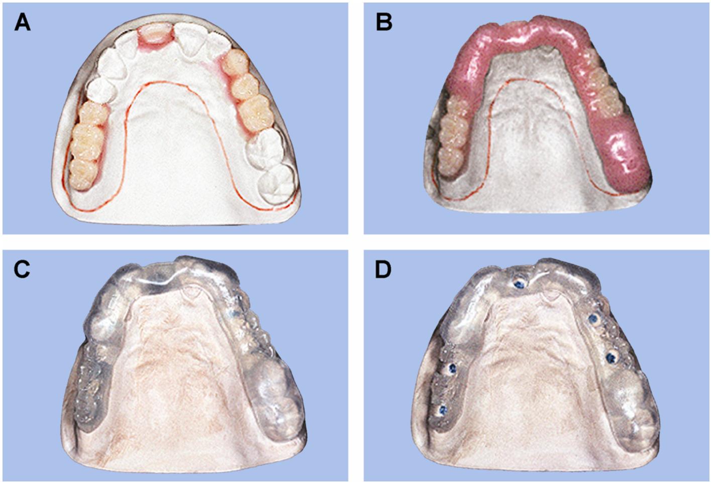
6.6.1. Radiographic templates are used during the radiographic examination to assist in the diagnosis of implant placement in the patient (Figure 6.4). Radiographic templates are clear acrylic with ball bearings, or metal rods, positioned in the template as radiographic reference points above the implant fixtures proposed positioned.
6.6.2. The template can help show the amount of bone available for the implant fixture by comparing the known size of the metal component in the templates to the amount of bone shown on the radiograph regardless of distortion.
6.6.3. Metal rods are also positioned through the center of the proposed restoration, paralleling the axial inclination of the restoration, so it can be used as a guide to the ideal buccal or lingual angle of the implant fixture. In addition, the mesial-distal distance between teeth for single implant fixtures can be evaluated. Any anatomic anomalies may also be discovered, utilizing the guide template.
6.6.4. To fabricate a partial edentulous radiographic template.
6.6.4.1. Articulate the diagnostic cast in MI or use the occlusal registration provided by the dentist.
6.6.4.2. Perform a diagnostic wax-up. Denture teeth may be used or a full contour wax-up performed (Figure 6.4-A). After the wax-up is completed and evaluated, it is a good idea to fabricate a tooth position index with silicone putty for later use.
6.6.4.3. Duplicate the diagnostic cast and wax-up using any standard duplicating process (Figure 6.4-B)
Figure 6.4. Fabricating a Partially Edentulous Radiographic Template.
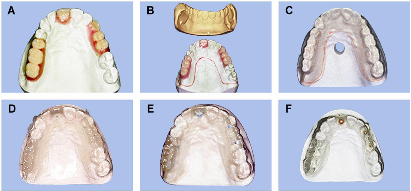
6.6.4.4. Fabricate a vacuum-formed template of the duplicate cast using clear template material (Figure 6.4-C)
Trim the template to just below the gingival margins of the existing teeth and include all of the diagnostic waxed-up areas. After the template is trimmed, lightly air-abrade the areas that are edentulous on the diagnostic cast.
6.6.4.5. Remove the diagnostic wax-up from the diagnostic cast. Survey and block out any undercuts in the edentulous areas of the cast.
6.6.4.6. Apply a separator to the diagnostic cast. Mix self-curing clear acrylic and fill the edentulous areas of the template (Figure 6.4-D). Place the template onto the diagnostic cast and ensure it is seated properly. After the acrylic has cured, trim any excess acrylic, smooth, and polish.
6.6.4.7. The dentist will clearly mark the position of the implants on the diagnostic cast.
6.6.4.8. Place the template on the diagnostic cast. The marks for the position of the implants should be visible through the clear acrylic. Carefully drill a hole at the site of each proposed implant (Figure 6.4-E). The hole must be at the exact location and correct axial inclination of the proposed implants.
6.6.4.9. Place a metal radiographic indicator into each hole and seal in place with acrylic or cyanoacrylate (Figure 6.4-F)
6.6.5. To fabricate a fully edentulous radiographic template.
6.6.5.1. Duplicate the existing denture with clear acrylic, using the technique from Volume 1, Chapter 7, Section 7AK.
6.6.5.2. The dentist will precisely mark the position of the implants on the cast.
6.6.5.3. Place the duplicated denture on the cast and drill holes through the clear denture at the position of each proposed implant. The holes must be at the exact location and correct axial inclination of the proposed implants
6.6.5.4. Place a metal radiographic indicator into each hole and seal in place with acrylic or cyanoacrylate.
6.6.5.5. Trim and polish the template as needed.
¶ 6.7. Surgical Guide Templates
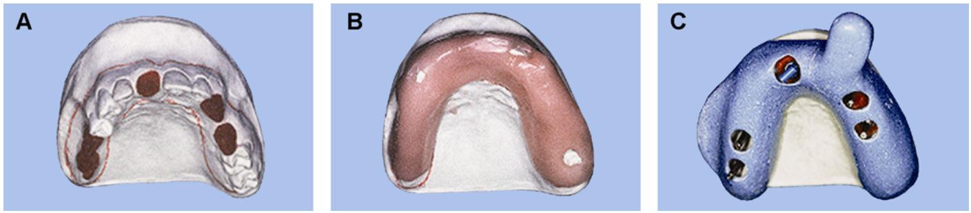
6.7.1. Surgical guide templates are used during the first stage surgery as a guide to implant fixture placement (Figure 6.5)
The surgical guide template provides the surgeon with a prosthetic guide to placement and angulation of fixtures.
Figure 6.5. Fabricating a Partially Edentulous Surgical Guide Template.
6.7.2. Surgical guide templates are essentially the same as radiographic templates. The main difference between the two is that no metal indicators are placed in the surgical guide template. However, the proposed implant area is hollowed out to provide room for the surgeon to drill into the bone with the surgical guide template in place.
6.7.3. The diagnostic wax-up of the proposed restorations is reproduced in acrylic to act as the guide for the buccal-lingual placement of the implants.
6.7.4. To fabricate a partially edentulous surgical guide templates.
6.7.4.1. Articulate the diagnostic cast in MI or use the occlusal registration provided by the dentist.
6.7.4.2. Perform a diagnostic wax-up (Figure 6.5-A)
Denture teeth may be used or a full contour wax-up performed. The silicone putty matrix that was made when fabricating the radiographic template may be used to accomplish the wax-up.
6.7.4.3. Finish the wax-up for the surgical guide template by extending wax over the occlusals of the teeth adjacent to the diagnostic wax-up (Figure 6.5-B). This will be used as a positive seat for the guide template.
6.7.4.4. Process the wax-up in clear acrylic, using the same procedures as processing denture bases (Figure 6.5-C)
Trim and polish the completed surgical guide template.
6.7.4.5. Clean the diagnostic cast of all wax and have the dentist mark the ideal locations for the implant fixtures on the cast.
6.7.4.6. Seat the surgical guide template on the cast and cut out guides in the areas of the proposed implants. The guide slot should not interfere with the facial contour of the restorations. The guide slot must also be wide enough to accommodate the various drills for the size of the implant being used (Figure 6.5-D).
6.7.5. To fabricate for an edentulous surgical guide template.
6.7.5.1. Evaluate the existing denture to see if it meets the functional and esthetic demands of the patient. Make any necessary adjustments:
6.7.5.2. Duplicate the denture in clear acrylic, using conventional methods.
6.7.5.3. The dentist will now mark the implant sites on the cast. (The sites should not interfere with the placement of teeth nor should the angulation affect the facial-lingual inclination of the teeth.)
6.7.5.4. Cut guide holes or a slot at the sites of the proposed implant fixtures. This will give the surgeon a starting point to drill the holes for the fixtures without affecting the positioning of the teeth for the restoration.
¶ 6.8. Custom Tray
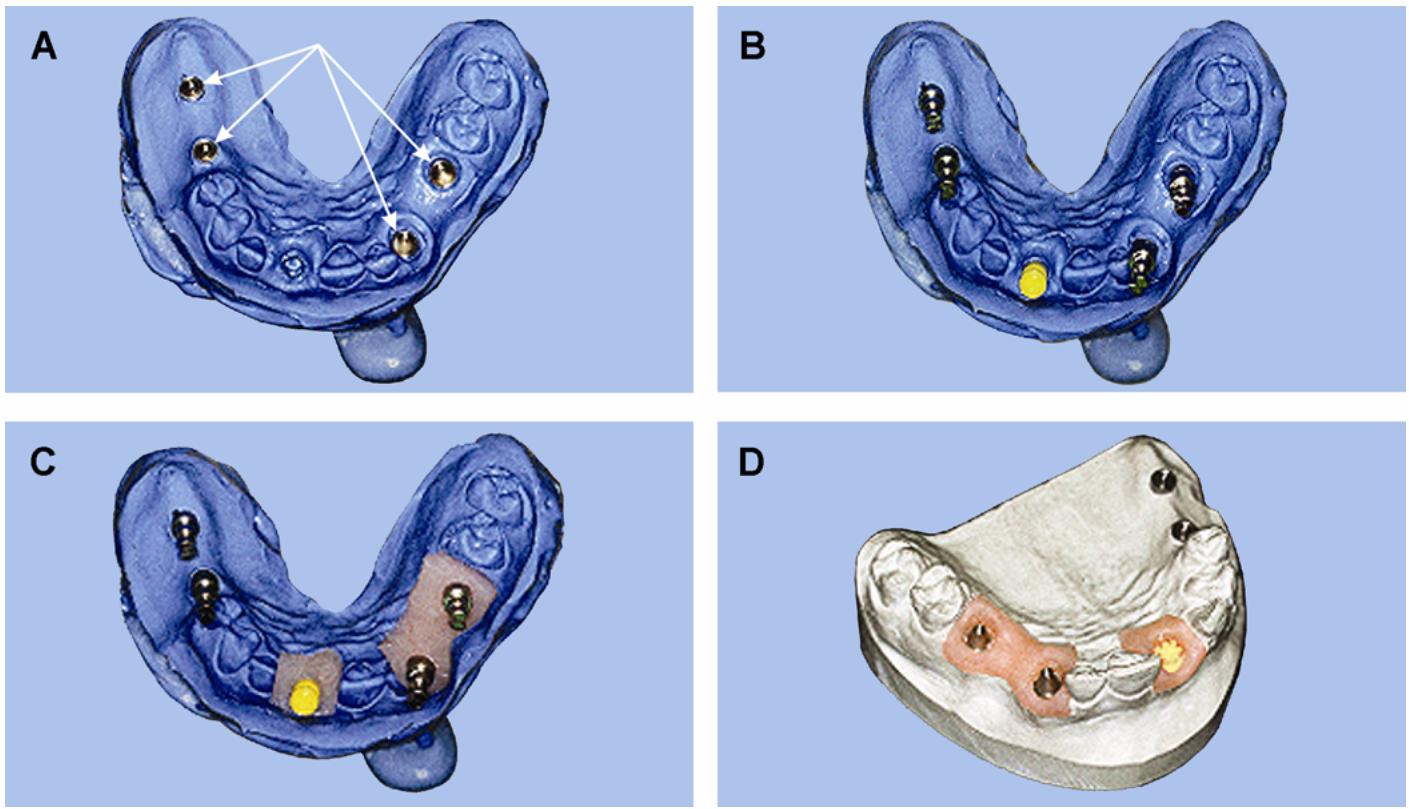
Requirements for fabricating an implant custom tray (Figure 6.6) are essentially the same as those for a standard denture or fixed custom tray:
Figure 6.6. Fabricating an Implant Custom Tray.
6.8.1. The tray must provide for patient comfort while maintaining a uniform thickness of impression material. It must also provide a stable access area for impression copings that utilize guide pins. This is accomplished by an opening in the area above the implants.
6.8.2. Depending on the impression copings used, not all require an opening in the tray. Some impression copings stay on the abutment when removing the impression from the mouth and then are removed and placed into the impression.
6.8.3. The following procedures describe an open impression tray with square impression copings and guide pins. (NOTE: Impression copings that are removed in the impression are recommended for increased accuracy.)
6.8.3.1. To open the custom tray for implant restorations, the dentist first makes an alginate impression for the diagnostic cast. This is done with the healing caps in place on the abutments. The impression is poured and trimmed, using the standard guidelines for diagnostic cast.
6.8.3.2. Follow the dentist’s guidelines for designing the tray and block out any significant tissue undercuts.
6.8.3.3. Block out the area around the healing abutments with wax or clay (Figure 6.6-A)
Using the dentist’s guidelines, apply the necessary amount of relief to the tissue areas to be impressed (Figure 6.6-B).
6.8.3.4. Mix and apply custom tray material to the cast in the usual manner. The only difference is to leave the area open over the blockout that was applied to the healing abutments. After the material has cured, trim the tray to the design line and remove all blockout material (Figure 6.6-C).
¶ 6.9. Master Cast
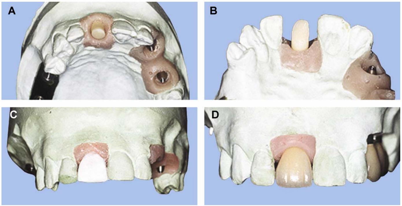
Accuracy of the master cast (Figure 6.7) is of the utmost importance. Precisely accomplish the following steps to ensure the fit of the finished restoration:
6.9.1. Disinfect the impression and then examine the impression copings for stability in the impression material. Also, look for overflow impression material on the seating surfaces of the copings (Figure 6.7-A). Any excess material indicates the copings were not properly seated on the abutments during the impression procedure and, therefore, the impression will need to be reaccomplished.
6.9.2. To attach abutment replica for square impression copings with guide pins, remove the guide pins and gently blow air through the holes to remove debris. Seat an abutment replica on each of the impression copings and attach with a guide pin (Figure 6.7-B)
6.9.3. To attach abutment replica for tapered impression copings, examine the tapered copings’ surface imprint in the impression for any debris or impression defects. Attach an abutment replica to each of the impression copings and then carefully seat the copings into the impression. Firmly seat each coping back into the impression before moving onto pouring the impression.
6.9.4. Use a soft tissue model in the area of the abutments. After the abutment replicas are in place, pour soft tissue material directly into the impression. Because the soft tissue material and impression material are normally both vinyl polysiloxanes, a good separating medium must be first applied to the impression. Apply soft tissue material around each of the abutments, leaving the end of each abutment replica exposed for stone to be poured around it (Figure 6.7-C). When pouring, donot allow the material to run into the adjacent teeth areas.
Figure 6.7. Master Cast Procedures.
6.9.5. Bead and box the impression if necessary. Vacuum mix the die stone and pour the impression. Be careful not to use excess vibration, which may dislodge some types of impression copings.
6.9.6. After the stone has completely set, remove the guide pins and lift the impression from the cast. If tapered impression copings are used, remove the impression with a snap. Examine the cast for any discrepancies. (Ensure the precision surfaces of the abutment replicas are clean and free of any stone.) Trim the cast in the usual manner (Figure 6.7-D).
¶ 6.10. Provisional Restorations
6.10.1. After First Stage Surgery. Temporary, complete or partial dentures can be inserted when the sutures are removed (7 to 10 days after surgery). Existing complete or partial dentures can easily be made to fit over the implant sites. Simply relieve the fixture area of the denture acrylic and reline it with soft-tissue conditioner. Do not apply any pressure to the fixture sites at this time. If acrylic is protruding through the soft liner, perform additional reduction and apply more soft tissue conditioner. Reline the denture in the conventional manner after 1 month.
6.10.2. After Second Stage Surgery. At this point, the abutment and healing caps are protruding through the tissue. For complete dentures, relieve enough acrylic to seat the denture without any interference with the healing cap and then reline it again with a soft-tissue conditioner.
6.10.3. Provisional Restoration for a Single-Tooth, Cement-Retained Implant.
6.10.3.1. Laboratory-Fabricated Provisional (Figure 6.8)
First, take an impression and make a cast with a soft tissue section around the abutment replica. Next, place a temporary cap on the abutment replica and adjust the length so there is no interference with the opposing occlusion (Figure 6.8-A and -B). If a light-cured resin is going to be used it can now be applied, cured, and shaped to the desired contours (Figure 6.8-C). You may also wax up a tooth directly to the temporary cap and process it with heat cured acrylic in the necessary shade. After processing, finish, polish, and ready the provisional for cementation with temporary cement.
Figure 6.8. Laboratory-Fabricated Provisional.

6.10.3.2. Clinically Fabricated Provisional. The dentist will seat a temporary cap onto the abutment in the patient’s mouth. The cap is then adjusted to the proper length. A prefabricated crown shell is then selected to fit over the temporary cap. Additional modifications to the cap may be necessary at this time to provide for sufficient thickness of resin around the cap. The prefabricated shell is filled with proper tooth-colored resin. After the resin has cured, the provisional is removed from the mouth, trimmed, and polished. The finished provisional is held in place with temporary cement.
6.10.4. Provisional Restoration for a Screw-Retained Implant.
6.10.4.1. For a screw-retained, all-acrylic provisional, fabricate a cast with abutment replicas properly positioned and then articulate the cast. Position and attach temporary cylinders onto the abutment replicas, using gold screws or guide pins. Adjust the occlusion and eliminate all lateral and protrusive interferences. At this point, roughen the modified temporary cylinder to enhance the bond with the resin. Apply heat-cured or self-cured acrylic resin or composite resinto the temporary cylinders. Check the resin for occlusal, lateral interferences, and esthetics. Be sure to clean the access holes, thus enabling the guide pin or gold screws to be removed and replaced easily. Finish and polish the provisional restoration.
6.10.4.2. For a screw-retained, cast framework provisional.
6.10.4.2.1. Fabricate maxillary and mandibular casts and articulated them with abutment replicas in place. Position temporary cylinders and reduce them in length to allow seating of temporary tubes over the temporary cylinders. Adjust the temporary tubes to eliminate any occlusal or excursive interference.
6.10.4.2.2. Wax up a framework over the tubes. Place copings over the tubes with a connecting bar between the abutments. Wax up a framework with retentive beads.
6.10.4.2.3. Sprue, invest, and cast the completed framework, utilizing the lost wax technique. After casting, make necessary adjustments to the framework and fit it to the temporary cylinders. Place the temporary cylinders on the abutment replicas with long guide pins.
6.10.4.2.4. Next, cement the framework in place over the temporary cylinders. The framework is now ready for light-cured, self-cured, or heat-cured acrylic resin to be applied, finished, and polished.
¶ 6.11. Procedures for Single-Tooth, Cemented Restoration
6.11.1. For a single-tooth implant, a hex-shaped abutment is used to prevent rotation of the restoration. The dentist will use an abutment positioned 2 to 3 mm below the tissue to prevent a metal band from showing when the restoration is inserted.
6.11.2. There are three methods to fabricate a cement-retained, single-tooth implant—a ceramic cap restoration (paragraph 6.12), a gold cylinder restoration (paragraph 6.13), and a burnout cap restoration (paragraph 6.14)
6.11.3. All of these methods involve first fabricating a master cast with an abutment replica in place. When making the master cast, soft tissue silicone material is applied around the abutment replica. Care must be taken to not run silicone material into the adjacent teeth areas. The soft tissue material will allow for accurate gingival shaping of the restoration. After the casts are fabricated, articulate the master and opposing casts on a semiadjustable articulator.
¶ 6.12. Ceramic Cap Restoration
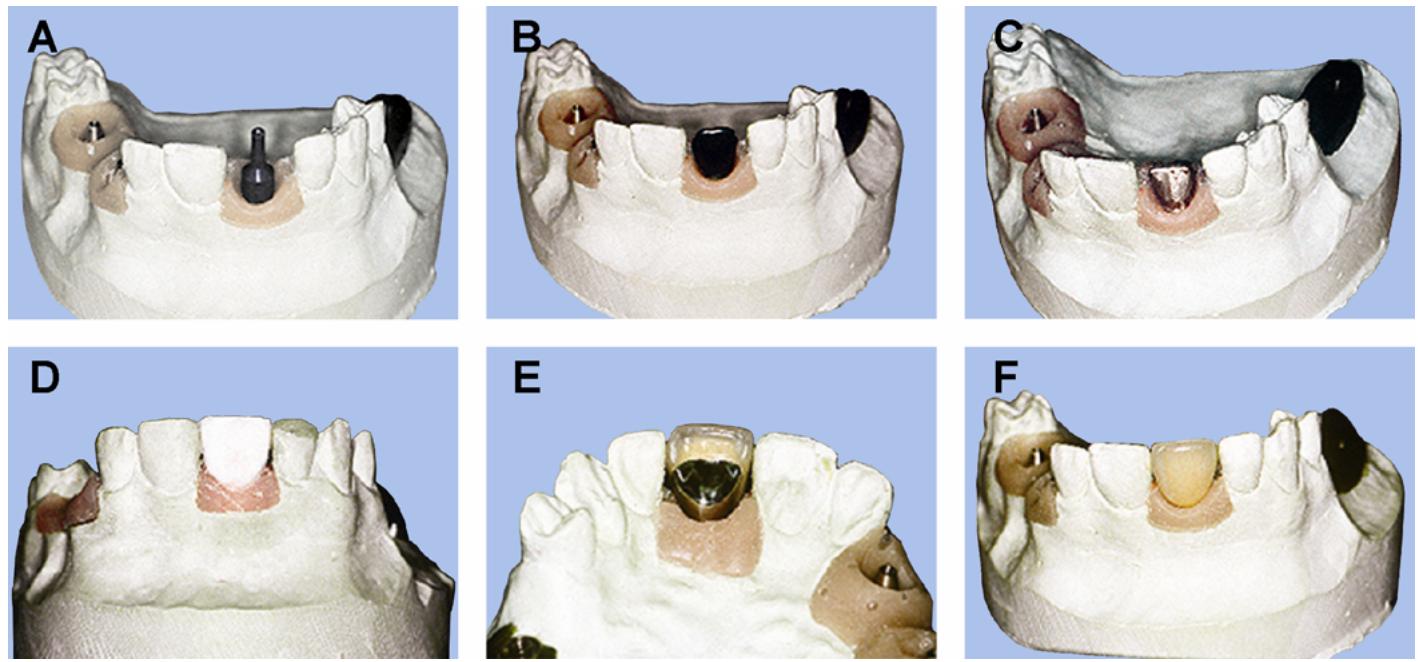
Ceramic caps (Figure 6.9) are made of densely sintered aluminous porcelain and offer the esthetic advantages of the all-ceramic crown. Ceramic caps are available in different lengths, and they are selected based on the interarch space available for the restoration.
Figure 6.9. Cement-Retained, Ceramic-Cap Implant.
6.12.1. Ceramic-Cap Preparations.
6.12.1.1. Seat the appropriate ceramic cap (for example, CeraOne®) onto the abutment replica, check for necessary occlusal space, and evaluate the axial inclination (Figure 6.9-A and -B). It may be necessary to reduce areas on the ceramic cap to provide room for a layer of porcelain to be applied to achieve the contours of the completed restoration. If reduction of the cap is required, use diamond burs on a high-speed, water-cooled handpiece to avoid fracturing the porcelain.
6.12.1.2. The minimum thickness of the ceramic cap must be at least 0.5 mm after adjustments are made. Rinse the contoured ceramic cap under running water and then clean it with hot
steam or place it in an ultrasonic water bath for 10 minutes. Before applying porcelainto the ceramic cap, remove any embedded water by placing it in a warm furnace for 5 minutes.
6.12.2. Porcelain Application.
6.12.2.1. Porcelain that is compatible with an aluminous core must be used to layer the ceramic cap. Conventional metal-ceramic porcelains cannot be used with ceramic caps due to the incompatibility with the aluminous porcelain core. Standard procedures for porcelain application described in Chapter 2 are used to complete the porcelain buildup (Figure 6.9-C). For firing times and temperatures, be sure to follow the manufacturer’s directions of the porcelain system used.
6.12.2.2. After the porcelain application, contour and glaze the restoration. It is now ready to be disinfected and sent to the dentist for insertion (Figure 6.9-D).
¶ 6.13. Gold Cylinder Restoration
Gold cylinders are a cast-to pattern used mainly in the posterior area. Wax is applied directly to the gold cylinder to form a substructure, which will be cast using a noble metal-ceramic alloy.
6.13.1. Substructure Wax-Up.
6.13.1.1. Place the gold cylinder onto the abutment replica and secure it with a guide pin. Wax a metal-ceramic substructure to the gold cylinder, using the techniques in Chapter 2. The wax should extend down to the chamfer on the gold cylinder with a minimum thickness of 0.5 mm.
6.13.1.2. The completed wax-up is then invested, cast, and finished, using the lost wax technique. If debubblizer is used, paint it only onto the wax pattern because debubblizer on the gold cylinder may cause metal casting flash. Take care to avoid trapping bubbles inside the gold cylinder when investing. Any bubbles inside the gold cylinder after casting are difficult to identify. Bubbles on the seating surface of the gold cylinder can give false readings or abrade the plastic, when seating against the abutment replica. Also take extreme care to avoid abrading or damaging the abutment-cylinder surface when removing bubbles.
6.13.2. Porcelain Application. Conventional metal-ceramic porcelain systems and techniques are used to build up and complete the restoration. After porcelain is applied, contoured, glazed, and polished, the restoration is ready for insertion.
¶ 6.14. Burnout Cap Restoration
An acrylic resin cap can also be used to fit over the abutment. The procedures for the burnout cap are very similar to the gold cylinder method. The burnout cap is first seated onto the abutment replica (Figure 6.10-A). Next, complete a metal-ceramic substructure wax-up over the burnout cap (Figure 6.10-B). This wax-up is cast, using conventional lost wax techniques, and porcelain is applied as described in the gold cylinder method above (Figure 6.10-C through -F). The disadvantage of the burnout cap is the absence of the machined fit with the abutment, which is present in the gold cylinder method. One advantage of the burnout cap is that it is less expensive than other methods.
¶ 6.15. Procedures for Screw-Retained Restorations
6.15.1. Overview (Figure 6.11)
6.15.1.1. Single tooth restorations must use the hex-shaped abutment to prevent rotation of the prosthesis. Multiple tooth restorations will use two round or conical abutments to prevent rotation. Screw-retained restorations are normally fabricated using one of two methods, a completely cast (castable) substructure or a cast-to substructure.
Figure 6.10. Cement-Retained, Burnout-Cap Implant.
6.15.1.2. The procedures for screw-retained restorations are very similar to the procedures for making cement-retained restorations, except for a channel to allow access to the screw that retains the restoration. With screw-retained restorations, it is essential the implant fixtures be properly angled so the access hole for the screw is in an acceptable position. The screw opening must be on the lingual for anterior teeth or on the occlusal for posterior teeth. If the angle of the implant is not ideal, an angulated or custom abutment is used to correct the angle or to better position the screw access hole. As with the cement-retained restoration, a master cast must first be fabricated with the abutment replicas in place. It is also a good idea to incorporate the soft tissue cast when fabricating the master cast (paragraph 6.9)
6.15.2. Screw-Retained, Cast-To Substructure. Articulate the master and opposing casts on a semiadjustable articulator, using an occlusal bite registration. Evaluate the vertical space to determine which size gold cylinder will best fit. Before placing the gold cylinder, ensure the surface of the abutment replica is clean for accurate seating. Attach a gold cylinder to each abutment replica, using a guide pin (Figure 6.11-A). (Usually, the 10 mm guide pin is sufficient in length.)
6.15.2.1. Substructure Wax-Up.
6.15.2.1.1. When waxing the framework, keep in mind that it is necessary to support all porcelain applied to the framework during firing cycles by cast metal. Therefore, the screw access opening will need to be lined with a layer of metal. Accomplish this by creating a resin chimney around the guide pin. Build the resin around the guide pin up to a point that will be slightly above the occlusal surface (Figure 6.11-B)
6.15.2.1.2. After the resin cures, remove the guide pin and grind in the occlusion until the resin chimney is no longer above the occlusal surface (Figure 6.11-C). Then wax up the substructure, following all guidelines previously given in Chapter 2 for metal-ceramic restorations (Figure 6.11-D and -E)
Figure 6.11. Screw-Retained, Cast-To Restoration.
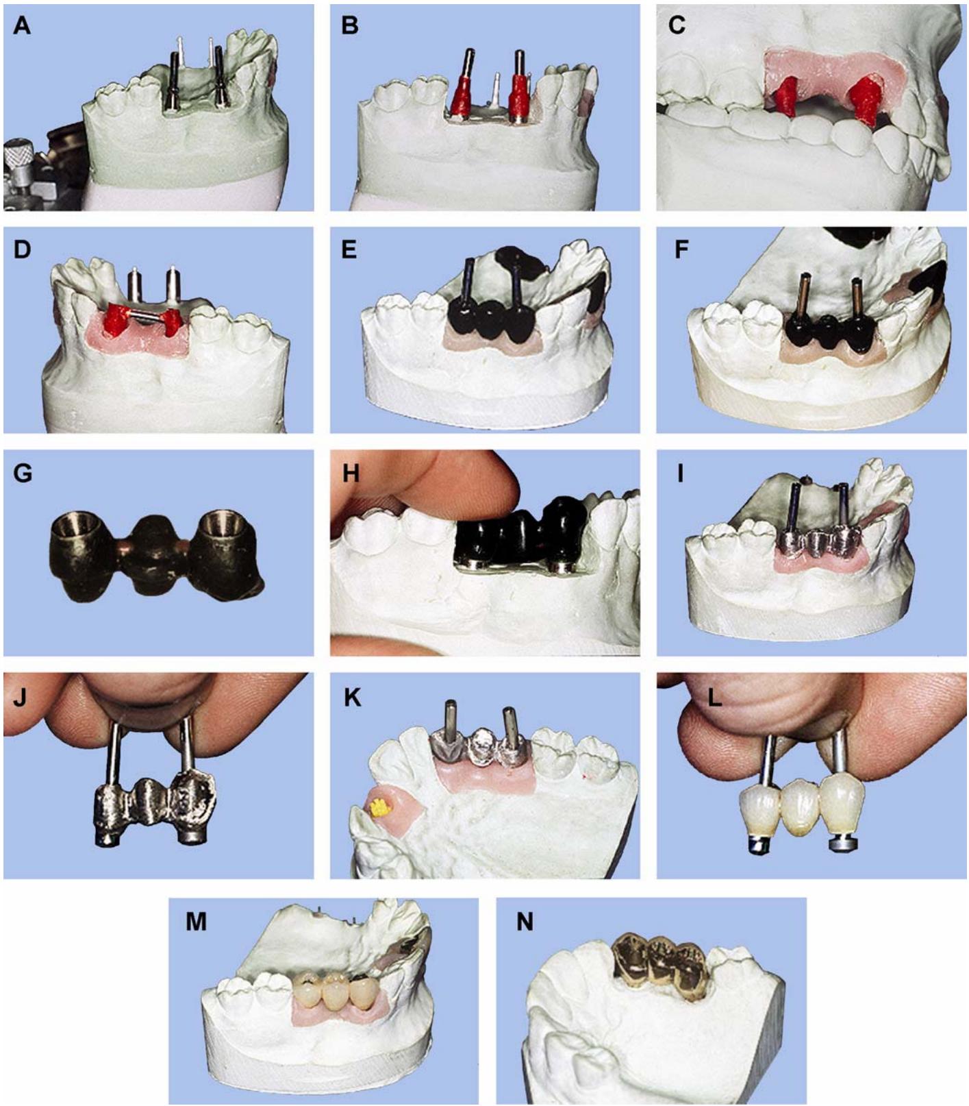
6.15.2.1.3. When cutting back the wax-up, use the soft tissue portion of the cast to ensure the metal collar will be subgingival (Figure 6.11-F)
In addition, all portions of the gold cylinder, except the chamfer, need to be covered in wax. The porcelain will only bond to cast metal, not the gold cylinder. The metal of the gold cylinder does not form an oxide layer, which prevents a porcelain-to-metal bond. Use magnification to ensure all wax is removed from the chamfer portion of the gold cylinder (Figure 6.11-G).
6.15.2.1.4. When fabricating a FPD pattern before investing the substructure, check the fit of the wax-up on the abutment replicas. Use one gold screw to attach one abutment and then look to ensure the opposite end is fully seated (Figure 6.11-H). Repeat this step for the other abutment. If rocking occurs, cut the wax-up, attach both abutments, and then reseal the cut area.
6.15.2.2. Investing and Casting.
6.15.2.2.1. Use conventional spruing techniques to produce implant substructures. If debubblizer is used, paint it only onto the wax pattern. Debubblizer on the gold cylinder may cause metal casting flash. Be sure to follow manufacturer’s directions for mixing investment and burnout procedures.
6.15.2.2.2. Cast by using the normal metal-ceramic casting technique. Keep in mind that the melting range of the alloy used must be lower than the melting range of the gold cylinder. For this reason, a noble alloy is used. Nonprecious alloys should not be used to cast over gold cylinders.
6.15.2.3. Finishing the Substructure.
6.15.2.3.1. Remove all investment from the casting carefully to avoid damage to the gold cylinder. Usually, the investment will fall out of the internal portion of the gold cylinder by tapping on the sprue. If sandblasting is necessary, protect the gold cylinder with wax or protection caps.
6.15.2.3.2. Use magnification to inspect the casting for bubbles, fins, or any defects. Pay particular attention to the gold cylinder seating surface and screw access hole.
6.15.2.3.3. After the gold cylinder and screw access hole is clean, seat the framework onto the cast and check the fit (Figure 6.11-I)
If necessary, an FPD can be cut with a disc through the pontic, reattached to the abutment replicas with guide pins, sealed together with resin, and soldered.
6.15.2.3.4. After a precise fit to the abutment replicas is established, attach a protection cap with a guide pin before proceeding to metal finishing (Figure 6.11-J). Always use protection caps to protect the internal and seating surfaces of the gold cylinder. Now, finish the porcelain bearing surfaces in the same manner as any porcelain fused to metal crown (Figure 6.11-K). At this point, FPD frameworks should be tried in the mouth to check for proper fit.
6.15.2.4. Applying Porcelain (Figure 6.11-L through -N)
First, prepare the framework in the manner prescribed by the porcelain manufacturer. Porcelain application is essentially the same for implants as conventional metal-ceramic crowns. EXCEPTION: Clean all porcelain from inside the screw access holes and gold cylinder seats before firing and use protection caps while grinding porcelain during contouring procedures.
6.15.3. Screw-Retained, Castable Substructure (Figure 6.12)
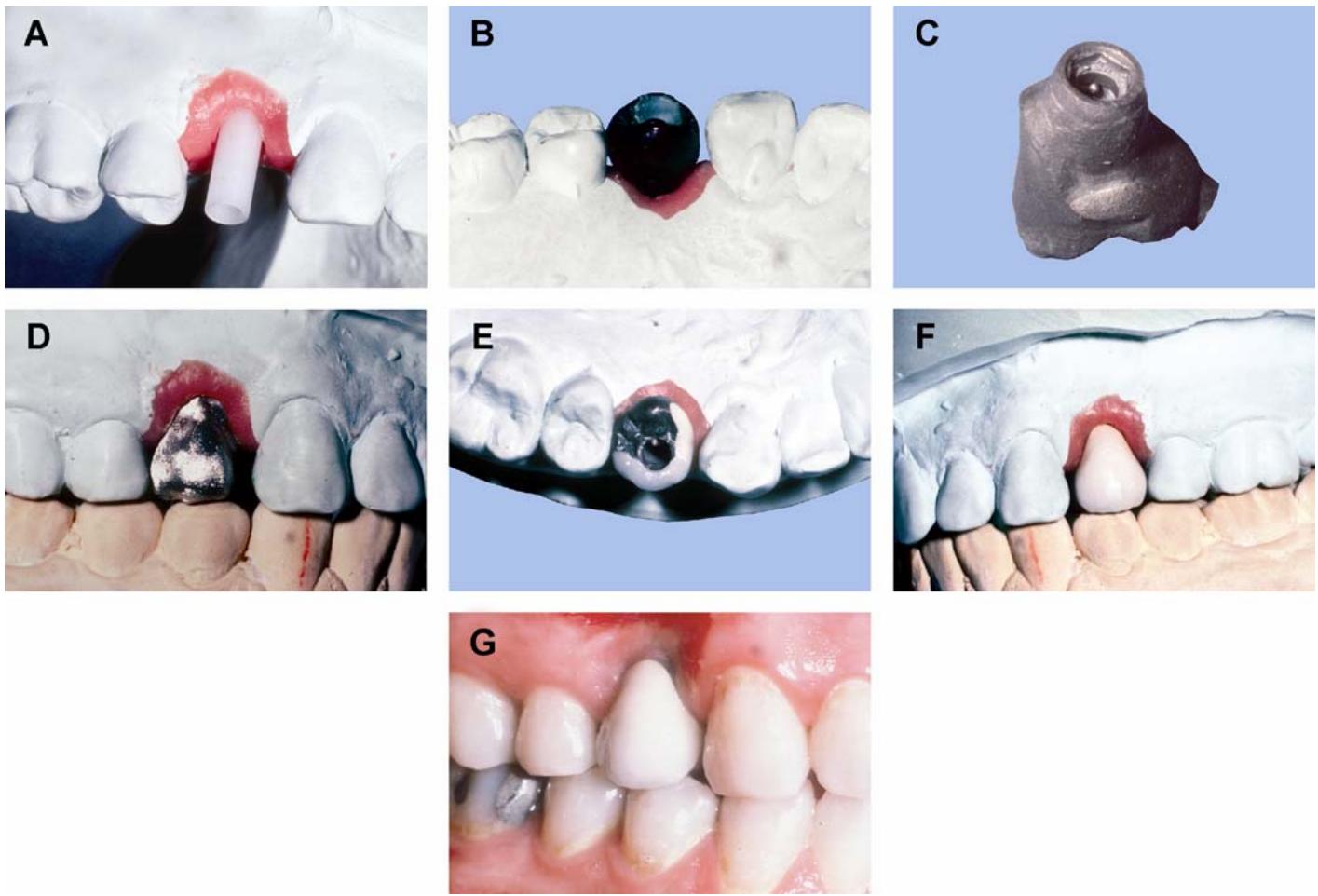
6.15.3.1. A common type of screw-retained, castable substructure is known as the U.C.L.A. abutment. The U.C.L.A. abutment is a plastic pattern that serves as both the abutment and the gold cylinder and is screwed directly to the implant fixture (Figure 6.12-A). The U.C.L.A. abutment has a 0.5 mm collar on the plastic pattern that serves as the metal porcelain junction. Fabrication procedures are essentially the same as the cast-to screw-retained implant.
Figure 6.12. Screw-Retained, Castable Substructure.
6.15.3.2. Start by fabricating the master cast, using a fixture replica versus the abutment replica. Articulate the completed master and opposing casts on a suitable articulator.
6.15.3.3. Next, wax the substructure following guidelines for metal-ceramic substructures (Figure 6.12-B)
Be sure to extend the screw access hole to the height of the occlusal surface to give support to the porcelain when firing.
6.15.3.4. Cast the wax-up, using a porcelain compatible metal (Figure 6.12-C)
Prepare the casting for porcelain, then apply, fire, and contour porcelainto the necessary contours (Figure 6.12-D through -G). Ensure the screw access hole is free from porcelain or any other material.
6.15.3.5. The last step is to finish or mill the surface of the restoration that seats against the implant fixture. When a castable substructure is used, the surface that seats against the implant fixture is not as smooth as a machined abutment supplied by an implant manufacturer.
6.15.3.6. These two surfaces must have intimate contact for successful retention of the restoration. The best way to accomplish this is to use an electric discharge machine (EDM). The EDM uses electric current to spark erode the surface of the casting until it has a smooth intimate contact with an implant fixture replica. Another method is called lapping. It uses grinding compound and small hand drill to lap or grind the surface of the casting against an implant fixture replica until it is smooth and has intimate contact with the fixture replica.
¶ 6.16. Procedures for Implant-Retained Removable Prosthesis
Several different types of implant devices can retain removable prostheses. Common devices are the bar and clip attachment (paragraph 6.17 and Figure 6.13), magnets, and ball attachment. The common number of implants used to retain a denture is two. The fabrication procedures for prostheses that use these attachments are very similar.
¶ 6.17. Bar and Clip Retained Overdenture
One popular type of plastic bar and clip attachment for a removable prosthesis is called the Hader bar. A Hader Bar is cast into metal and uses a plastic retaining clip that can be easily replaced when necessary. The bar and clip normally uses two implants—usually one in each canine area, using a standard abutment and gold cylinder with a bar connecting the gold cylinders. Located inside the resin on the tissue side of the denture is a plastic clip that retains the denture when seated.
6.17.1. Custom Tray and Master Cast. First, make a custom tray (Figure 6.13-A) by following the steps outlined in paragraph 6.8. Using the custom tray, the dentist will take a final impression with impression copings on the abutments (Figure 6.13-B). Attach abutment replicas to the impression copings and then pour and trim the final impression (Figure 6.13-C). (Additional guidance on the master cast is available in paragraph 6.9.)
6.17.2. Baseplate and Occlusion Rims. Attach gold cylinders to the abutment replicas, using long guide pins. Block out around each abutment to prevent the baseplate resin from attaching to the gold cylinders. Make a standard baseplate with the areas around the gold cylinders open (Figure 6.13-D). When making the occlusion rims, leave the area around the guide pins open to prevent the wax from interfering with access to the guide pins (Figure 6.13-E). Use standard dimensions for the occlusion rims (Volume 1, Chapter 7, Section 7H).
6.17.3. Articulation. Articulate the master cast and opposing, using the face bow and interocclusal registration. It may be necessary to use shorter guide pins to eliminate interferences with the opposing cast.
6.17.4. Trial Denture.
6.17.4.1. Follow standard tooth arrangement procedures for the desired type of setup. If interference is encountered with the guide pins, the tooth must be altered or omitted for the try-in (Figure 6.13-F). If a tooth is altered for the try-in, a replacement tooth will be set during the final wax-up when guide pins are no longer used. The completed setup will then be tried in the patient’s mouth and evaluated for function and esthetic requirements.
6.17.4.2. Make any necessary changes to the setup using the dentist guidance from the try-in (Figure 6.13-G)
In order to maintain the relationship of the setup to the abutments, make a silicone facial matrix of the final setup. Be sure to make grooves in the land areas of the cast before making the matrix to help reorient it to the cast later.
6.17.5. Bar Fabrication.
6.17.5.1. First, attach the gold cylinders to the master cast, using guide pins (Figure 6.13-H)
Cut a piece of plastic bar to fit between the gold cylinders passively. Keep the plastic bar straight to allow for easy seating of the clip.
6.17.5.2. Position the plastic bar a minimum of 2 mm above the tissue to allow for easy cleaning. Attach to the gold cylinder with inlay wax (Figure 6.13-I).
6.17.5.3. Flow the wax over and around the gold cylinder to blend in the bar attachment. Sprue, invest, and cast the completed wax-up (Figure 6.13-J).
6.17.5.4. Finish the casting to the polished stage without altering the shape of the bar. When finishing, use protection caps on the gold cylinders to prevent damage to the seating surfaces (Figure 6.13-K). Attach the finished bar to the abutments with gold screws and check for an accurate fit (Figure 6.13-L).
Figure 6.13. Bar and Clip Overdenture Procedures.
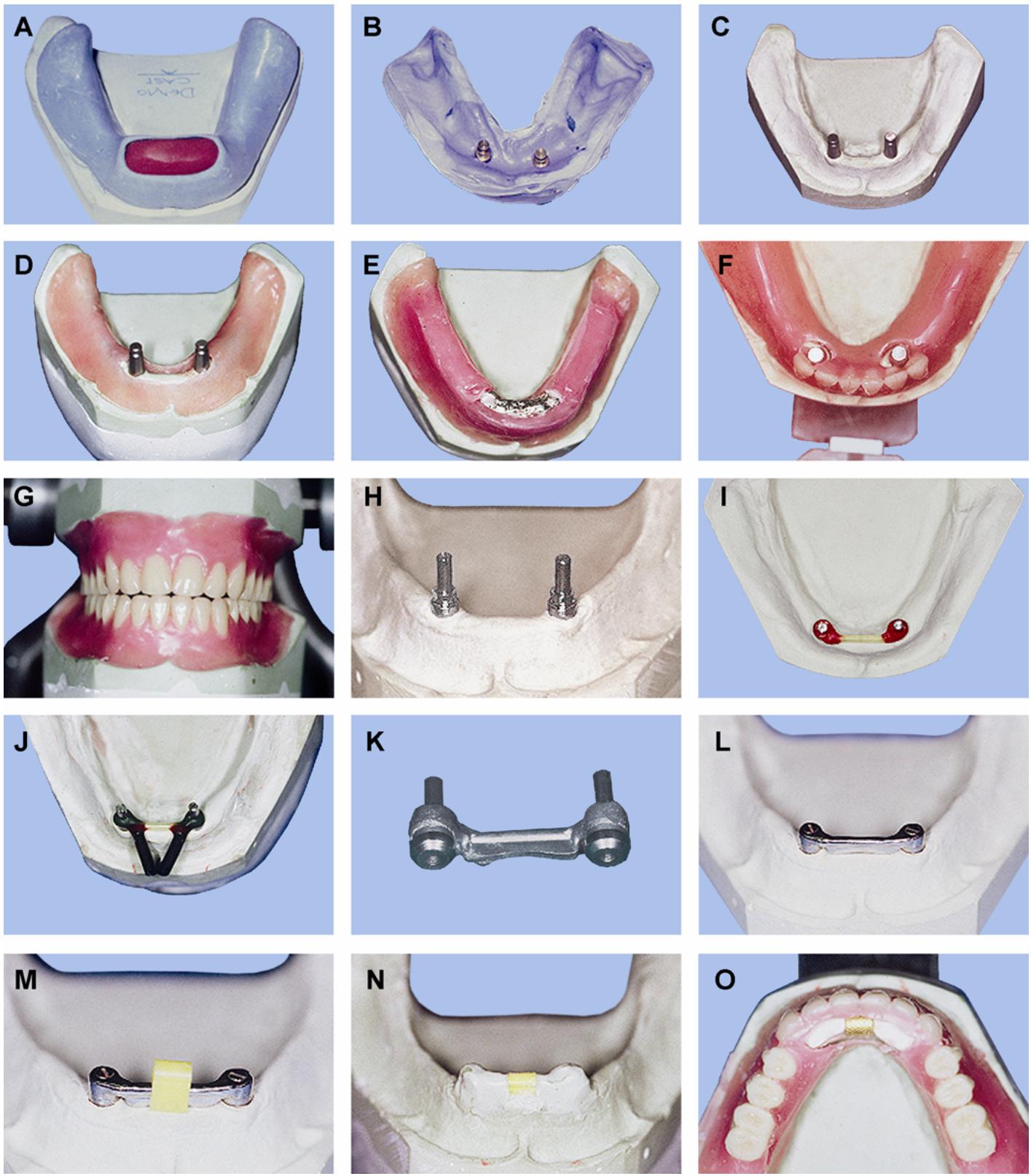
Figure 6.13. Continued.
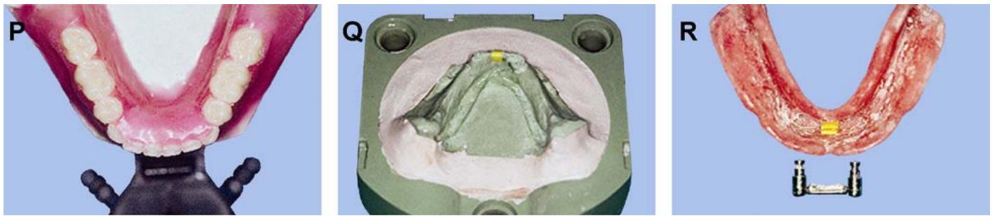
6.17.6. Denture Completion.
6.17.6.1. Position the fabrication plastic clip on the bar and adjust the clip to follow the contours of the tissue when the clip is fully seated onto the bar (Figure 6.13-M)
6.17.6.2. Seat the clip and apply stone to stone separator to the anterior portion of the cast. Mix and flow stone around the bar to blockout the entire bar, leaving the clip exposed and flush with the top of the block out (Figure 6.13-N). This allows the clip to be picked up in the resin when processing the denture base without engaging any resin around the bar.
6.17.6.3. Remove the teeth from the trial denture wax-up and seat them into the silicone matrix made earlier (paragraph 6.17.4.2)
Seat the matrix onto the indexes in the master cast land area and flow the wax, attaching the teeth to the cast (Figure 6.13-O). Fill in all space with wax and contour the denture base to complete the final wax-up (Figure 6.13-P).
6.17.6.4. Verify the occlusion and then proceed to process the denture base, using standard processing techniques (Figure 6.13-Q)
When deflasking, be careful to avoid damaging the bar.
6.17.6.5. Remount the denture to the articulation and equilibrate any processing errors. Finish and polish the denture using conventional techniques. Remove the fabrication clip and install the final retentive clip. This final step is usually completed during insertion of the completed denture (Figure 6.13-R).
DentalTechnology.org is dedicated to preserving, teaching, and advancing the craft of dental technology.
This resource is made possible by Russellville Dental Lab, a full-service dental laboratory in Russellville, Kentucky, serving clinicians across the USA for more than 70 years.