¶ Chapter 7 — SPECIAL PROSTHESES
Reference Edition
This chapter is part of the Air Force Dental Laboratory Manual (2005) – Digitally Restored Edition.
This edition preserves the original publication while correcting OCR errors, restoring formatting, reconstructing damaged tables where necessary, and improving digital readability.
The technical content has not been rewritten, modernized, expanded, or altered.
It is provided as a professional reference. Modern instructional material is published separately throughout DentalTechnology.org.
¶ Section 7A — Treatment Appliances
¶ 7.1. Types of Basic Orthopedic Appliances
7.1.1. Introduction. The basic orthopedic appliance has many different names, including night guard, maxillary orthopedic appliance, occlusal orthopedic appliance, and occlusal splint. A basic orthopedic appliance can be made of hard or soft material for either the maxillary or mandibular arch. The hard appliance may be fabricated, using self-curing orthodontic acrylic, heat-cured acrylic, light-cured acrylic, microwave-cured acrylic, or vacuum-formed plastic. The soft appliance is usually fabricated, using mouthguard material (0.15-inch thick). This section will describe the self-curing, sprinkle-on technique.
7.1.2. Patient Treatment.
7.1.2.1. These appliances can be used to (1) stabilize the teeth, (2) treat temporomandibular disorders and provide pain relief, (3) increase occlusal vertical dimension, and (4) reduce an excessive rate of tooth wear.
7.1.2.2. The basic orthopedic appliance may be fabricated with the mandible in different positions. These positions can range from centric relation to any position forward of centric relation that can be tolerated by the patient. The centric relation position of the mandible (or terminal hinge position) provides for the most repeatable position of the mandible.
7.1.2.3. A basic orthopedic appliance can be a passive appliance that uses a flat surface parallel to the occlusal plane or an active appliance that usually has occlusal indentations approximately 1 mm deep guiding the mandible to a predetermined position on the appliance.
7.1.2.4. Most basic orthopedic appliances are made with simultaneous, even contact of all posterior stamps cusps and incisal edges of the opposing arch in the centric position provided by the dentist. These appliances are usually fabricated with a mutually protected occlusion, which provides for a anterior guide plane that acts as a guiding ramp to disclude all potential posterior eccentric contacts.
7.1.3. Procedures for Construction of a Basic Orthopedic Appliance (Self-Cured Acrylic)
7.1.3.1. Mount Casts.
7.1.3.1.1. Before the appliance can be made, the casts must be mounted on an articulator with the desired mandibular position and a space separating the opposing teeth. For specific procedures on articulating, refer to Volume 1, Chapter 6.
7.1.3.1.2. Although it is not absolutely essential for the maxillary cast to be mounted using a facebow transfer, it will provide a more accurate relationship of eccentric contacts and centric contacts if the vertical opening is to be changed.
7.1.3.1.3. Lateral records may also be used to adjust the horizontal condylar guidance. If the dentist provides these records, you will be able to program the articulator to simulate the mandibular movements of the patient. If these records are not provided, the dentist must be willing to accept some degree of error in these positions and make the necessary adjustments in the mouth. If the dentist does not provide a facebow transfer, he or she must provide an interocclusal record of the same thickness and relationship desired for the finished
appliance. (Be sure to tighten the set screw on the incisal pin to prevent the occlusal vertical dimension from moving accidentally.)
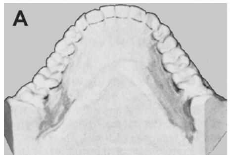
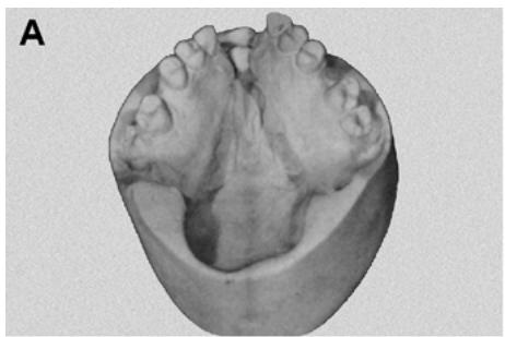
7.1.3.2. Survey and Design. Once the casts have been properly mounted on the articulator with the desired amount of occlusal vertical dimension opening, the next step is to survey the maxillary cast (Figure 7.1-A). Survey the buccal and lingual surfaces of the posterior teeth with a carbon marker. The design of the appliance should extend 0.5 mm beyond the height of contour on the buccal of the posterior teeth and 1 to 1.5 mm below the incisal edge along the labial surfaces of the anterior teeth. The lingual design should be a horseshoe shape that covers the rugae.
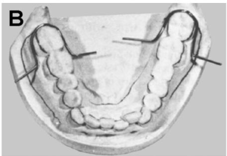
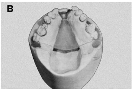
7.1.3.3. Block Out Undercuts. Using baseplate wax, block out undercuts along the lingual gingival crevice, embrasures, margins of restorations, deep occlusal grooves, and prominent rugae. Apply utility wax, following the design along the facial surfaces of the teeth and inside the palate to establish the border of the appliance (Figure 7.1-B). Seal the utility wax to the cast and flatten the top edge of the wax, just exposing the design line. The utility wax will help control the flow of acrylic and establish a definite border to the appliance.
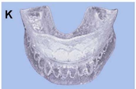
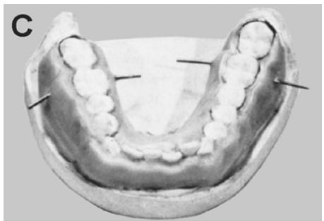
Figure 7.1. Basic Orthopedic Appliance.
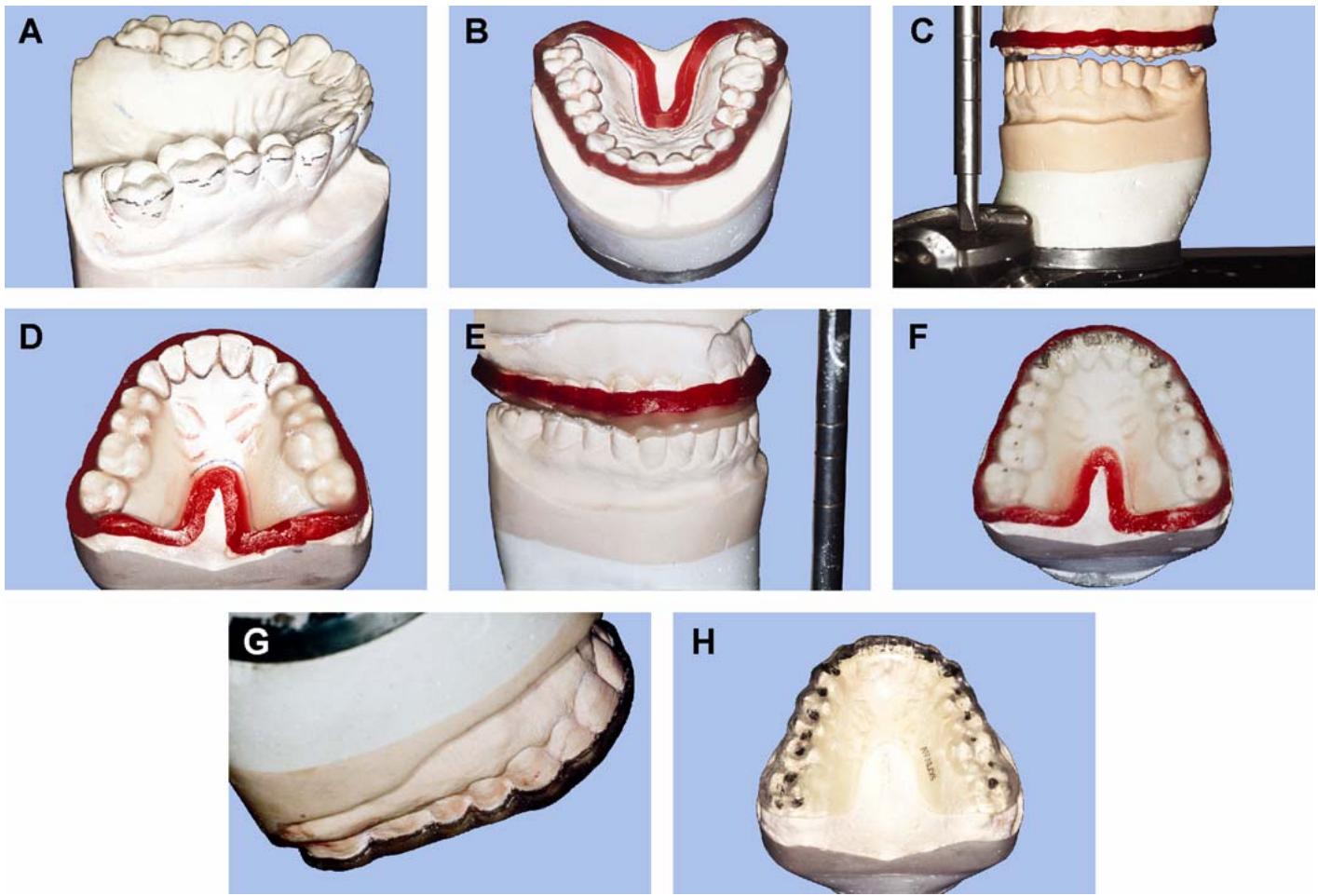
7.1.3.4. Set the Guide Table for Anterior Guidance. Set the incisal guide table to ensure there is adequate space for acrylic in lateral and protrusive excursions.
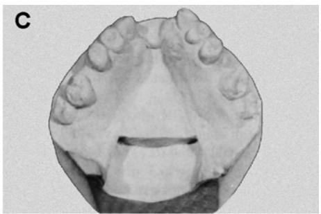
7.1.3.4.1. Loosen the centric locks and place the upper member of the articulator in protrusive. Rotate the incisal guide table until the incisal guide pin separates the anterior teeth 1 to 2 mm at the closest point (Figure 7.1-C). Tighten the set screw on the guide table at this position.
7.1.3.4.2. Place the upper member into a lateral excursion. Adjust the appropriate incisal guide table wing until the guide pin separates the posterior teeth 1 to 2 mm at the closest point. Lock the guide table set screw at this position. Repeat this step for the other lateral excursion.
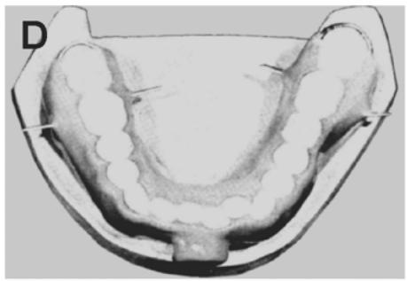
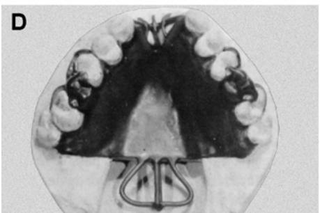
7.1.3.5. Apply Resin. Orthodontic resin provides the best appliance and is easiest to control. Apply a tinfoil substitute to the maxillary arch and opposing occlusal surfaces. To minimize the shrinkage and distortion that always accompanies the polymerization of acrylic resin, apply the resin in sections (Figure 7.1-D), using the sprinkle-on technique. The first three applications of acrylic provide a minimum thickness of resin and must not be allowed to contact the mandibular teeth.
7.1.3.5.1. Sprinkle the polymer on one of the posterior sections to include only the occlusal and lingual surfaces of the teeth and tissue. Moisten the powder with monomer and keep it moist to prevent porosity. Close the articulator and check to see that the mandibular cusps do not contact resin. Allow each section to cure before proceeding to another. To help reduce porosity in the cured appliance, place the cast in a closed container with a monomer-soaked cotton roll while the curing process takes place.
7.1.3.5.2. After the three sections have been joined together, sprinkle the resin for the occlusal portion of the appliance. Moisten the previously formed base with monomer and sprinkle resin onto the entire occlusal surface.
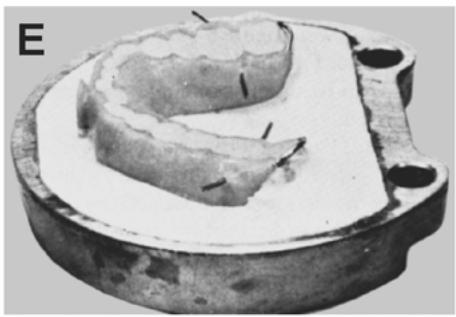
7.1.3.5.3. Build up the resin thick enough so opposing cusp and incisal edges will contact when the articulator is closed. Let the resin become doughy and then close the articulator into centric position. Repeatedly close the articulator and move the upper member through lateral and protrusive excursions while the resin is still in the doughy state (Figure 7.1-E).
7.1.3.5.4. In the anterior region, the goal is to create an inclined plane that discludes all potential posterior eccentric contacts. With the incisal guide table properly set (paragraph 7.1.3.4), this should be easily achieved.
7.1.3.5.5. When all the imprints have been established, close the articulator and place it in a closed container; for example, a small plastic bucket with lid. Allow the resin to polymerize according to the manufacturer’s guidelines.
7.1.3.6. Refining Contacts.
7.1.3.6.1. The occlusal contacts must be refined through identification of the various imprints and adjustment. Good methods for distinguishing between centric and eccentric contacts use red and black articulating film.
7.1.3.6.2. Place a piece of red articulating film on the occlusal surface and gently tap the articulator closed until red marks are readily visible on the acrylic. Next, use the black articulating film on the occlusal surface, following the imprints made, to identify the eccentric contacts. The objective of adjusting the centric contact areas is to reduce the broad base contact to a smaller point contact.
7.1.3.6.3. Only the mandibular buccal cusp tip indentations at the greatest depth are permitted to remain. Care must be taken when reducing the broad base contacts to avoid grinding through the acrylic and damaging the cast. If holes are ground through into the cast, they cannot be accurately repaired because a portion of the cast is now missing.
7.1.3.6.4. In lateral and protrusive movements, the anterior bite plane bears the functional load for the appliance. Therefore, all posterior eccentric contacts must be eliminated and anterior guidance “ground in” to produce a smooth, gliding motion. When fully adjusted, the appliance should hold the shim stock between the appliance and all mandibular buccal cusps in centric occlusion only. When the shim stock is pulled through the anterior region, it should be able to drag across the mandibular anteriors in centric occlusion.
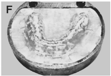
7.1.3.6.5. In the eccentric positions, the posterior cusps should not touch the acrylic resin and the anterior should only cause a posterior separation of 1 to 2 mm. The contacts should appear like those in Figure 7.1-F.
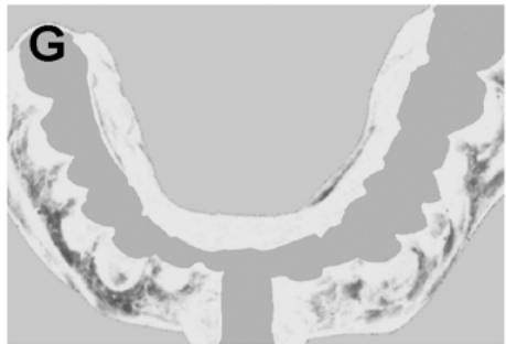
7.1.3.7. Bulk Finishing. Most of the finishing should be done while the appliance is on the cast to minimize distortion or warpage. Remove the utility wax from the borders of the appliance. If necessary, boiling water may be used to eliminate the wax, but care must be taken to avoid warping the appliance. Reduce the overall bulk of the appliance until you obtain a uniform thickness of approximately 1 to 2 mm. Contour the resin along the facial contours in a scalloped fashion approximately 1 mm thick (Figure 7.1-G). Be careful not to eliminate any of the centric stops or disturb the anterior guidance.
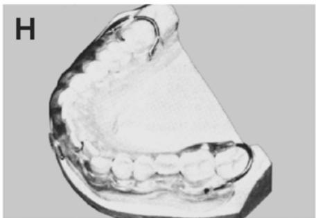
7.1.3.8. Completion. Carefully remove the appliance from the cast by gently lifting from the posterior area first to allow the appliance to disengage the undercuts on the facial of the anterior teeth. The acrylic resin along the facial should extend 0.5 mm beyond the height of contour of the posterior teeth and 1 to 1.5 mm below the incisal edge of the anterior teeth. Lightly pumice and polish the occlusal areas and avoid eliminating any of the contacts incorporated into the appliance. Exercise extreme caution not to overheat the resin and warp the appliance during pumicing and polishing. Clean and disinfect the appliance before delivery (Figure 7.1-H).
¶ 7.2. Soft Acrylic Mandibular Orthopedic Appliance
A basic orthopedic appliance using soft resilient mouthguard material is essentially fabricated in the same manner as the thermoplastic vinyl mouth protector discussed in paragraph 7.4. The only significant differences are that a mandibular cast is often used and dentists often desire the material to extend as far as possible into the posterior lingual flange area.
¶ 7.3. Other Basic Orthopedic Appliance Designs
Depending on treatment needs, dentists will occasionally request different designs for oral orthopedic devices. Such devices may include anterior bite planes, mandibular bilateral p osterior splints, and anterior repositioning devices. Consult the prescribing dentist for specific fabrication details.
¶ 7.4. Fabricating a Thermoplastic Vinyl Mouth Protector
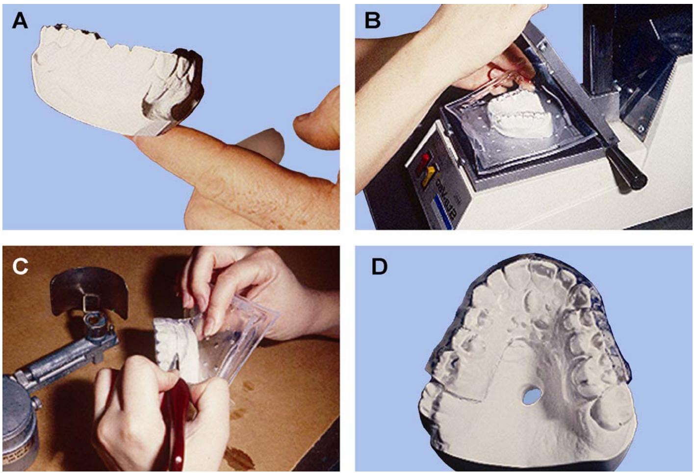
In the fabrication of a vinyl thermoplastic mouth protector, the dentist will furnish an alginate impression of the patient’s maxillary arch. The dental technician will perform the following steps (Figure 7.2):
7.4.1. Pour a master cast in artificial stone.
7.4.2. After separating the cast from the impression, draw the outline of the mouthguard on the cast with a soft lead pencil. Trim the cast as close to the outline as practical. (The thickness of the base should not exceed 6 mm). Do not create undercuts on the cast that would interfere with removal of the mouth protector. The reason for trimming the cast as specified is to facilitate the vacuum formation and minimize stretching and thinning of the vinyl plastic during the molding (Figure 7.2-A). A large, oversized cast would result in a thin mouth protector with poor serviceability. At this time, allow the cast to dry because air will not pass through a cast satu rated with water. Print the patient’s name on the cast.
Figure 7.2. Mouth Protector Fabrication.
7.4.3. Determine the exact molding procedure used. To some extent, this depends on the type of equipment used. The directions furnished by the manufacturer should produce satisfactory results. Most commercial machines consist of a perforated plate connected to a source of vacuum, an electrical heating element, and a metal frame the vinyl plastic blank is clamped into. The molding procedure in general is as follows:
7.4.3.1. Clamp a vinyl plastic sheet in the frame and place it under the heater. Estimate the molding temperature by the amount the sheet of vinyl plastic material “sags” as it softens. Excessive softening of the material will result in undesirable stretching and thinnin g of the mouth protector. Sharp reproductions of the surface detail are not necessary.
7.4.3.2. Dip the dry cast in water for 2 or 3 seconds and place in position on the perforated plate. This wetting provides enough surface moisture to prevent the vinyl plastic from sticking, but it does not affect the passage of air through the cast.
7.4.3.3. Turn the vacuum on and move the frame to the molding position. Hold in this position until the vinyl plastic is completely adapted to the cast (Figure 7.2-B).
7.4.3.4. Turn off the vacuum and release the clamp on the frame. Set the cast with the mouth protector aside until it cools thoroughly.
7.4.3.5. After cooling, trim excess vinyl plastic material away with scissors or a warm knife blade (Figure 7.2-C)
Remove the mouth protector from the cast and polish the periphery with pumice. Clear any cloudy areas caused by polishing by lightly flaming the mouth protector over a Bunsen burner or with an alcohol torch. Clean and disinfect the mouth protector and replace it on the cast until it is delivered to the patient (Figure 7.2-D).
¶ 7.5. Sleep Apnea Appliance
Sleep apnea is a condition in which airflow is restricted, causing breathing interruptions during sleep. In some cases, an appliance can be made to reduce the chances of interruptions and allow air to freely pass into the lungs. The sleep apnea appliance repositions the lower jaw and tongue during sleep to prevent the airway from closing. To fabricate the appliance, the dentist first takes diagnostic impressions and a bite registration with the mandible in approximately 75 percent protrusive and with a 10-mm incisal opening.
7.5.1. Constructing a Sleep Apnea Appliance (Figure 7.3)
7.5.1.1. Duplicate the Master Casts. First, block out any interproximal undercuts on the master casts and then provide a set of working casts, using standard duplicating procedures.
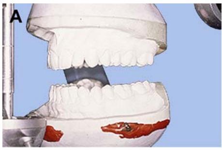
7.5.1.2. Design and Articulate the Casts. Extend the design to the attached gingiva area on the facial surface of the maxillary and mandibular casts. The mandibular cast’s lingual design should extend below the gingival margin, but not into major undercut areas. The lingual of the maxillary may be a full palate or horseshoe design. Trim the bases of the working cast as close to the design cast as possible. This will facilitate the flasking process later. Articulate the working casts using the bite registration provided (Figure 7.3-A).
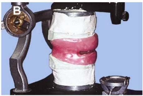
7.5.1.3. Wax Up the Appliance. Apply a uniform 2 to 3 mm thickness of baseplate wax to the design of the maxillary and mandibular cast. Fill the interocclusal space between the maxillary and mandibular arches from the first premolar to the second molar. This will leave an opening in the anterior area from canine to canine (Figure 7.3-B).
7.5.1.4. Flasking.
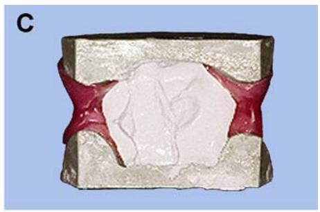
7.5.1.4.1. Because of the vertical height of the wax-up, flasking must be accomplished in a jumbo flask or two maxillary flasks combined. When using two maxillary flasks, combine two lower sections with one center section between them. Half-fill the center and lower section of the flask with flasking stone. Adapt the flasking stone into the tongue space of the wax-up and then submerge the wax-up into the flask covering the entire wax up with stone (Figure 7.3-C).
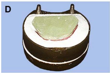
7.5.1.4.2. Smooth the surface of the lower half flasking before the stone sets completely and then apply separator to the stone (Figure 7.3-D)
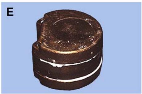
7.5.1.4.3. Mix the flasking stone for the upper half flasking. First, fill the areas around the cast. Then fill the remaining lower flask section with stone and invert it onto the lower half flasking. Excess stone should be visible between the lower and upper portions of the flask to ensure the flask is full (Figure 7.3-E). Allow the stone to set before proceeding to boilout.
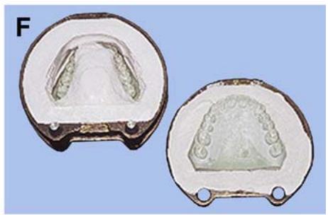
7.5.1.5. Boilout. Place the flask in boiling water for 5 minutes to soften the wax, but not melt it into the stone. Separate the flask and remove as much wax as possible. Place the mold back into boiling water to remove the remaining wax. Scrub and rinse the mold thoroughly to remove all residues (Figure 7.3-F). Apply a runny mix of separator to the mold while it is still warm. Then tip the mold on end to allow excess separator to drain.
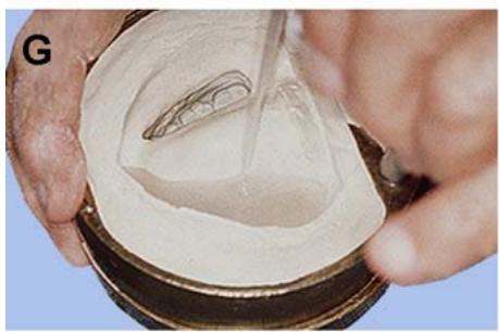
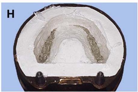
7.5.1.6. Packing and Curing. Use a soft heat cured acrylic for the appliance. The acrylic is soft when warm and hardens as it cools. This allows the appliance to flex over the contours of the oral cavity without any other retention devices. Mix the material according to the manufacturer’s directions and pour it into the lower half mold (Figure 7.3-G). Trial pack the mold several times to be sure it is densely packed (Figure 7.3-H). Place the mold into a flask carrier and cure it according to the manufacturer’s directions.
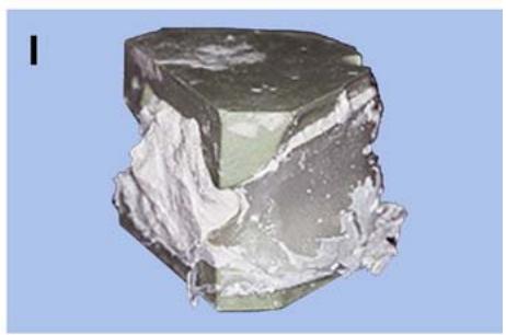
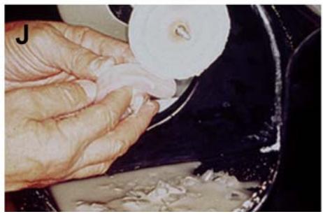
7.5.1.7. Deflasking and Finishing. Remove all stone from around the cast, leaving the appliance in place (Figure 7.3-I). Place the cast in warm water to soften the acrylic and then gently remove the appliance from the cast. Be careful because the material is more susceptible to tearing when it is in a softened state. Before finishing, soak the appliance in cold water to keep the acrylic hard while grinding on it. Smooth any rough areas and trim the appliance to the design line. Pumice and polishas usual (Figure 7.3-J).
Figure 7.3. Sleep Apnea Appliance.
natural_image
Close-up of dental model showing upper and lower jaw teeth with a red mark on the lower jaw (no text or symbols visible)
natural_image
Close-up of a dental mold with pink and white gum tissue, mounted on a metal stand (no text or symbols visible)
natural_image
3D model of a dental implant with red and white cavities, no visible text or symbols
natural_image
Cross-sectional view of a dental implant or mold with a green mesh and metallic fittings (no text or symbols visible)
natural_image
Close-up of a dark, textured cylindrical object with white markings, against a plain blue background (no text or symbols visible)
natural_image
Two dental mold cavity models with metallic surfaces and no visible text or symbols
natural_image
Close-up of hands using a tool to apply a white substance into a container (no visible text or symbols)
natural_image
Cross-sectional view of a dental implant or mold cavity (no text or symbols visible)
natural_image
3D rendered mineral specimen with translucent green and white regions against a light blue background (no text or symbols)
natural_image
Close-up of hands using a white plastic bag to apply food in a black frying pan (no visible text or symbols)
natural_image
Dental panoramic scan showing upper and lower teeth (no text or labels visible)
¶ 7.6. Surgical Splints
7.6.1. Types of Splints. A splint is an appliance, either rigid or flexible, used to immobilize displaced or movable dentition. In the treatment of certain types of jaw fractures, the oral surgeon first reduces the fracture by bringing the displaced bone segments into normal alignment and then fixes them in position by the method best suited to the patient’s needs. Later, when healing of the fragments has progressed sufficiently, the fixation apparatus is removed and a splint may be inserted in the patient’s mouth until healing is completed. (In some instances, the splint may serve as the fixation apparatus from the beginning of treatment.)
7.6.2. Variations in Splint Design.
7.6.2.1. Splints are made in different forms to deal with the variety of problems encountered in treatment. The dentist will prescribe the requirements the splint must satisfy. The dental technician must have a broad knowledge of the principles involved in splint fabrication so the basic technique can be modified to meet any of these requirements.
7.6.2.2. Splints can be made of acrylic resin or cast metal. Those made of metal are less bulky than those made of acrylic resin. One advantage of an acrylic resin splint is that it is radiolucent. Periodic radiographs can be made through it to check the progress of healing without removing the splint from the patient’s mouth. This paragraph covers the fabrication of one simple case of each type, including examples of modifications.
7.6.3. Fabricating an Acrylic Resin Fixation Splint (Figure 7.4)
7.6.3.1. Impressions and Casts. The dentist will furnish alginate impressions of both dental arches. Carefully and completely rinse the impressions of all saliva and debris and then disinfect. Remove the excess moisture with a blast of air and pour the master casts in artificial stone. Original master casts are never used as working casts. If the splint is to be used for fixation of a fracture case and the fracture has not been reduced (because the patient’s bone fragments have not been realigned), section the master cast at the line or lines of fracture and reassemble the fragments in proper position and occlusion. Then make a duplicate cast for this purpose.
7.6.3.2. Design.
7.6.3.2.1. Mark a line along the junction of the middle and incisal (or occlusal) thirds of all teeth on their facial and lingual surfaces (Figure 7.4-A). This line represents the superior border of the prosthesis. If the vertical overlap of the maxillary anterior teeth is excessive, the line may have to be placed more gingivally on the facial surfaces.
7.6.3.2.2. Make a line on the facial surface of the cast, halfway between the gingival border of the teeth and the buccal sulcus. Mark another line on the lingual surface of the cast halfway between the gingival border of the teeth and the floor of the mouth. These lines represent the inferior border of the prosthesis.
7.6.3.2.3. Complete the outline of the design by marking vertical lines on the facial surface of the last molar on each side of the arch.
7.6.3.3. Hinges. The splint consists of a lingual and two facial sections joined by wire hinges running distal to the last molar on each side.
7.6.3.3.1. On each side, closely adapt 14-gauge, half-round wire to the distal surfaces of the last molar to be included in the splint (Figure 7.4-B). Keep the wire as close as possible to the gingiva without impinging on soft tissue.
Figure 7.4. Acrylic Resin Fixation Splint.
natural_image
Anatomical illustration of a humandentitionary jaw (no text or labels visible)
Duplicate master cast
natural_image
Anatomical illustration of a human dental arch with teeth and jawbone (no text or labels)
Wire adapted
natural_image
Dental X-ray image showing upper and lower teeth with dental implants (no text or labels visible)
Splint waxed
natural_image
Anatomical illustration of a human dental arch (no text or labels visible)
Button waxed
natural_image
Cross-sectional view of a dental implant or mold component (no visible text or symbols)
Lower half flask
natural_image
Cross-sectional medical scan image showing a dental implant or cavity (no visible text or labels)
Wax-up tinfoiled
natural_image
Medical scan image showing a cross-sectional view of teeth and jawbone (no text or labels visible)
Splint finished and polished
natural_image
Dental model of a human jaw with visible teeth and jawbone structure (no text or labels)
Finished splint on cast
7.6.3.3.2. Carry each wire around onto the facial and lingual surfaces of the teethas far forward as the center of the next tooth. Bend the ends of the wire laterally at right angles and cut off the excess, leaving about 12 mm jutting out facially and lingually. Do not adapt the wires too close to the facial and lingual surfaces of the teeth. There should be aslight space (about 1 mm) that will allow the splint material to flow around the wires, embedding them.
7.6.3.3.3. Tack the hinges into position with sticky wax.
7.6.3.4. Wax-Up and Flasking.
7.6.3.4.1. Apply two thicknesses of baseplate wax, sealing their edges to the design on the cast. Make the outer surface flat and smooth (Figure 7.4-C).
7.6.3.4.2. Grind the incisal or occlusal thirds of the stone teeth flat and even with the top surface of the wax. Cut out the artificial stone from under the wire hinges on each side to allow the wires to be pulled with the top half of the flask when the flask is opened (to eliminate wax).
7.6.3.4.3. Attach a 6 mm wax button to the facial surface at the midline (Figure 7.4-D)
The completed splint will be section ed through the button vertically. The dentist will use the
halves of the button as anchors for wiring the two facial sections together in the mouth. Additional undercut buttons or metal lugs can be placed in convenient areas to provide anchor points for intermaxillary traction.
7.6.3.4.4. Trim any excess wax at the borders to the previously drawn design. The edges should be sharp, definite, and at right angles to the cast. Fill any edentulous areas with wax. Half-flask the case in the usual manner for processing acrylic resin (Figure 7.4-E).
7.6.3.4.5. If using translucent acrylic resin, tinf oil the wax-up well (Figure 7.4-F)
(Some types of translucent acrylics suggest the use of tinfoil rather than tinfoil substitute to achieve a clear product.) Consult the manufacturer’s directions for the type of acrylic used.
7.6.3.4.6. Full flask the case, using the stone cap method to help deflasking after the case has been processed.
7.6.3.5. Packing, Processing, and Finishing.
7.6.3.5.1. Eliminate the wax by immersing the flask in boiling water for 5 minutes. Open the flask and remove all the wax by flushing as usual. Apply tinfoil to the cast.
7.6.3.5.2. Pack acrylic resin and process as usual. After bench cooling for 30 minutes, immersethe flask in cold water for 15 minutes.
7.6.3.5.3. Deflask and recover the splint.
7.6.3.5.4. Finish and polish the prosthesis as usua l. Use an acrylic resin finishing bur to create aslight groove around the base of the button at its point of attachment.
7.6.3.6. Sectioning the Splint.
7.6.3.6.1. Section the splint faciolingually at the midline of the facial segment and mesiodistally through the center of each edentulous space (Figure 7.4-G). Use either a thin disc or a jeweler’s saw.
7.6.3.6.2. Carefully trim the gingival border to adapt the splint to the duplicate working cast (Figure 7.4-H)
7.6.4. Fabricating an Edentulous Fixation Splint (Gunning Splint)
7.6.4.1. Edentulous fixation splints are used to immobilize fractured ed entulous maxillae and mandibles. They are als o used when the patient does not have com plete dentures that can be modified for use as a fixation splint.
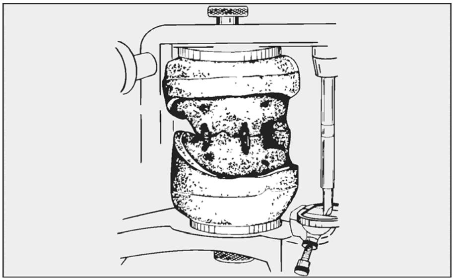
7.6.4.2. A splint consists of record bases and occlus ion rims processed in acrylic resin (Figure 7.5)
First, the dentist modifies the rims to match the patient’s occlusal vertical dimension by orienting the wax rims in centric relation. Next, a V-shaped notch is carved into the occlusal surface of one of the occlusion rims. A V-shaped projection is then added to the opposing occlusion rim to provide a means of positively orienting the two edentulous arches. This notch arrangement helps maintain the fractured maxillae and mandible in proper centric relation and occlusal vertical dimension until healed. The anterior segments are left open so the patient can eat more easily and expel food in the event of choking.
7.6.4.3. The splints are processed by using the same procedures as acrylic resin com plete dentures. At the direction of the dentist, bend several wire hooks and attach them to the splint by using autopolymerizing acrylic resin. The wires are used with rubber elastics for intermaxillary fixation.
Figure 7.5. Gunning Splint.
natural_image
Technical line drawing of a dental implant device with labeled components (no text or symbols)
¶ 7.7. Specifications and Laboratory Procedures for Cast Arch Bars
7.7.1. An arch bar is a splint-like device used to hold jaw fragments together in proper alignment in a patient’s mouth. The need for such a device most often arises because of injury.
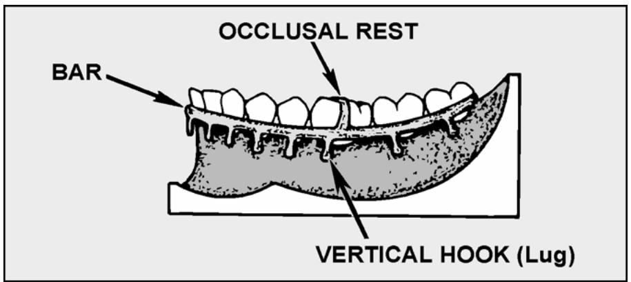
7.7.2. A cast arch bar is a band of metal cast to fit around a dental arch, against the facial surfaces of remaining teeth. The bar has a number of lugs that protrude from its gingival border.
7.7.3. Arch bars are frequently used in pairs, one maxillary and one mandibular. Each bar is wired in place on an arch, using remaining natural teeth for anchorage. The two bars are then held together by rubber bands or heavy duty, silk thread. The idea is not only to hold a jaw’s fragments together with the bar, but to stabilize a broken jaw against one that is not broken. This inter-arch stabilization is essential if the broken jaw is to heal in good occlusion with its opponent. The purpose of these specifications is to standardize construction procedures so the resulting arch bars will fulfill the requirements oforal surgeons and best serve the needs of the patient.
7.7.4. Because many patients are hospitalized while awaiting the construction of the bars, construction procedures should be given top priority and the fabrication expedited by all reasonable means.
¶ 7.8. Impressions and Jaw Relationship Record for Cast Arch Bars
As always, the dentist is obligated to make the best impression possible. Making an impression of a patient’s fractured jaw is difficult. Such patients are in pain and have extreme difficulty opening their mouths wide enough to accommodate impression trays. When appropriate, an interocclusal record should accompany the case.
¶ 7.9. Construction Specifications for Cast Arch Bars
7.9.1. Bar.
7.9.1.1. The bar must have adequate, uniform thickness and width toresist distortion or breakage.
7.9.1.2. The gingival-occlusal width should equal 2 to 2 1/2 mm with a faciolingual thickness 1 to 1 1/2 mm. Use the larger dimensions when the arch bar will be fabricated using gold alloys. Base metal alloy is stronger and can be a little less bulky. Build the bar so it has a flat surface in contact witheach tooth. The bar will traversethe area on the facial surfaces of the crowns between the contact points and the gingival tissue.
7.9.1.3. The gingival edge of the bar should come to within 0.5 to 1 mm of the midfacial surface junctions of gingivae and teeth (Figure 7.6)
Hopefully, the occlusal border of the b ar will be at least 1 mm gingival to the contact points of the teeth to allow easier wiring and better jaw fragment stabilization.
Figure 7.6. Cast Arch Bar Seated on the Working Cast.
text_image
OCCLUSAL REST
BAR
VERTICAL HOOK (Lug)
7.9.1.4. Extend the bar around the arch in a relativ ely straight line with no interproximal contouring or festooning. Relie ve the interproximal areas enough to prevent pressure on interproximal papillae. Arch bars that extend into interproximal areas are very difficult to ligate to teeth because there is not enough working room.
7.9.2. Occlusal Rests. Place at least one occlusal rest on each side of the arch. The rests are essential to help position and support the bar in the patient’s mouth. The rest may be placed on a buccal groove or on a marginal ridge area, depending on where space is available. Make absolutely sure the rests do not prevent opposing natural teeth from making contact in MI.
7.9.3. Vertically Oriented Traction Lugs (Hooks)
7.9.3.1. There should be 1 to 1 1/2 mm clearance between the inner surface of the lug and the gingival tissue under it. In this raised condition and paralleling the gingival surface, the dentist should have notrouble wrapping ligature material around opposing lugs. Also, the lug will not stab into the patient’s cheek.
7.9.3.2. About one lug per tooth is needed. Position the lugs in the centers of anterior teeth and premolars, favoring the mesial 1/3 of molar teeth. Place a lug at the distobuccal corner of the most posterior tooth to help maintain the ligature wire in proper position during placement of the bar.
7.9.3.3. The average length of a lug from the arch bar to the tip should be 3 to 4 mm. The lug should be cylindrical with a bead or ball on the tip. No sharp edges or corners should be present to cut ligature material. The lug should be between 1 and 1 1/2 mm in diameter and the junction between the bar and the lug should be of sufficient bulk to eliminate the possibility of breakage when ligature traction is applied.
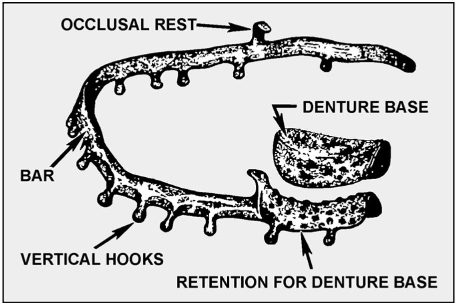
7.9.4. Denture Base (Figure 7.7)
7.9.4.1. Sometimes, a patient does not have enough natural teeth remaining in an arch to stabilize broken jaw segments with a conventional cast arch bar. Therefore, a denture base that occludes with opposing teeth can be added to one or more sections of an arch bar to provide additional stabilization. Plan for a space between the proximal face of the denture base and the adjacent tooth. The space permits passage of a ligature wire that fastens the arch bar to the tooth.
7.9.4.2. All facially located flanges should be 3 to 4 mm short of the sulcus. The lingual flange of a mandibular denture base should be 2 to 3 mm short of the lingual sulcus when the floor of the mouth is active. For those denture base additions that might cover the palate, the posterior border of the palate should be short of the vibrating line. Do not bead or scrape the cast for a posterior palatal seal.
Figure 7.7. Cast Arch Bar With Denture Base Modification.
text_image
OCCLUSAL REST
DENTURE BASE
BAR
VERTICAL HOOKS
RETENTION FOR DENTURE BASE
¶ 7.10. Laboratory Procedures for Cast Arch Bars
7.10.1. Pouring and Designing Casts. Pour casts in vacuum spatulated dental stone. Either the dentist draws the design on the cast or the technician transfers the design from the prescription to the cast.
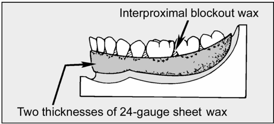
7.10.2. Blocking Out and Relieving the Master Cast (Figure 7.8)
7.10.2.1. Place 2 thicknesses of 24-gauge wax, 6 to 8 mm wide strips, over the cast’s facial attached gingivae, from the distal of the most posterior tooth on one side of the arch to the distal of the most posterior tooth on the opposite side. Orient the occlusal border of the wax about 0.5 mm occlusal to the junction of tooth and gingivae on each tooth’s midfacial surface. Seal the edges of the wax in place securely.
7.10.2.2. Block out the interproximal area by overfilling it slightly with blockout wax. Be sure the blockout wax extends from the occlusal edge of the relief wax to the occlusal or incisal aspects of the teeth to prevent the bar from impinging on the soft tissue in the interproximal areas.
7.10.2.3. If the arch bar is going to have an attached denture base, relieve the cast as prescribed by the dentist (under the proposed denture base retention grid)
7.10.3. Duplicating the Master Cast. Duplicate the master cast in refractory material and wax dip the cast following standard procedures.
Figure 7.8. Blockout and Relief of the Master Cast.
text_image
Interproximal blockout wax
Two thicknesses of 24-gauge sheet wax
7.10.4. Waxing.
7.10.4.1. Make a gold arch bar a little bulkier than one made from chrome alloy. Make the bar from 8-gauge half-round wax. Before waxing, scrape the edges to eliminate the sharpness. As previously mentioned, the occlusogingival width should equal 2 1/2 mm and the wax shape about 1 1/4 mm thick.
7.10.4.2. With the flat side toward the teeth, adapt the wax shape to the facial surfaces. Make the gingival edge of the wax coincide with the occlusal edge of the sheet wax relief, as represented on the refractory cast. Make the vertical lugs of 18 gauge round wax shapes.
7.10.4.3. Dip the tips of the lug patterns in molten wax to form small balls on the ends. Position the shapes relative to tooth surfaces as previously described. Do not smash the wax preforms while they are being placed. Lugs should extend about 3.5 mm from the gingival edge of the bar toward the sulcus. Ensure the waxing of occlusal rests and denture base areas follows common RPD guidelines.
7.10.5. Spruing, Investing, and Casting. Sprue, invest, and cast the pattern in base metal alloy or gold, using the same procedures as those for RPDs.
7.10.6. Polishing the Casting. Do not cut the sprues off until polishing procedures are almost done. If the casting is not supported in some way, it will bend.
¶ Section 7B — Face Form Cast (Moulage)
¶ 7.11. Custom-Fitted Mask
Because their faces have unusual shapes, some aircrew members who use oxygen masks during flying duties cannot wear the standard sizes. These people require a custom-fitted mask. The flight surgeon will determine when this is necessary and will request the dental facility to fabricate a face form cast. From a prosthodontic viewpoint, face form casts can be essential in making maxillofacial prostheses. The face form cast must be (1) made of artificial stone, (2) free of voids and nodules, and (3) an accurate reproduction of the face. It must cover the entire facial area from at least 2 inches above the eyebrows to at least 2 inches below the chin and slightly anterior to the tragus of the ear.
¶ 7.12. Procedures for Making a Face Form Cast
7.12.1. Before beginning these procedures, explain the complete operation to the patient in detail. Specify that he or she will have to breathe through straws placed in the nostrils. Emphasize the feeling of enclosure and the slight difficulty in breathing that might be encountered. Constant reassurance during the entire procedure will help the patient avoid the feeling of panic.
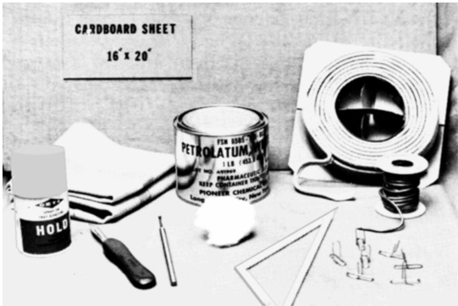
7.12.2. This procedure must be completed in a minimum of time and can be accomplished best by thorough preplanning. All equipment and materials must be laid out for immediate availability (Figure 7.9). Items required are a 16- by 20-inch cardboard sheet, cloth towel, petrolatum, rope caulking, alginate spray adhesive, knife, large round burnisher, bulk, cotton, large diameter flexible straws, paper clips, and soft wire solder.
Figure 7.9. Required Equipment and Materials.
text_image
CARDBOARD SHEET
16" x 20"
PETROLATUM
1 LB (453.8 kg)
PHARMACEUTICAL
KEEP CONTAINER TONE
PIONEER CHEMICAL
LONG
HOLD
7.12.3. Working together during the impression phase, the dentist and assistant will:
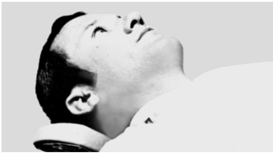
7.12.3.1. Place the patient in a horizontal position and cover with plastic apron to protect his or her clothing (Figure 7.10)
Figure 7.10. Patient Reclined in a Horizontal Position.
natural_image
Black-and-white portrait of a person in profile, looking upward (no text or symbols visible)
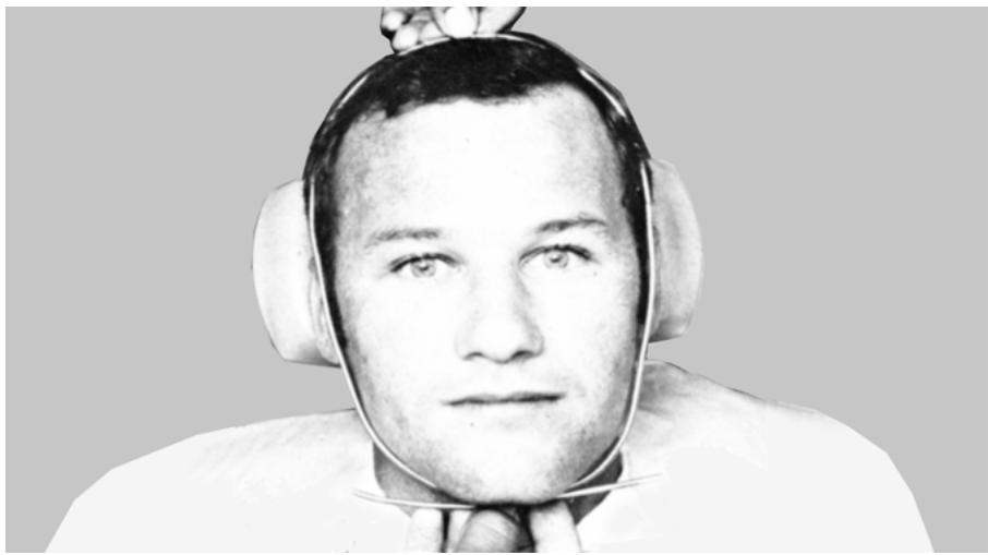
7.12.3.2. Bend a length of pliable wire solder around the patient’s face to form an outline (Figure 7.11)
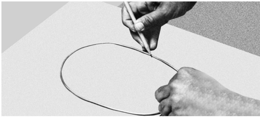
7.12.3.3. Center the molded wire on the 16- by 20-inch cardboard sheet and trace the inner circumference with a pencil (Figure 7.12)
Figure 7.11. Measuring Facial Diameter With a Length of Wire Solder.
natural_image
Black-and-white portrait of a man wearing a head-mounted medical device (no visible text or symbols)
Figure 7.12. Tracing Facial Diameters on a Cardboard Sheet.
natural_image
Close-up of hands drawing a circle on paper, no text or symbols visible
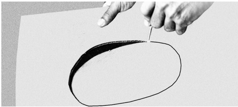
7.12.3.4. Cut and remove the area within the outline from the cardboard sheet (Figure 7.13)
Figure 7.13. Cutting the Facial Outline From the Cardboard.
natural_image
Hand drawing a black oval shape with a fine brush tip, no text or symbols present
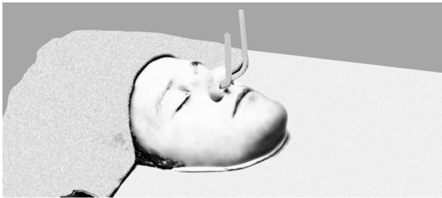
7.12.3.5. Place the cardboard sheet over the patient’s face. The cardboard should fit loosely. If necessary, trim it to prevent distortion of the facial tissues. Support the cardboard from underneath, using folded cloth towels. Fill the space between the cardboard and tissue by gently adapting rope caulking cord (Figure 7.14).
7.12.3.6. Fold a dampened towel and drape across the patient’s forehead to keep the impression material out of the patient’s hair (Figure 7.14)
Generously coat all exposed hair (eyebrows, eyelashes, and sideburns) with petrolatum (vaseline).
7.12.3.7. Cut one end of each of two straws approximately 1 inch from the flexible portion. Insert these ends gently into the nostrils. Carefully pack a well lubricated (vaseline) piece of bulk cotton into each nostril around the straws for support (Figure 7.14). A large ball-shaped burnisher is an excellent packing instrument. Be sure to have the patient close his or her mouth and breathe through the straws to determine breathing tolerance.
Figure 7.14. Patient Prepared for the Impression.
natural_image
Black-and-white photo of a person lying down with a medical instrument inserted, no visible text or symbols
7.12.3.8. Prepare three batches of regular set alginate. Measure the powder and liquid for each batch and place it in separate containers. Use three separate mixing bowls. Measure cold tap water for each batch and place in a separate bowl. All three batches require approximately 8 scoops of alginate powder.
7.12.3.9. The first mix should be thinner than the subsequent mixes and its water-to-powder ratio should be 2 to 1. The two succeeding mixes should have a ratio of 1 1/2 to 1.
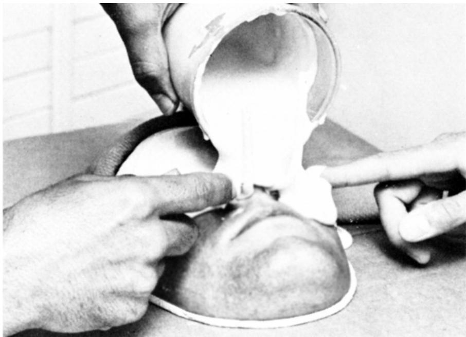
7.12.3.10. Pour the first mix (thin) over the facial tissues while the dentist distributes it with the fingers to prevent bubble formation (Figure 7.15). Prepare second and third mixes while the first mix is being applied. Apply this thicker alginate with spatulas to build up a layer approximately 3/8 inch thick.
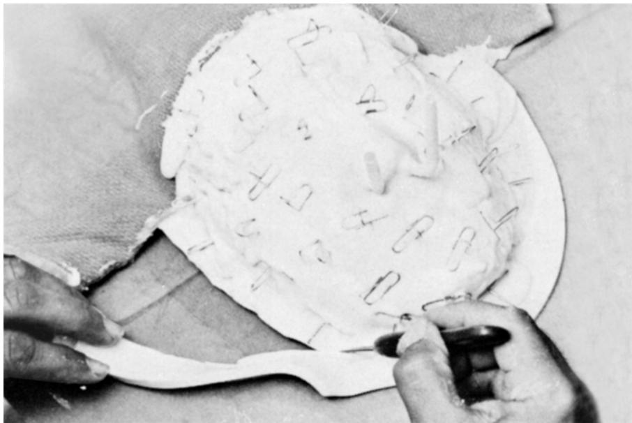
7.12.3.11. While the alginate is still tacky, insert bent paper clips or unfolded 4 by 4 gauze pads into it (Figure 7.16)
7.12.3.12. Trim the set alginate away leaving a minimal margin of approximately 1/2 inch (Figure 7.16)
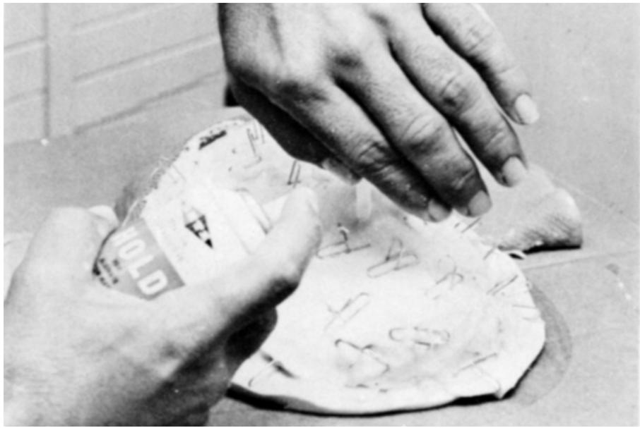
To increase the adhesion between the alginate and supporting stone, spray the surface of the alginate with an adhesive material. Shield the ends of the straws to prevent inhalation of the spray (Figure 7.17).
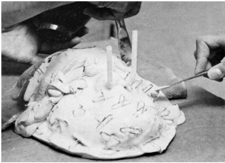
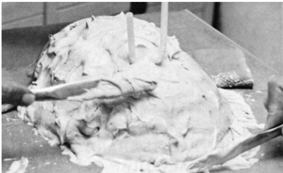
7.12.3.13. During the next procedure, the assistant prepares a flowable mix of fast setting stone. Use slurry water concentrate to shorten the setting time of stone. Apply the stone with spatulas to cover all of the exposed impression material to a depth of 1/2 inch (Figures 7.18 and 7.19). Several mixes of stone will be required.
Figure 7.15. Applying Alginate Mix to the Face.
natural_image
Medical procedure image showing hands performing a procedure on a patient's head (no visible text or symbols)
Figure 7.16. Trimming Excess Alginate After Completion of the Impression.
natural_image
Close-up of hands cutting a white paper with engraved symbols (no readable text or numbers)
7.12.3.14. When the heat of crystallization can be felt in the stone, remove the towel from the forehead and release the impression by pulling it away from the forehead first.
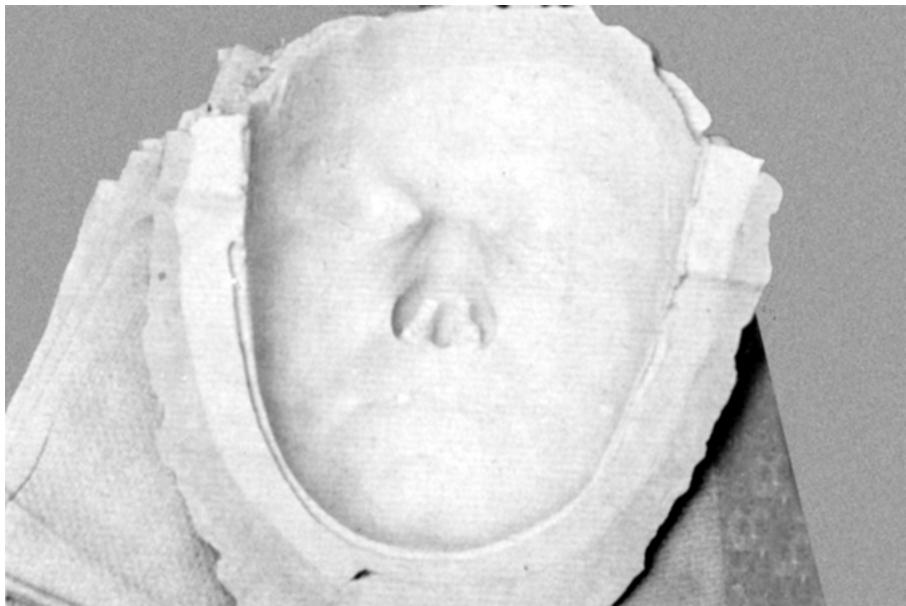
7.12.3.15. The impression is ready for pouring (Figure 7.20)
Remember that the stone support is fragile, especially around the nose. Support the impression during pouring by using folded towels on the side of the stone.
7.12.3.16. Make a soupy mix of stone and cover the entire surface of the alginate with a thin layer. Apply subsequent mixes of regular consistency to build approximately a 3/4 inch thickness of stone over the impression.
Figure 7.17. Shielding Straws While Spraying Adhesive for Alginate.
natural_image
Close-up of hands using a handprint to cut out dough on a surface (no visible text or symbols)
Figure 7.18. Applying Supporting Stone to the Alginate Impression.
natural_image
Close-up of a medical procedure on a patient's head, showing surgical instruments and tissue (no visible text or symbols)
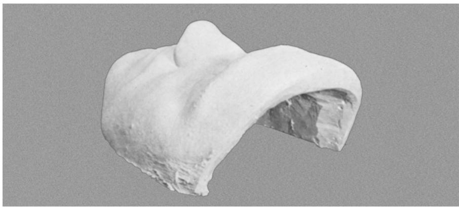
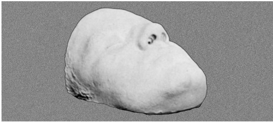
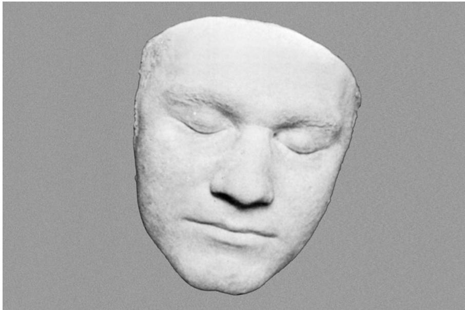
7.12.3.17. Allow the stone to set approximately 1 hour. Separate the cast and trim the edges to prepare it for shipment (Figures 7.21, 7.22, and 7.23).
Figure 7.19. Supporting Stone Layer Completed to a Depth of 1/2 Inch.
natural_image
Close-up of hands using chopsticks to spread a large, irregularly shaped food item on a metal surface (no visible text or symbols)
Figure 7.20. Looking Into the Completed Impression.
natural_image
Close-up of a sculpted human head with a smooth, rounded surface and visible teeth (no text or symbols)
Figure 7.21. Oblique View Showing Cast Thickness.
natural_image
Close-up of a white, irregularly shaped, bone-like object with a hollow interior (no text or symbols visible)
Figure 7.22. Lateral View of the Face Form Cast.
natural_image
Close-up of a rough, irregularly shaped stone or mineral specimen (no text or symbols visible)
Figure 7.23. Frontal View of the Face Form Cast.
natural_image
Close-up of a sculpted face with closed eyes and horizontal lines, resembling a stylized human head or mask (no text or symbols visible)
¶ Section 7C — Cleft Palates and Obturators
¶ 7.13. Cleft Palate
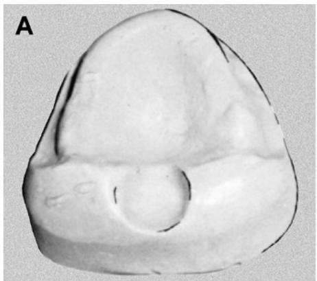
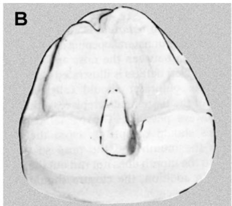
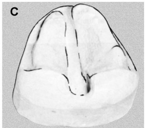
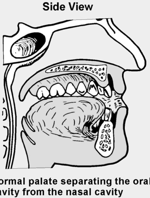
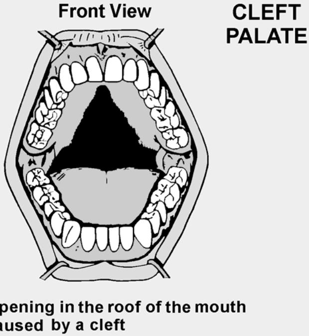
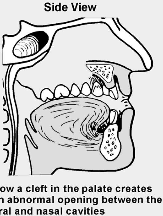
A cleft palate is a defect in the roof of the mouth and the nasal cavity. Clefts may be confined to the soft palate (Figure 7.24-A), or they may include all or part of the hard palate (Figure 7.24-B). Palatal clefts may extend anteriorly to include clefts of the anterior alveolar ridge (Figure 7.24-C). If a cleft is present at birth, it is called “congenital.” If it is a result of injury, disease, or surgery, it is called an “acquired cleft.”
Figure 7.24. Cleft Palates.
natural_image
Close-up of a smooth, irregularly shaped object with a central circular feature and two curved ridges (no text or symbols visible)
Cleft of the soft palate
natural_image
Cross-sectional medical scan image showing a cross-section of a biological structure (no visible text or labels)
Cleft of the soft palate and part of the hard palate
natural_image
Anatomical illustration of a brain cross-section (no labels or text)
Extensive cleft involving the soft palate, hard palate, and alveolar ridge
¶ 7.14. Obturator
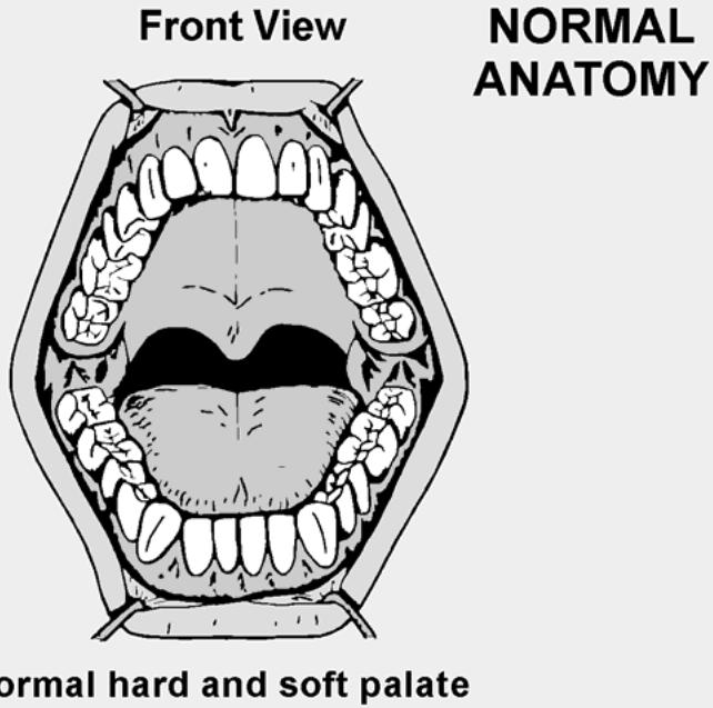
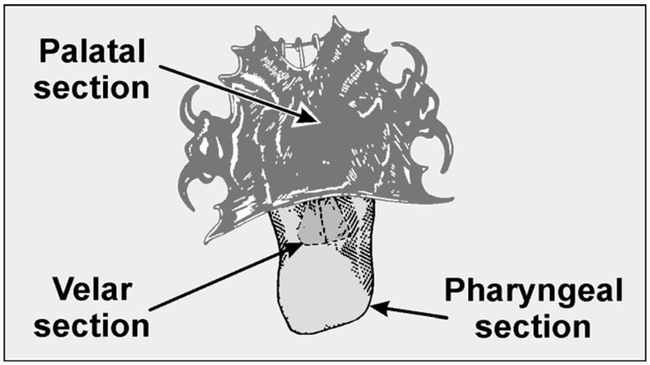
An obturator is a prosthetic device that closes the unnatural opening and reestablishes the separation between the nose and mouth. The anatomy of cleft defects is illustrated in Figure 7.25. Ideally, the obturator should fully restore the function of the tissue it replaces, although this is not always possible. The palatal part of the prosthesis should completely close the opening between the mouth and the nose so food taken into the mouth does not enter the nasal cavity. In addition, the closure should help restore distinct speech. An obturator usually has three functional sections (Figure 7.26), depending on the size and extent of the cleft:
7.14.1. Palatal Section. This is the base that covers the hard palate and part of the soft palate. When natural teeth remain, it carries clasps for retentive purposes.
7.14.2. Pharyngeal Section or Bulb. This is the roughly spherical section that extends into the pharynx. It is formed and contoured so the pharyngeal muscles, by contracting, close off the mouth and pharynx from the nasal cavity during swallowing. When the obturator base is well retained and the bulb is small and light, the bulb is made from a solid piece of plastic. If the opposite conditions prevail, a hollow bulb is made instead.
7.14.3. Velar Section. This is the intermediate part that supports the bulb and attaches to the base.
¶ 7.15. Retention Factors
7.15.1. Developing adequate retention for the prosthesis can be easy or difficult, depending on the number, shape, and distribution of remaining natural teeth; strength and direction of muscle pull; amount of peripheral seal that can be obtained; extent of tissue coverage; presence of scar tissue; and size and weight of the pharyngeal section.
7.15.2. A principle that is always used in obturator design is to obtain all of the tissue coverage the patient can tolerate. Undercuts are used where possible, even if it is necessary to extend the base into the nasal cavity. Scribing a bead line in the cast around the periphery of the design usually improves peripheral seal. The dentist knows which tissues are soft and which are hard and will prescribe the exact borders of the prosthesis as well as the depth and position of any beading that is to be done.
Figure 7.25. Normal and Cleft Palate Anatomy Contrasted.
A
text_image
Front View
NORMAL
ANATOMY
normal hard and soft palate
B
text_image
Side View
normal palate separating the oral cavity from the nasal cavity
C
text_image
Front View
CLEFT
PALATE
opening in the roof of the mouth
nused by a cleft
D
text_image
Side View
how a cleft in the palate creates
an abnormal opening between the
ral and nasal cavities
Figure 7.26. Parts of the Obturator.
text_image
Palatal
section
Velar
section
Pharyngeal
section
¶ 7.16. Fabrication Procedures
The palatal section of the prosthesis is usually made first with an attachment on its posterior border to which the pharyngeal portion is later added. The fabrication process is shown below (and in Figure 7.27):
Figure 7.27. Obturator Fabrication.
natural_image
3D medical scan of a dental model showing upper and lower teeth (no text or labels visible)
Master cast
natural_image
Dental X-ray image showing upper and lower teeth (no text or labels visible)
Master cast surveyed
natural_image
3D rendered model of a human dental model showing upper and lower teeth (no text or labels visible)
Refactory cast
natural_image
Medical scan image showing a dental arch with multiple teeth and a metallic fixation device (no text or labels visible)
Wax pattern
natural_image
Medical scan image showing a dental arch with multiple teeth and jawbone structures (no text or labels visible)
Finished casting
natural_image
Medical CT scan image of a dental arch showing teeth and jawbone structure (no text or labels visible)
Modeling plastic attached
natural_image
3D medical scan of a human organ (likely liver or heart) showing internal structures and anatomical features, labeled 'G' in the top-left corner.
Pharyngeal impression
natural_image
Microscopic view of a biological or material sample with irregular, textured structures (no visible text or symbols)
Finished obturator
7.16.1. The dentist furnishes a preliminary impression and prescribes the outline for an individual impression tray and the material from which it is to be made.
7.16.2. Final impressions must be handled with a great deal of care. They represent painstaking work by the dentist as well as discomfort and fatigue for the patient. When boxing and pouring one of these impressions, the plaster and pumice method gives you the most control with the least potential for distortion. See Volume 1, Chapter 7, for guidance on the plaster pumice method.
7.16.3. Pour an artificial stone master cast as soon after the dentist makes the impression as possible. Duplicate the master cast before surveying. The duplicate can be used as a backup in case of accident (Figure 7.27-A).
7.16.4. Survey the master cast. Place the design for the prosthesis on the master cast in the same way as for a conventional RPD (Figure 7.27-B).
7.16.5. Block out tooth and soft tissue ridge undercuts in the usual manner. Place relief wax over edentulous ridge areas where indicated. Block out the cleft defect with modeling clay.
7.16.6. Duplicate the (blocked out) master cast in refractory investment (Figure 7.27-C)
(Make another duplicate of a blocked out master cast in dental stone for framework fitting purposes.)
7.16.7. Wax the retainers and connectors, using the same methods as for a conventional RPD framework. Wax in a strong retention loop to retain and support the pharyngeal section of the obturator (Figure 7.27-D).
7.16.8. Invest and cast the pattern. Finish and fit to a duplicate master cast. Final polish the casting (Figure 7.27-E).
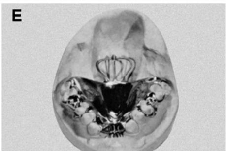
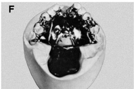
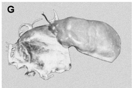
7.16.9. The dentist will make sure the framework fits the patient’s mouth, take modeling plastic and attach it to the retention loop, soften the modeling plastic, and place the entire apparatus in the patient’s mouth. He or she will direct the patient to go through a series of movements to mold the modeling plastic into a bulb shape. Sometimes the dentist will coat the modeling plastic bulb with a secondary impression material (low fusing wax) to pick up fine details (Figure 7.27-F and -G)
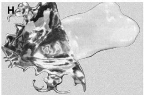
7.16.10. Process the pharyngeal section in acrylic resin (Figure 7.27-H)
When the bulb portion is going to be solid, flask, pack, and process it in the usual manner. If the dentist has ordered a hollow bulb, special processing techniques are required. For descriptions of techniques used to make hollow obturator bulbs, consult the following articles:
7.16.10.1. Matalon, V. and LaFuente, H.: A Simplified Method for Making a Hollow Obturator. Journal of Prosthetic Dentistry, Vol 36: p. 580, Nov 76.
7.16.10.2. Chalian, V.A. and Barnett, M.O.: A New Technique for Constructing a One Piece, Hollow Obturator After Partial Maxillectomy. Journal of Prosthetic Dentistry, Vol 28: p. 448, Oct 72.
¶ Section 7D — Custom Earpiece
¶ 7.17. Introduction
7.17.1. A custom earpiece is an acrylic device fabricated to custom fit the patient’s ear and used to deliver sound to the ear by way of a hollow tube. The increase in comfort of a custom earpiece versus a standard earpiece is considerable and easily justifiable when one considers the amount of time personnel, suchas aircrews or air traffic controllers in critical situations, spend depending on precise reception.
7.17.2. Traditionally, many different types and models of standard earpieces, which are relatively expensive and usually fit poorly, are used in the work environment. One standard model consists of several rubber bulbs from which the user selects the best fit. A solution for military members is to have a custom earpiece fabricated.
7.17.3. The custom earpiece is composed of acrylic that fills the inner “C” portion of the patient’s ear and supports an earmold ring and spring located in the center of the acrylic (Figure 7.28-A). A hollow channel is located from the earmold ring to the end of the ear canal portion of the acrylic to deliver the sound. A hollow tube is then connected to the earmold ring from the radio or device that will be monitored by the operator. Paragraph 7.18 discusses the fabrication of a custom earpiece.
¶ 7.18. Fabricating a Custom Earpiece
7.18.1. Making the Impression. The dentist will make an impression of the patient’s inner “C” portion of the ear using a polyvinylsiloxanne or comparable impression material (Figure 7.28-B). The impression is then disinfected and taken to the laboratory for the fabrication process.
7.18.2. Fabricating an Alginate Mold.
7.18.2.1. Make an alginate mold of the impression. Cut any excess impression material that extends beyond the inner “C” portion of the ear (Figure 7.28-C). Cut the exterior surface of the impression material flat to create the surface where you will later place the earmold ring.
7.18.2.2. Use a standard paper cup to make an alginate mold of the impression. First, place the impression inside the cup to ensure there is at least 6 mm of clearance around the entire impression. Mix two scoops of alginate to 100 ml of water and vacuum mix for approximately 15 seconds.
7.18.2.3. Apply alginate onto the impression first to reduce the possibility of trapping air. Then pour the remaining alginate into the cup and set or sink the impression until the outer portion is flush with the top of the alginate (Figure 7.28-D).
7.18.2.4. After the alginate has set, use a small burst of air to remove the impression. Be careful—the alginate is soft and can be easily torn. Check inside to see if there are any voids or loose material that can be easily filled or removed.
7.18.3. Pouring the Acrylic Earpiece. Use clear orthodontic acrylic to fill the alginate mold and form a dense acrylic resin earpiece. Mix a 2 to 1 polymer/monomer ratio to achieve a runny mix that can be poured into the mold. The mix should be thin enough to fill all of the little intricate areas of the alginate mold. As you pour the acrylic into the cup, slightly tilt the cup in different directions so you do not trap air in some of those hard-to-reach areas. Because orthodontic acrylic shrinks abo ut 7 percent of its bulk, you need tof ill slightly above the top of the mold (Figure 7.28-E). Cure the acrylic according to the manufacturer’s directions.
7.18.4. Earmold Ring and Spring Placement.
7.18.4.1. After the acrylic has cured, remove the earpiece from the alginate mold (Figure 7.28-F)
Flatten the outer portion of the acrylic earpiece that was exposed from the alginate mold to create a surface that will accept the earmold ring. Place the ring on the flat surface in a position that allows an adequate amount of resin around the border of the ring, and then trace around the ring (Figure 7.28-G).
Figure 7.28. Fabricating a Custom Earpiece.
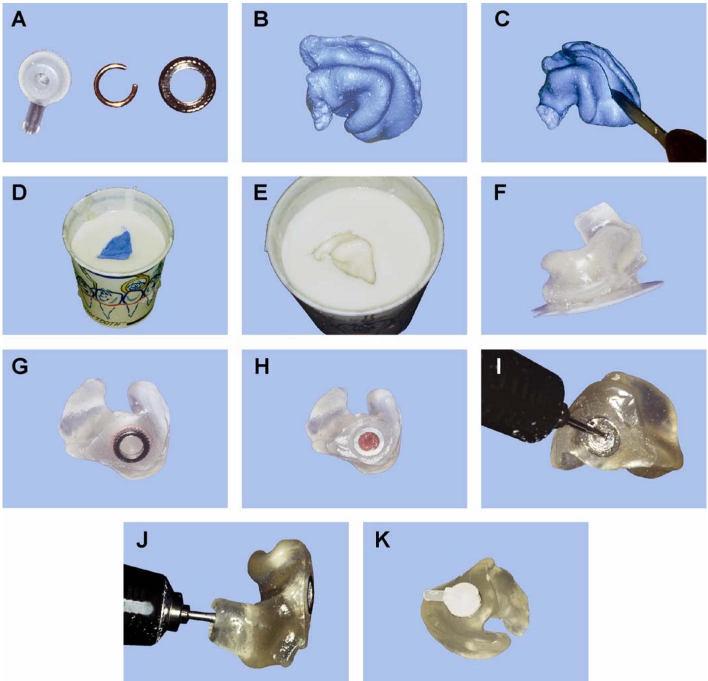
7.18.4.2. Using the outline of the earmold ring as a guide, make a hole in the acrylic so the ring will sit flush with the top of the acrylic and have approximately 1.5 to 2 mm of space around the ring.
7.18.4.3. Next, place the earmold spring into the ear mold ring. Apply a small amount of clear utility wax into the opening of the earmold ring to ensure acrylic does not fill the ring. Place the ring into the recessed area and sprinkle acrylic around the ring to seal it in place (Figure 7.28-H).
7.18.4.4. After the acrylic has cured, smooth the area around the ring with a carbide bur (Figure 7.28-I)
7.18.5. Finishing the Custom Earpiece. Use a #8 round bur to create an echo chamber under the ring (Figure 7.28-J). The chamber should be no less than 5 mm in depth and the same or slightly larger than the ring. This allows for the sound to be slightly amplified to increase the hearing ability of the person wearing the custom earpiece. With a small round bur, create a channel from the echo chamber to the end of the ear canal. Finish this sound canal by using a #6 or #8 round bur to widen the canal. Complete the custom earpiece by rounding any sharp edges. Then pumice and polish the appliance (Figure 7.28-K).
DentalTechnology.org is dedicated to preserving, teaching, and advancing the craft of dental technology.
This resource is made possible by Russellville Dental Lab, a full-service dental laboratory in Russellville, Kentucky, serving clinicians across the USA for more than 70 years.