¶ Chapter 9 — DENTAL LABORATORY EQUIPMENT IDENTIFICATION, PREVENTIVE MAINTENANCE, AND SAFETY
Reference Edition
This chapter is part of the Air Force Dental Laboratory Manual (2005) – Digitally Restored Edition.
This edition preserves the original publication while correcting OCR errors, restoring formatting, reconstructing damaged tables where necessary, and improving digital readability.
The technical content has not been rewritten, modernized, expanded, or altered.
It is provided as a professional reference. Modern instructional material is published separately throughout DentalTechnology.org.
¶ 9.1. Introduction
9.1.1. If you are a novice technician, this chapter provides guidance for identifying various kinds of common equipment. It gives instruction in routine maintenance and issues warnings about hazards of the equipment. Manufacturers routinely furnish complete maintenance and operating procedures with each new piece of equipment. If these documents are not received with the machine, contact the manufacturer and request instructions.
9.1.2. The laboratory supervisor is obligated to extract detailed, in-house operating maintenance and safety instructions from the manufacturer’s directions. Compiled into clear, concise form, these instructions are required reading for all operators of the equipment. Although there are important measures you can take to prolong the life of the equipment and to ensure the safe, proper function of the equipment, you must recognize your limitations. Never attempt to make a major adjustment or repair. Almost all medical facilities have a medical equipment repair section of technicians trained to repair these machines. Contact them for any major adjustment or repair.
¶ 9.2. Articulator
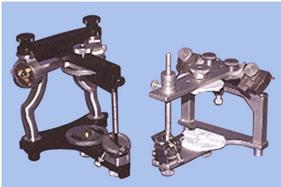
9.2.1. Purpose. An articulator is a mechanical device, which represents the temporomandibular joints and the jaw members, to which maxillary and mandibular casts are attached. It is used to set artificial teeth in prosthetic appliance fabrication. Two types of articulators, Whip-Mix and Hanau H2 158, are shown in Figure 9.1.
Figure 9.1. Whip-Mix and Hanau H2 158 Articulators.
9.2.2. Maintenance.
9.2.2.1. At the first sign of improper operation, clean the articulator with wax solvent, dry it with a blast of air, apply a light film of machine grade oil or graphite, and wipe off the excess oil or graphite to prevent an accumulation of dust and debris.
9.2.2.2. When the articulator is not in use, store it in a clean, dry atmosphere away from dust and acid fumes. Never use a hammer or pliers to make adjustments.
9.2.2.3. Gasoline and naptha are flammable and leave an oxide film which attacks the metal. Alkalies present in scouring powders form a residue which restricts movement of the members. Never use the sand blaster, shell blaster, or sandpaper to remove plaster or stone from the instrument. Mounting rings and the articulator under them are particularly susceptible to corrosion. Coat the rings and the areas of the articulator they contact with a very thin film of vaseline.
¶ 9.3. Autoduplicator
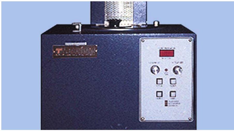
9.3.1. Purpose. The autoduplicator (Figure 9.2) conditions laboratory hydrocolloid by chopping it into small pieces and liquefying it by a high heat breakdown. After breakdown, the unit automatically cools the prepared colloid to a holding (storage) temperature of 125 to 127 °F.
Figure 9.2. Ticonium® Autoduplicator.
9.3.2. Maintenance.
9.3.2.1. Check the temperature daily. Do not leave the thermometer in the unit because the blades may strike the thermometer and cause damage to the duplicator.
9.3.2.2. Drain and clean the unit monthly. Unplug the duplicator and lift off the top; the motor and blades come off with the lid. Place this top section so the blades are not damaged. Wipe the blade assembly and inside of the tank with a sponge or cloth. Remove any debris and thoroughly clean the bottom of the tank and then reassemble the unit.
9.3.2.3. Remove the valve assembly weekly for cleaning and lubricating. Use the rubber tipped rod provided with the unit as a plug. Remove the stop screw on the back of the valve and pull out the handle. Clean it thoroughly, lubricate it lightly with silicone grease, reinsert it into the valve body, and replace the stop screw.
9.3.3. Safety Considerations. Handle the duplicator properly. Keep your hands out of the tank when the machine is operating because the blades are sharp and will damage your hands.
¶ 9.4. Hygroscopic Water Bath
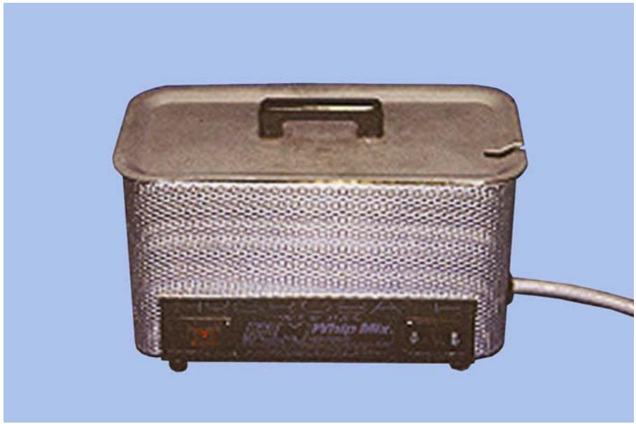
9.4.1. Purpose. The water bath (Figure 9.3) is used in conjunction with the hygroscopic investing technique for crown and fabrication. If properly calibrated, the bath raises room temperature water to 100 °F and maintains the water at that temperature. Immersion of an invested mold in this bath allows uniform expansion of the invested wax pattern and ensures a 100-percent humid atmosphere necessary for the hygroscopic component of investment expansion.
Figure 9.3. Hygroscopic Water Bath.
9.4.2. Maintenance. Periodically, check the temperature setting with a thermometer to ensure the unit maintains a temperature of 100 °F. Clean the holding tank and exterior of the unit weekly to prevent an accumulation of investment material residue.
9.4.3. Safety Considerations. Check the power line and plug daily for defects.
¶ 9.5. Shell or Sand Blaster
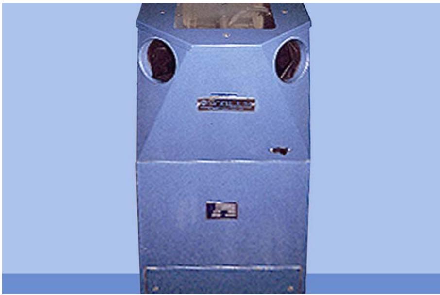
9.5.1. Purpose. The shell blaster and sand blaster have identical construction characteristics (Figure 9.4). They differ only in abrasive content and use as follows:
9.5.1.1. The shell blaster uses crushed walnut shells as an abrasive. It is used to remove gypsum products from an acrylic resin prosthesis during the deflasking operation. Walnut shells do not affect the teeth or denture base.
9.5.1.2. The sand blaster uses zircon grit as an abrasive. It is used in cast RPD work to remove casting investment and surface oxides from the metal framework. Never use the sand blaster on acrylic or porcelain.
9.5.2. Maintenance. Preventive maintenance is the same for both units. Shake the dust bag daily if applicable. Clean the bottom of the unit weekly, removing chunks of gypsum and other debris. Replace shells or sand as required. Replace a worn nozzle as needed, using operating manual instructions for guidance. Replace gloves if they are torn or holes appear. Change the viewing glass when it becomes pitted. Drain the air line periodically to eliminate condensed moisture.
9.5.3. Safety Considerations. Wear safety glasses or goggles. Do not operate the unit with the door or drawer open because this unit operates on 90 to 100 pounds per square inch of air pressure. Be sure protective gloves are in good repair. Check air and electrical connections for cuts, wear, or other damage.
Figure 9.4. Shell or Sand Blaster.
¶ 9.6. Bunsen Burner
9.6.1. Purpose. This burner (Figure 9.5) is used in the laboratory for heating wax-carrying instruments and a variety of other procedures where an open flame heat source is required.
Figure 9.5. Hanau Touch-O-Matic® Burner.
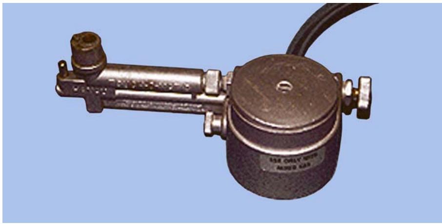
9.6.2. Maintenance. The burner has few moving parts and requires little maintenance. When wax or similar materials drop into the burner, remove the burner assembly from the unit and clean it in boiling water. After boiling and before reattaching the burner assembly, blow out any excess water from pilot tube, gas inlet tube, and flame orifice. Be sure the small round O-ring attached to the projecting brass tubing of the burner is replaced before reassembly.
9.6.3. Safety Considerations. Use an approved, noncollapsible hose for connecting the burner to a gas outlet. Inspect the unit and hose for loose connections and defects. Never place your head or arms over the flame when you reach for other objects. Turn the burner off when not in use.
¶ 9.7. Casting Machine (General)
9.7.1. Purpose. Casting machines are devices that fling molten metal into a mold. The Unitek Autocast is an electronic induction type casting machine used to cast all kinds of dental alloys (Figure 9.6). In the Air Force, the casting machine is used primarily to cast metal-ceramic substructures, but it can also be used to cast full gold units or RPD frameworks. Induction casting machines use an electromagnetic field which is set up around the metal. It melts the metal by electrical resistance.
Figure 9.6. Casting Machine (Unitek® Autocast).
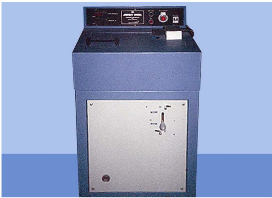
9.7.2. Maintenance. Clean the casting well of any debris after each use. No other lubrication or maintenance is required.
9.7.3. Safety Considerations. Keep your hands clear of the casting arm and always balance the casting arm before burnout of the mold. Wear safety glasses or goggles. Do not operate this machine when water leaks are evident or water is present near the machine—this is a high voltage and amperage unit. Keep debris out of the well, especially under the coil assembly.
¶ 9.8. Broken-Arm Casting Machine With Safety Lid
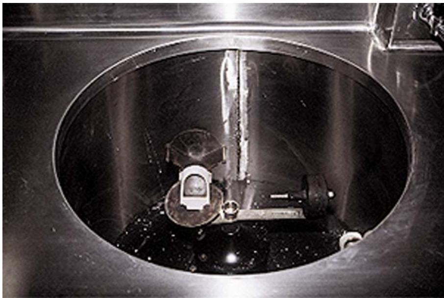
9.8.1. Purpose. This type of casting machine (Figures 9.7 and 9.8) is used to melt conventional and porcelain fused-to-metal gold alloys and cast them by centrifugal force into a heated mold. The machine requires an external heat source to melt the metal, usually a gas and air blowpipe. The casting machine is spring loaded and wound to operate.
9.8.2. Maintenance. Make sure the arm is balanced to prevent vibration damage and certain miscast. Lubricate the machine with three drops of oil at the base of the rotating shaft after 200 castings. When winding the machine, do not exceed four turns because too many turns will weaken or break the spring. Keep the casting well cleaned and dusted.
9.8.3. Safety Considerations. Always wear safety glasses and make sure the blowpipe is pointed in a safe direction. Keep your hands clear when you release the casting arm. Ensure the well of the casting machine is clean and uncluttered. Use proper tongs to handle the casting rings.
Figure 9.7. Broken-Arm Casting Machine With Safety Lid.
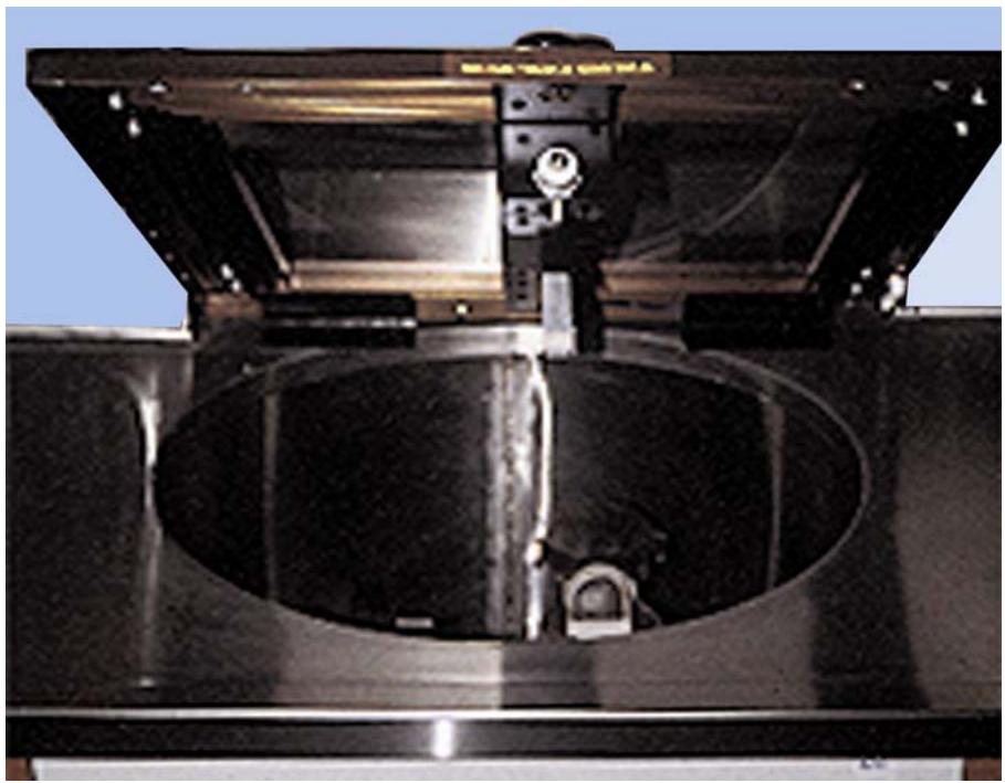
Figure 9.8. Broken-Arm Casting Machine.
¶ 9.9. Ticomatic® Electric Casting Machine
9.9.1. Purpose. The Ticomatic casting machine (Figure 9.9) is similar to, but larger than the Unitek® Autocast. The Ticomatic is primarily designed to cast RPD frameworks, but it can be modified for other applications.
Figure 9.9. Ticomatic® Casting Machine.
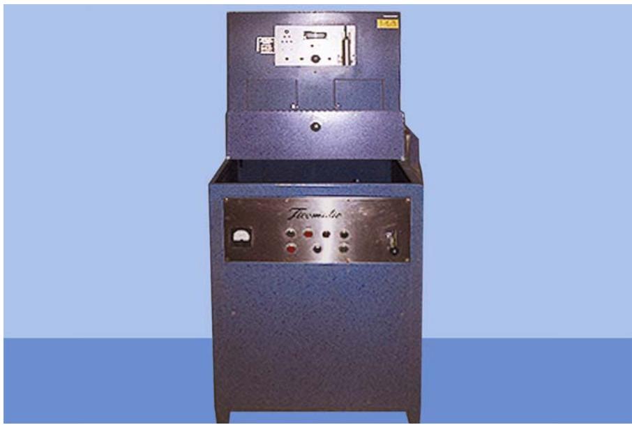
9.9.2. Maintenance. Keep the well of the casting machine clean. Remove all debris that might interfere with the coil drop and prevent the safety switch from working. Do not oil the coil assembly rods. Use a powdered lubricant (molybdenum disulfide is recommended) and wipe off any excess. Remove the crucible slide holder once a month and clean the tracks. Clean all sliding surfaces and lubricate them with the powdered lubricant. Do not neglect to lubricate the two contact fingers on the coil assembly. (These must be vertical and tight.) Be sure the crucible is in good condition.
9.9.3. Safety Considerations. Keep your hands clear of the casting arm (Figure 9.10). Wear safety glasses or goggles. DO NOT operate this machine when water leaks are evident or water is present near the machine. This is a high voltage and amperage unit. Keep debris out of the casting well, especially under the coil assembly. Be sure the arm is balanced. DO NOT, under any circumstances, raise the coil assembly while the arm is rotating.
¶ 9.10. Pneumatic Chisel
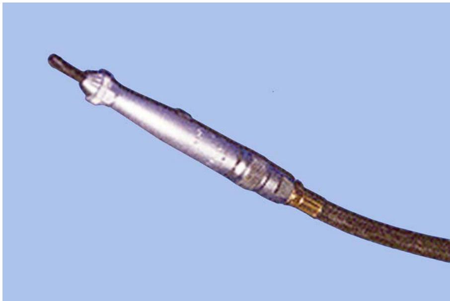
9.10.1. Purpose. The pneumatic (air) chisel (Figure 9.11) is primarily used to break or fracture artificial stone; for example, divesting processed dentures, removing stone from the tongue space of mandibular casts, or removing stone from the mounting rings.
9.10.2. Maintenance. Place six drops of lightweight oil in the air inlet daily. Check air pressure (90 pounds per square inch is necessary for efficient operation). Check the air periodically for moisture content and drain the air line as required.
9.10.3. Safety Considerations. Wear safety glasses when you deflask dentures. Keep the area clean and free of debris. Be sure attachments are securely attached into the nozzle.
¶ 9.11. Wells® Quick-Release Chuck
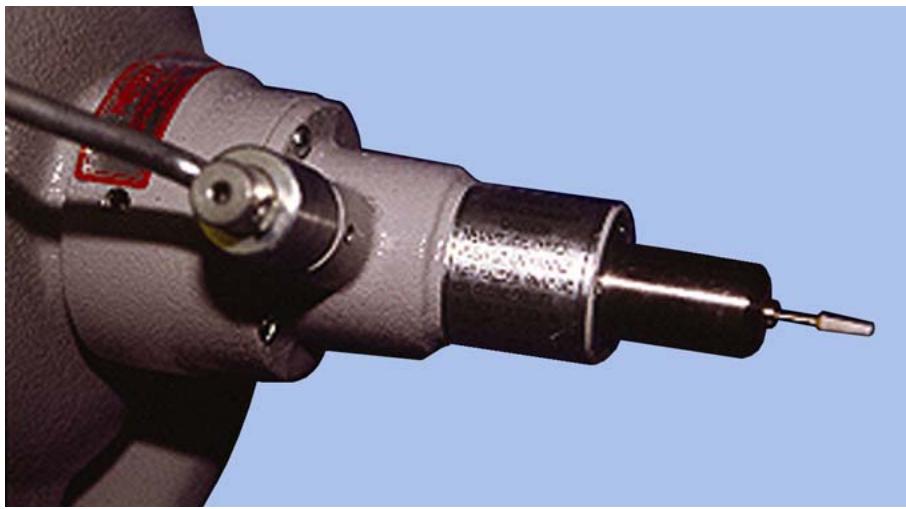
9.11.1. Purpose. When it is correctly installed on a bench lathe, the Wells® Quick-Release Chuck allows the operator to change chucks and burs while the lathe is in motion, which greatly decreases the time spent in the finishing and polishing procedures (Figure 9.12).
Figure 9.10. Ticomatic® Casting Arm.
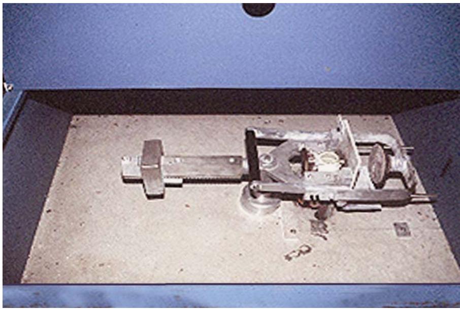
Figure 9.11. Pneumatic Chisel.
9.11.2. Maintenance. Do not attempt to operate the chuck unless it is properly installed on the lathe. Never use oil or solvents of any kind on it. Never close the collet without a tool (chuck or bur) in the collet. Allow the clutch spring to slowly engage the clutch. (Never push up on the handle or let the handle snap up.) Do not remove or attempt to defeat the purpose of the safety strap. Clean the collets once a week.
9.11.3. Safety Considerations. See paragraph 9.25.3 for safety precautions on the standard bench-mounted lathe.
Figure 9.12. Wells® Quick-Release Chuck.
¶ 9.12. Ultrasonic Cleaning Unit
9.12.1. Purpose. The ultrasonic cleaning unit is filled with locally or commercially prepared cleaning compounds (Figure 9.13). It uses ultrasonic vibrations to clean dental restorations, appliances, and small equipment items.
Figure 9.13. Ultrasonic Cleaning Unit.
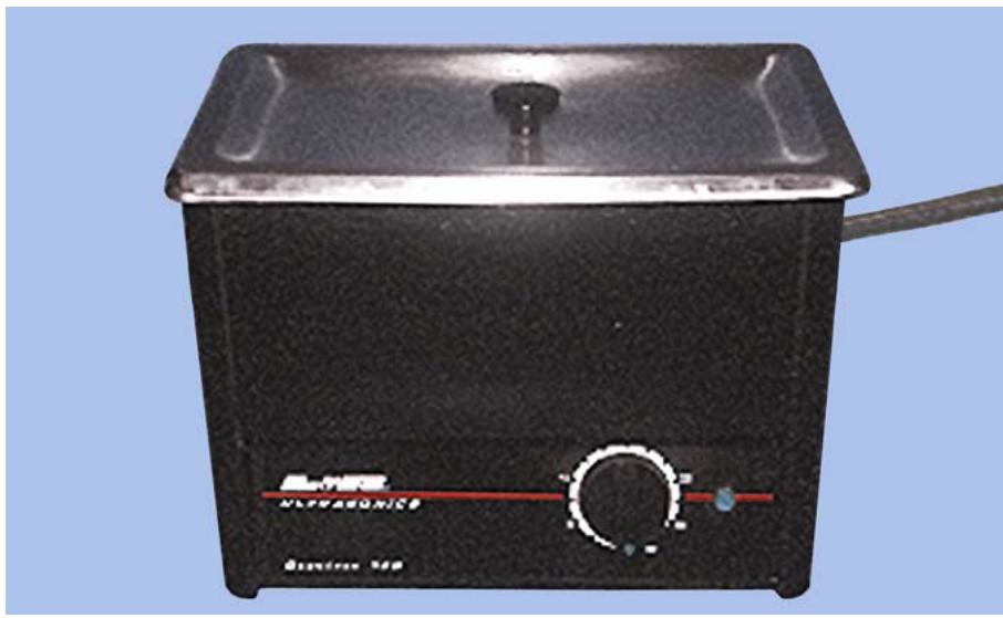
9.12.2. Maintenance. Never run the machine dry. Always ensure there is at least 1 inch of solution in the tank. There should be enough cleaning solution to completely cover the items being cleaned in the tank or beaker. Clean the holding tank and exterior surfaces of the unit periodically. Replace the drain cap before refilling the tank. Use aluminum foil to test the effective operation of an ultrasonic cleaning unit. Place a piece of foil, large enough to cover at least half the tank area, in the tank and set the timer for 5 minutes. (A properly functioning unit will have created multiple holes in the foil.)
9.12.3. Safety Considerations. Never put highly flammable liquids in the tank. Do not place your fingers in the cleaning solution while the unit is activated. Do not immerse unit into water to clean the tank. Check the power line and plug daily for defects. Keep the area around the unit clean and dry.
¶ 9.13. Hanau Model II® Curing Unit
9.13.1. Purpose. Curing or polymerization of acrylic resins is a chemical reaction between the polymer and monomer. Heat generated by this reaction may cause an internal temperature as high as 300 °F. When monomer boils, it results in a porous denture base. The objective in curing is to control the temperature generated by the polymerization so the monomer does not boil. A curing unit (Figure 9.14) must contain:
9.13.1.1. A positive means of controlling the rate of heating.
9.13.1.2. A rack to prevent flask and heating coil contact.
9.13.1.3. A volume of water that is sufficient to prevent too rapid a rise in temperature.
Figure 9.14. Hanau Model II® Curing Unit.
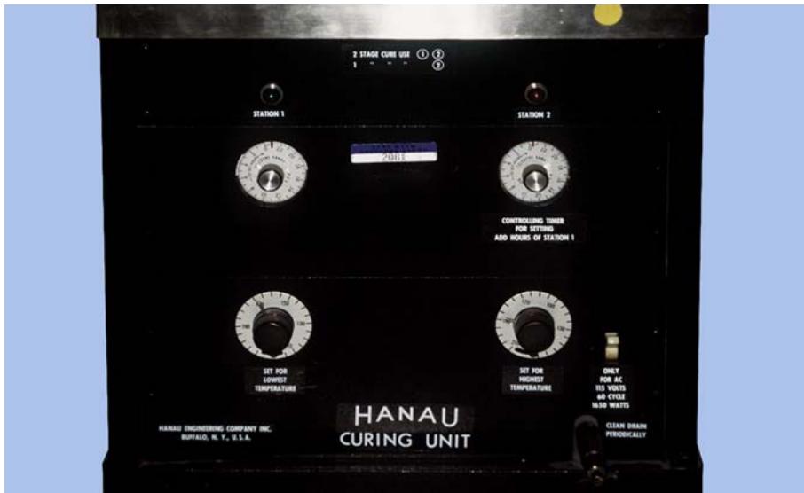
9.13.2. Maintenance. Check the electrical cord for wear or damage. Ensure the unit has a grounding plug. Check the unit for water leaks in the tank or valve. Drain and clean the tank periodically, removing debris with a stiff brush (not a steel one) and cleaning solvent. Remove lime deposits by soaking with acetic acid (vinegar). Perform the following operational check at least monthly:
9.13.2.1. Fill the tank half full of water. Set the Station 1 thermostat at 165 °F and the timer for 1 1/2 hours. Set the Station 2 thermostat at 212 °F and the timer for 2 1/2 hours. Cover the tank and turn the switch to “ON.” (The water should reach 165 °F in approximately 50 minutes.) Check the temperature with an accurate thermometer.
9.13.2.2. Make sure both clocks run simultaneously so the control of the heating coil is transferred to Station 2 as Station 1 expires. (The water temperature should reach 212 °F in about 25 minutes.) Again, check the temperature with an accurate thermometer.
9.13.2.3. If the machine malfunctions, do not attempt to repair or adjust it. Call your medical equipment repair technician to perform necessary adjustments.
9.13.3. Safety Considerations. Be careful when you remove cases from this curing unit. The water in the tank, as well as flask and carriers, remains hot for long periods of time. Before each use, check the power line and plug for defects.
¶ 9.14. Ivocap® Curing Unit
9.14.1. Purpose. The unit (Figure 9.15) provides a controlled environment during curing of dentures, using the Ivocap injection mold technique. It raises water temperature to 100 °C and maintains it during the curing process.
Figure 9.15. Ivocap® Curing Unit.
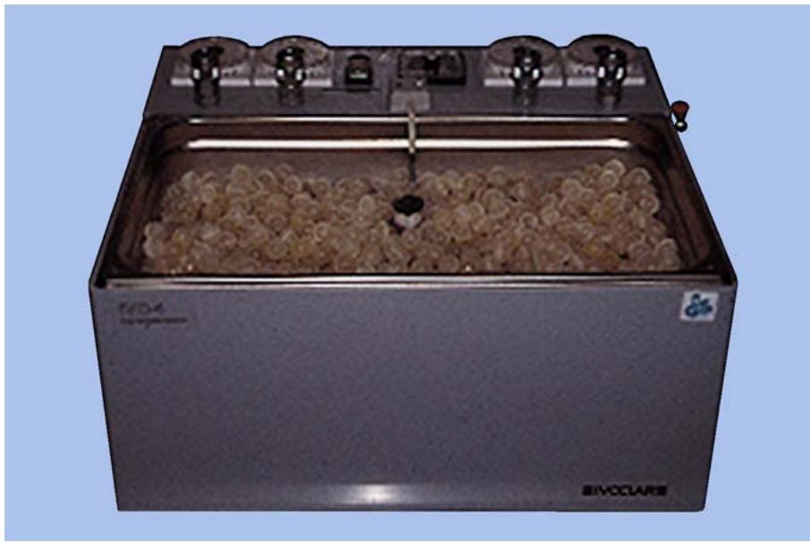
9.14.2. Maintenance. Periodically check the power cord for damage. At least monthly, perform an operational check to ensure water temperature is maintained at 100 °C. Always ensure there is an adequate number of insulation floaters to cover the water’s surface. As sediment builds up, clean the tank with a brush and mild solvent
9.14.3. Safety. Be careful when removing the flask from the boiling water following the curing process. Ensure the area around the curing unit is kept clean and dry.
¶ 9.15. Pindex® Dowel Pin Drill
9.15.1. Purpose. The dowel pin drill (Figure 9.16) is used to drill parallel dowel pin holes in the underside of an initial pour of a working cast. Specially designed dowel pins are then cemented in the holes and the cast base is completed. The dowel pin drill has a light beam or mechanical pointer used to position the drill bit directly under the tooth preparations.
9.15.2. Maintenance. Frequently vacuum or brush away accumulated dust and debris. Do not use air pressure to clean the machine because the pressure may force dust into the moving parts. Replace the drill bit when it is no longer sharp. Excessive pressure must be used during drilling if the drill bit is allowed to become dull.
9.15.3. Safety Considerations. Do not lower the work table suddenly or too quickly. Instead, use a slow gradual motion and always allow the drill to do the cutting. Wear safety glasses when operating the machine or cleaning the dowel pin holes of debris with compressed air.
Figure 9.16. Pindex® Dowel Pin Drill.
¶ 9.16. Ticonium® Electro Polisher
9.16.1. Purpose. The Ti-Lectro ® polisher (Figure 9.17) polishes cast RPD metal frameworks, using an electrolytic depleting process.
9.16.2. Maintenance. The corrosive characteristics of acid require special maintenance precautions. After polishing, rinse the electrode clip in neutralizing solution to prevent the corrosive effects of the Ti-Lectro ® solution on the electrode clip. Wash off any acid on the controller unit. Drain the solution and clean the sediment out of the bowl twice a week. Replace worn clips as required. Clean the rinse bowl daily. Clean corroded electrical contacts as necessary.
9.16.3. Safety Considerations. To avoid injury while using the Ti-Lectro® polisher, careful steps must be taken. Always use rubber gloves, an apron, and a protective face shield when operating the machine. Keep the acid solution covered when the polisher is not in use. Use the polisher in a well ventilated area. If any of the solution gets on hands or clothing, wash it off immediately.
¶ 9.17. Denture Flask
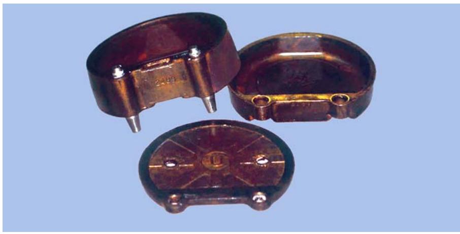
9.17.1. Purpose. A denture flask (Figures 9.18 and 9.19) is used to form the mold that processes the acrylic resin portion of the prosthesis. The flask is comprised of four sections or parts, the knockout plate, bottom half (drag), top half (cope), and cap (lid). Each flask has the same number on all of its parts, except the knockout plate. It is imperative to keep the parts with the same numbers together because they are machined to fit each other.
Figure 9.17. Ticonium® Electro Polisher.
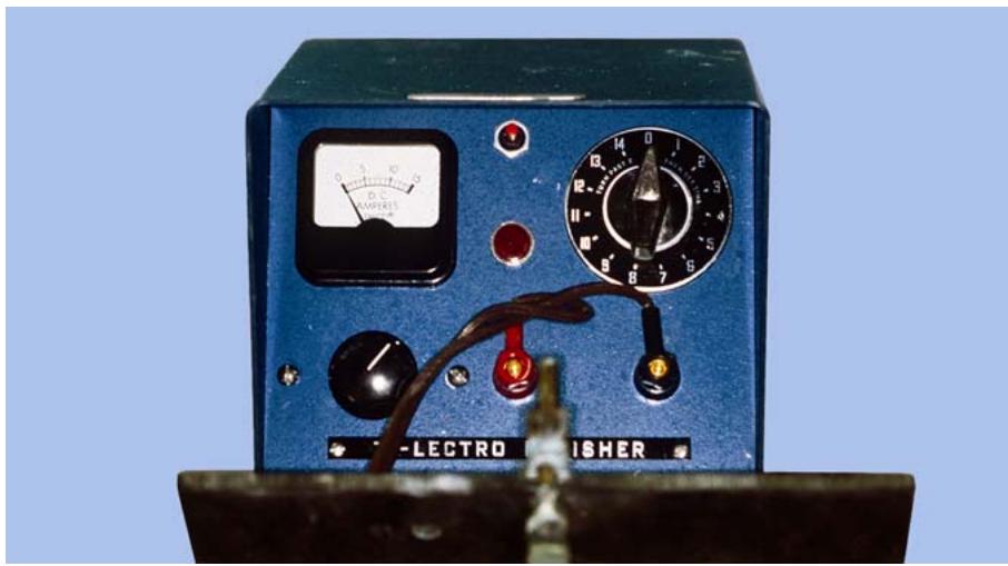
Figure 9.18. Denture Flask (Closed).
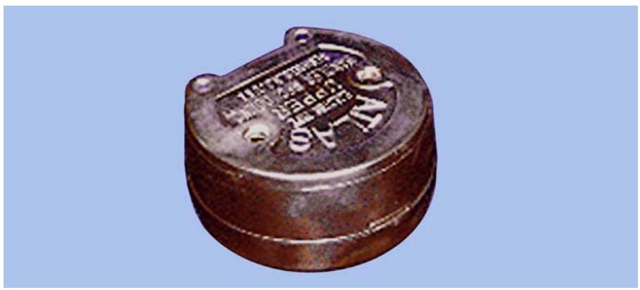
Figure 9.19. Denture Flask (Exposed View).
9.17.2. Maintenance. Clean and apply a light coat of petrolatum to the flask after each use. Always use the ejector press, not a metal hammer, to remove the molds. When the brass on the flask tarnishes, restore its appearance with fine steel wool or a fine emery cloth.
¶ 9.18. Electric Handpiece
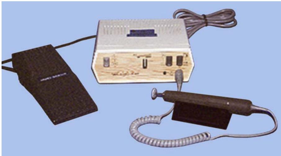
9.18.1. Purpose. The electric handpiece (Figure 9.20) is a handheld electric motor with a revolving spindle and a chuck in the front to hold burs, stones, and mounted points. It provides ease of changing burs and a great degree of maneuverability while contouring prostheses.
Figure 9.20. Electric Handpiece.
9.18.2. Maintenance. To care for the handpiece, always check the manufacturer’s instructions. Handpieces contain permanently sealed and lubricated bearings that do not require lubrication. Brush the motor housing daily to remove dust, using accessory brush provided. Clean the handpiece chuck and motor at least weekly to remove dust and debris. Never start the handpiece while the chuck is in the release position because this could damage the unit.
9.18.3. Safety Considerations. Do not wear loose fitting clothing or jewelry because they could become caught in moving burs. Watch for spinning stones and burs and keep them away from your fingers. Do not use attachments that vibrate or do not run true. Always wear safety glasses.
¶ 9.19. Beeswax Heater
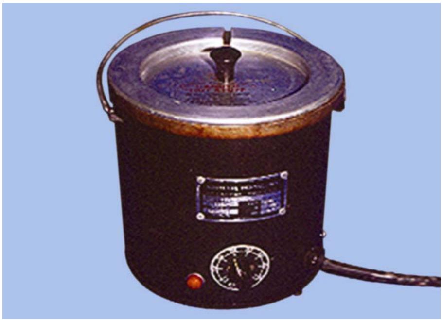
9.19.1. Purpose. The beeswax (Figure 9.21) heater is designed to melt refined beeswax and maintain the wax at a holding temperature between 270 and 300 °F. It is used primarily for wax dipping refractory casts in RPD fabrication.
9.19.2. Maintenance. Prevent the beeswax from burning by periodically checking the holding temperature with a thermometer. Clean the debris from the holding tank and exterior of the unit each time the wax is changed.
9.19.3. Safety Considerations. Before each use, inspect the power line and plug for defects. Use a potato masher or similar carrier to immerse the casts into the molten wax. Do not drop the casts into the molten wax because the splashing of hot wax can result in serious burns. Avoid touching the exterior of the unit during and immediately after its operation. Wear safety glasses or goggles to prevent eye injury. Always keep the wax pot away from the edge of the bench to reduce chances of tipping it over.
Figure 9.21. Beeswax Heater.
¶ 9.20. Dura Dip® Electronic Wax Heater
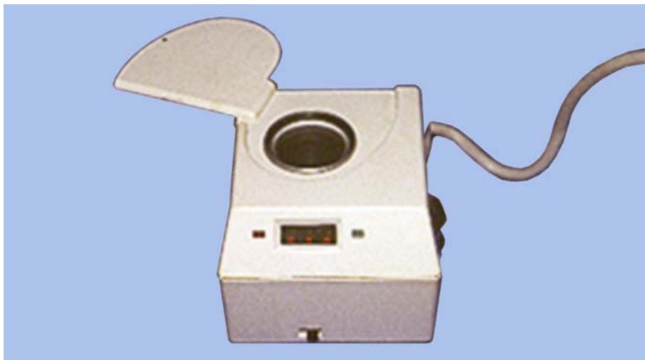
9.20.1. Purpose. The Dura Dip ® electronic wax heater (Figure 9.22) is used to melt specially prepared inlay wax for the wax-dipping technique used to form coping patterns. The unit’s electronic circuitry and sensor allow precision adjustment of the molten wax’s temperature.
Figure 9.22. Dura Dip® Electronic Wax Heater.
9.20.2. Maintenance. Never pry unmelted wax from the well because severe damage to the silicone diode temperature sensor may result. Keep the wax well covered when not in use. Periodically remove the cover and clean any excess wax that may have collected.
9.20.3. Safety Considerations. Check the power line and plug before each use. Avoid contact with the hot molten wax.
¶ 9.21. Electric Wax Heater (General)
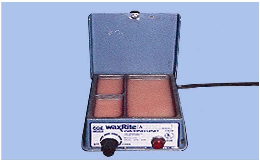
9.21.1. Purpose. The electric wax heater (Figure 9.23) is used to melt a variety of dental waxes. It maintains the waxes at a workable temperature without overheating them.
Figure 9.23. Electric Wax Heater.
9.21.2. Maintenance. Clean the unit periodically to prevent accumulation of debris in the bottom of the wax compartments.
9.21.3. Safety Considerations. Check the power line and plug for defects. Handle the unit carefully when it is activated. Unplug it when not in use.
¶ 9.22. High Speed Turbine Handpiece
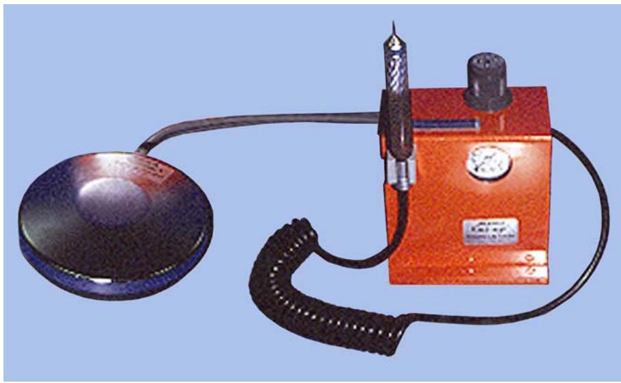
9.22.1. Purpose. This air driven handpiece (Figure 9.24) with bur rotation from 0 to 300,000 rpm uses friction grip burs and enables you to accomplish fine detailed contouring of porcelain occlusals.
Figure 9.24. High Speed Turbine Handpiece.
9.22.2. Maintenance. Never run handpiece without a bur in the chuck. Lubricate the headpiece after 3 to 5 hours of operation or at the end of each workday. (See the manufacturer’s manual for guidance.) Always ensure burs are true before using them. Ensure the air pressure is set at the manufacturer’s recommendation; higher air pressure could damage the handpiece.
9.22.3. Safety Considerations. Always fully seat burs before operation. Safety glasses must be worn while operating handpiece.
¶ 9.23. Whip-Mix® Vacuum Investor
9.23.1. Purpose. The vacuum investor (Figure 9.25) is used to spatulate and evacuate air from a mix of gypsum material. It is used primarily for mixing hydrocal to pour impressions and vacuum spatulating investments used in the fabrication of crowns and FPDs. It is also used to mix alginate impression material.
Figure 9.25. Whip-Mix® Vacuum Investor.
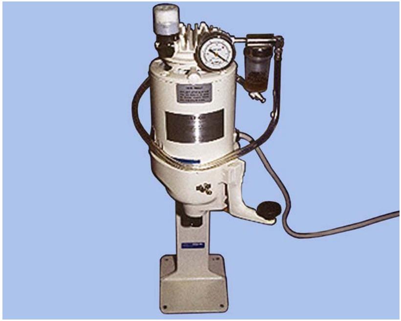
9.23.2. Maintenance. Insert the blades into the mixing bowl before positioning the shaft in the chuck. Maintain the correct level in the oil jar. Continue to run the unit for 1 minute after use to oil the vacuum chamber and remove the moisture from the pump. Clean the bowl and attachments as soon as possible after use. Occasionally check all O-rings and fittings to ensure proper vacuum is maintained. LUBRIPLATE, which is supplied with the machine, should be applied several times a year to the shaft and O-rings. Replace the gauze in the debris trap as required.
9.23.3. Safety Considerations. Use precautions against electrical shock. Keep your fingers away from the rotating parts.
¶ 9.24. Reline Jig
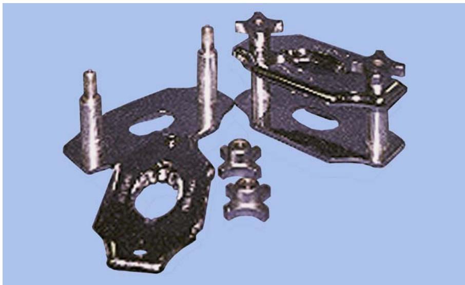
9.24.1. Purpose. When used correctly, the sectional jig (Figure 9.26) is a fast, accurate way to reline dentures. This technique eliminates the need for flasking and mounting in an articulator, yet produces excellent results.
9.24.2. Maintenance. General cleaning is all this equipment requires.
Figure 9.26. Jectron® Reline Jig.
¶ 9.25. Bench-Mounted Lathe
9.25.1. Purpose. This lathe (Figure 9.27) with the Wells Quick-Release Chuck combination is used for a variety of grinding, finishing, and polishing procedures in the dental laboratory.
Figure 9.27. Bench-Mounted Lathe.
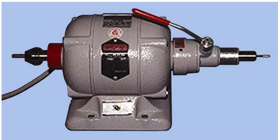
9.25.2. Maintenance. The bearings are factory sealed and require no lubrication. Do not flip the switch from “HIGH” to “LOW ” to slow the machine down. The chuck must be periodically cleaned and lubricated to prevent rusting and ensure its smooth function.
9.25.3. Safety Considerations. Check the cord and plug for wear or damage. Wear protective safety glasses during finishing and polishing procedures. Do not leave a running lathe unattended. Turn it off when not in use. Check all chucks and attachments to ensure they are securely mounted before you start the lathe. Do not use attachments that vibrate or do not run true. Do not make adjustments or replace chucks, wheels, or similar attachments while the lathe is running, unless the machine is equipped with an automatic chuck. Do not attempt to stop a running lathe by grasping the attachment with your hands.
¶ 9.26. Lathe Polishing Unit
9.26.1. Purpose. This unit is equipped with a suction device to draw smoothing and polishing agents away from the operator (Figure 9.28 and 9.29). It is used to low-speed polish cast RPD frameworks and gold FPDs. It is also used for all types of acrylic resin restorations.
Figure 9.28. Kavo® Polishing Unit.
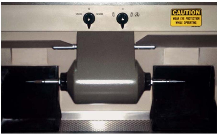
Figure 9.29. Floor-Mounted Lathe.
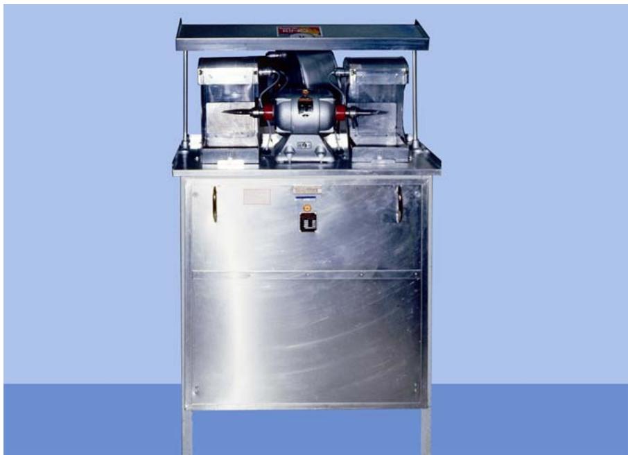
9.26.2. Maintenance. Dust and clean the motor housing and unit daily. Replace the filters as required.
9.26.3. Safety Considerations. Wear safety glasses. Check electrical connections for wear or damage. Use light pressure. Do not talk to anyone while using this machine. Release the prosthesis if it hangs in the polishing wheel. Do not try to hurry any polishing procedure.
¶ 9.27. High-Speed, Metal-Finishing Lathe
9.27.1. Purpose. The extremely hard chrome alloy used in removable partial denture construction requires a high-speed lathe for finishing and polishing (Figure 9.30). NOTE: This lathe is not recommended for finishing gold.
Figure 9.30. High-Speed, Metal-Finishing Lathe.
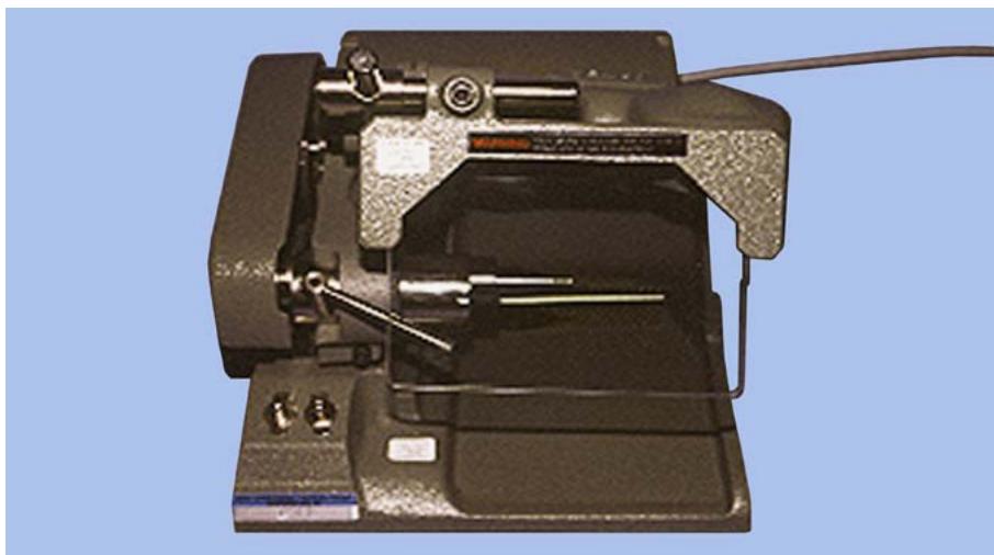
9.27.2. Maintenance. Oil the motor every 6 months with three drops of light machine oil in each oil cup. Maintain correct belt tension. (If the belt is too loose, the spindle will not turn.) Adjust the tension by loosening the screws under the spindle housing and turning the spindle clockwise. Use proper light bulbs in the unit’s light receptacle. Clean and oil the collet after each day’s use. Never close the collet without a mandrel in place because the clutch is plastic and will freeze up if the collet is allowed to lock. Follow the manufacturer’s directions for inserting, removing, or releasing the attachments. Always hold a truing stone to mounted wheels and mounted rubber points while they are turning on the lathe and before using them on practical work.
9.27.3. Safety Considerations. Always wear safety glasses. Pay strict attention to your work. Keep the belt guard in place while the lathe is running. Be sure the collet releases the bur shank. Keep fingers out of the belt guard and away from the stones and burs. Keep the glass shield in place and make sure it is not cracked or broken. Use the vacuum apparatus to draw off grinding dust. Check the power line and plug for defects before each use.
¶ 9.28. Comco® Microblaster and Work Station
9.28.1. Purpose. The microblaster (Figure 9.31) has many air abrasive uses. It can be used to remove investment and oxide residue from castings, prepare metal substructure surfaces before and after the oxidation step, prepare porcelain surfaces prior to subsequent firings, cut detailed anatomy into porcelain occlusals, and polish metal surfaces. The unit can use 25- to 50-micron sized aluminum oxide abrasive or 50-micron glass beads (for polishing). Regulate the air pressure to change the cutting power of the abrasive. Comco also makes an optional dust collection system the microblaster and work station can use as a base.
9.28.2. Maintenance.
9.28.2.1. Do not depressurize the microblaster after each use. It is designed to be pressurized in the morning and not depressurized until the end of the day.
Figure 9.31. Comco® Microblaster and Work Station.
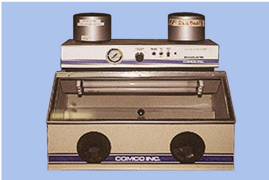
9.28.2.2. When the tank cover is removed to change the powder, brush the excess powder off the top of the tank and out of the threads. A small stiff brush is ideal for this purpose. At weekly intervals, spray or wipe a dry lubricant such as graphite, molycote, or teflon powder on the tank threads. If an aerosol dispenser is used, the lubricant is suspended in a solvent. Allow a few minutes for the solvent to evaporate before closing. When using an aerosol, always shield the inside of tank from the spraying operation. Routinely inspect the threads on the tank and cover for excessive wear.
9.28.2.3. Each day, slide the hose back through the pinch valve tube about 1/2 inch. When 6 to 9 inches have been pushed back, reverse the procedure. This will greatly increase the life of the hose.
9.28.2.4. Each week, with the machine turned off and depressurized, examine the handpiece abrasive hose for soft spots. Examine the hose in the area of the pinch valve and along the first 2 or 3 inches next to the fitting at the rear panel. The hose should be evenly firm along its length without any soft spots. Whenever a soft spot is detected, cut back the hose to that point and reattach it to the fitting.
9.28.2.5. Each month, pull the power cord plug and remove the cabinet cover. Inspect the unit for obvious leaks. Clean thoroughly with small brush and vacuum hose. (Never use air or try to blow abrasives unless you are working in a large efficient hood.) Replace the power cord, energize the machine, and blow out the lines for a few seconds. Cover the microblaster and return the unit to service.
9.28.2.6. If the machine malfunctions or is in need of a replacement part, do not attempt to repair or adjust it. Instead, call the medical equipment repair person to have a qualified technician service the unit.
9.28.3. Safety Considerations. Keep the work station lid closed when the microblaster is in use. Do not direct the air blast in a direction that would cause the abrasive to enter underneath fingernails or into an exposed cut. Check the power cord and plug before use.
¶ 9.29. ESPE Rocatector® Microblaster
9.29.1. Purpose. The Rocatector microblaster (Figure 9.32) is a part of the ESPE Visogem ® system that creates a gap free bond between the metal substructure and the veneer material. First, sand blast (Rocatec-Pre) each metal substructure blast to clean the surface. Next, blast the metal substructure with a material (Rocatec-Plus) that creates an adhesive coating onto the metal in preparation for the veneer application.
Figure 9.32. ESPE Rocatector® Microblaster.
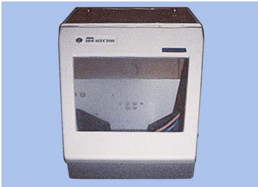
9.29.2. Maintenance. It is very important to fill the blasting material into the correct storage chamber. Filling the blasting material into the wrong storage chamber will cause the bond between metal and veneer material to be lost. Store blasting materials in a clean dry area. Periodically check to ensure the level in storage containers is above minimum level. If the material drops below minimal level, a sufficient layer of adhesive coating may not be applied to the metal substructure during the application process. Air pressure should be at least 2.5 bars for proper operation.
9.29.3. Safety Considerations. Keep the lid on the Rocatector closed when in use. Do not direct the air blast in a direction that would cause the abrasive to enter underneath fingernails or into an exposed cut. Check the power cord and plug before use.
¶ 9.30. Microscope
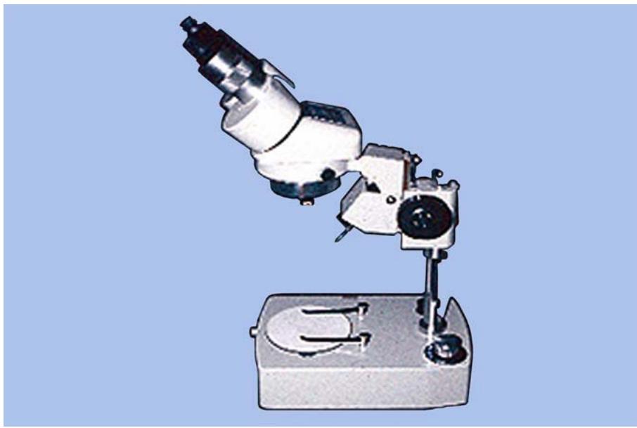
9.30.1. Purpose. A microscope is mainly used in the laboratory to trim dies, facilitate waxing margins on crowns, and seat castings (Figure 9.33). A microscope can also be used anytime magnification is needed.
9.30.2. Maintenance. The eyepiece and lenses should never be wiped while dry. Dust can be removed with a camel’s hair brush or air. Lens paper, folded and moistened with an approved lens cleaner such as xylol or xylene, should be used to clean glass surface. Periodic service may be needed and should only be done by a qualified authorized technician.
Figure 9.33. Stereo Microscope.
¶ 9.31. Dehydrating Oven
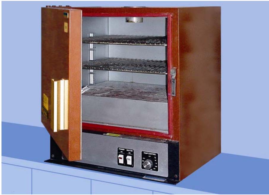
9.31.1. Purpose. A dehydrating oven (Figure 9.34) is used to dry refractory casts prior to sealing them with beeswax.
Figure 9.34. Dehydrating Oven.
9.31.2. Maintenance. The inside of the furnace should be cleaned and vacuumed at least weekly.
9.31.3. Safety Considerations. Take precautions for handling hot materials. Never place a sealed container in the oven. Periodically check the power line and plug for defects.
¶ 9.32. Fixed Prosthetic Burnout Oven
9.32.1. Purpose. The burnout oven (Figure 9.35) is used for wax elimination, preheating, and heat treatment. The paramount requirements of a burnout oven are:
9.32.1.1. An accurate pyrometer.
9.32.1.2. A method of controlling the rate of temperature rise.
9.32.1.3. A positive means of maintaining a constant temperature.
Figure 9.35. Fixed Prosthetic Burnout Oven (Jelenko Accu-Therm II 750®).

9.32.2. Maintenance. Clean the muffle of the burnout oven to remove all debris. Vacuum inside the muffle as required. Check the pyrometer of the oven every 3 months. Use temperature pills or a pure metal to check for proper calibration. Never operate the burnout oven at higher temperatures than those recommended by the manufacturer. Keep the muffle door closed when the furnace is cooling because an open door leads to too rapid cooling which may crack the muffle.
9.32.3. Safety Considerations. Check the electrical connections for fraying. Locate the oven within easy reach of the casting well. Keep the area clean and uncluttered. Use tongs to handle hot rings.
¶ 9.33. Porcelain Oven
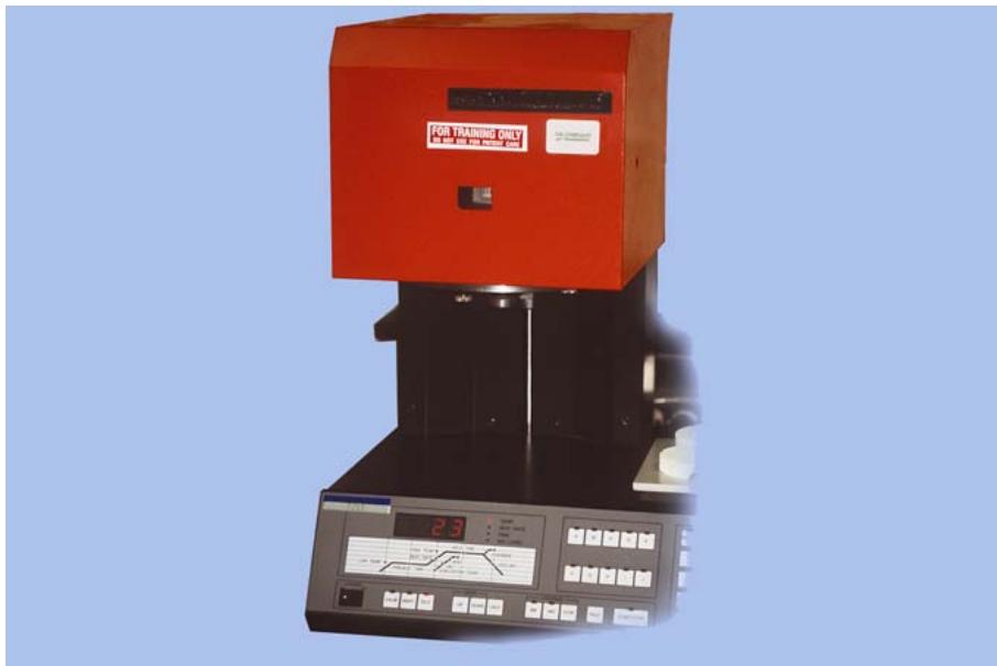
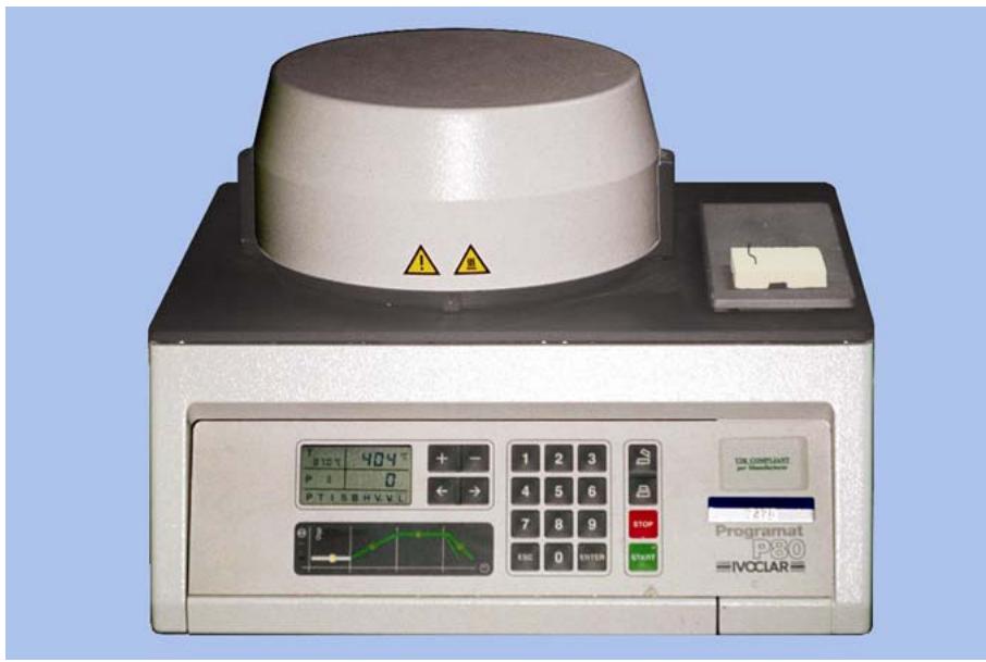
9.33.1. Purpose. A porcelain oven (Figures 9.36, 9.37, and 9.38) is a specialized unit designed for firing porcelain in the fabrication of crowns and FPDs.
9.33.2. Maintenance.
9.33.2.1. Clean and dust the outside of the unit daily. Do not wipe the pyrometer with a rag because wiping may magnetize the needle. Dust the glass with a soft brush. Keep the muffle clean and free of debris and flakes of porcelain. Cool the furnace with the door closed because rapid cooling may crack the muffle. Use pure metals with known melting points or temperature pills to calibrate the muffle.
Figure 9.36. Dentsply® Multimat 99 Porcelain Oven With Movable Muffle.

Figure 9.37. Jelenko® Commodore 100 With Stationary Muffle.
9.33.2.2. Place the metal strip on the sagger tray and insert the tray into the furnace.
9.33.2.3. Set the temperature control at the melting point of the metal used. Adjust the current to achieve a rise of 100 °F per minute.
9.33.2.4. Observe the metal until it melts. Check the pyrometer. If the temperature is lower than the control was set for or if the metal has not melted, calibrate the furnace. Refer to the operating instructions to locate the adjustment screw. Using a small screwdriver, turn the screw until the pyrometer agrees with the temperature control.
9.33.2.5. Cool the furnace and then repeat the procedure to check the calibration.
Figure 9.38. Ivoclar® Programat P-80 With Hinge Muffle.
9.33.3. Safety Considerations. The porcelain furnace operates at high temperatures. Use safety equipment and be careful handling hot items.
¶ 9.34. Ticonium® Super Oven
9.34.1. Purpose. The Ticonium® super oven (Figure 9.39) burns out up to 20 cases (molds) at one time. It has a spring-loaded door that opens upward. It is used primarily for burning out RPD framework molds.
Figure 9.39. Ticonium® Super Oven.
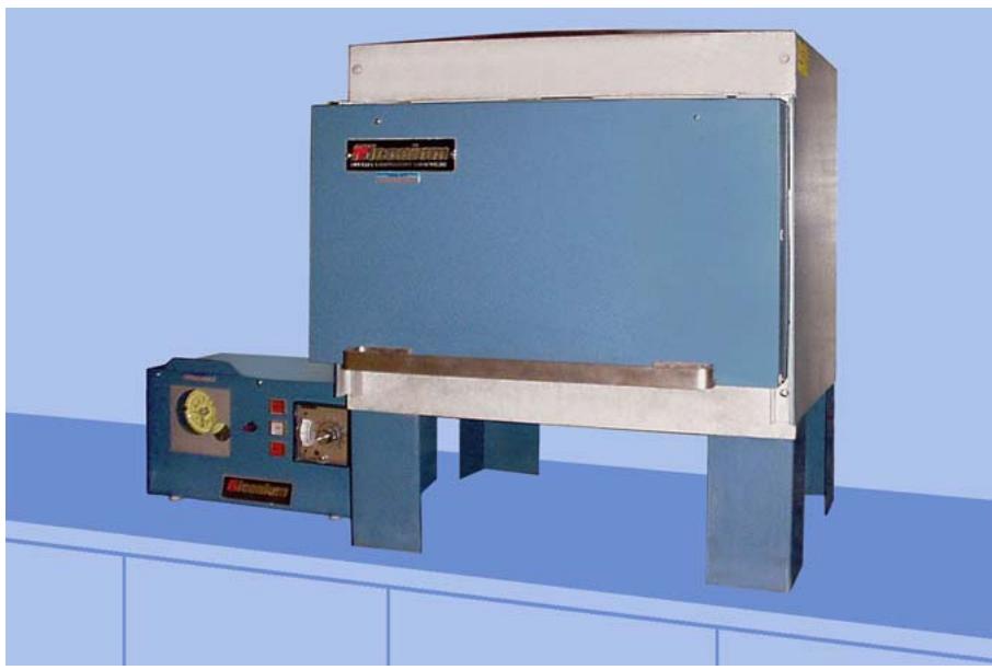
9.34.2. Maintenance. Maintenance is the same as for standard ovens, except for the springs on the door, which must be replaced as they weaken. There are also vent holes placed in the upper left and right back of the oven that need to be cleaned periodically to ensure a clean burnout. The super oven must be calibrated every 90 days. The procedures below should be followed closely for correct operation:
9.34.2.1. With the oven at room temperature, turn the unit on. Immediately check the temperature reading to make sure it corresponds to the room temperature. If a discrepancy exists, adjust the indicator. (Any difference in temperature found here will also be present at higher temperatures.)
9.34.2.2. After observing the pyrometer, run the temperature up to 1300 °F. Check for accuracy with temperature pills. Do not attempt further adjustment or repair of this unit.
9.34.3. Safety Considerations. Wear safety glasses and use heat reflecting gloves. Use proper tongs when handling hot molds. Mark hot molds with warning signs. Use an asbestos slab to hold hot molds after casting. Keep the inside of the oven and adjacent areas clean and uncluttered. Be sure the oven is in easy reach of the casting machine.
¶ 9.35. Pressure Pot
9.35.1. Purpose. The pressure pot (Figure 9.40) is a device used for curing relines and repairing complete dentures and denture base areas of RPDs when the procedure is accomplished with autopolymerizing acrylic resin. Curing the resin under pressure significantly reduces the possibility of porosity.
Figure 9.40. Pressure Pot.
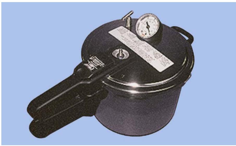
9.35.2. Maintenance. Periodically check seals, air inlets, and outlets for malfunctions. Activate the pressure relief valve to ensure it is operational. Periodically lubricate the gasket to prevent from drying out.
9.35.3. Safety Considerations. Never exceed the maximum air pressure indicated in the manufacturer’s instructions because excessive pressure may cause the pot to explode. Never apply heat to the pot when pressurized. Always exhaust all air before opening the pot.
¶ 9.36. Carrier Flask Press
9.36.1. Purpose. After dentures are packed with a press, the flasks are transfer to a carrier press (Figure 9.41) to be placed in the curing unit. The carrier press has two strong stainless steel springs that hold flasks under about 400 pounds of evenly distributed pressure.
Figure 9.41. Carrier Flask Press.
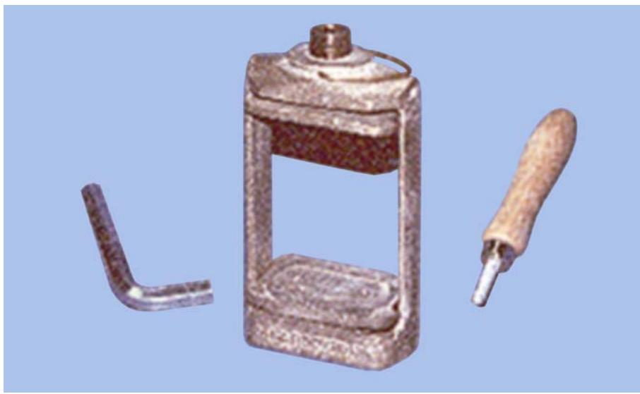
9.36.2. Maintenance. In addition to general cleanliness, inspect the stainless steel springs periodically for possible replacement.
9.36.3. Safety Considerations. The bulk of the metal (compress and flasks) retains heat after curing. Because it can cause serious burns, handle this heavy unit carefully before and after the processing procedure.
¶ 9.37. Hydraulic Flask Press
9.37.1. Purpose. The hydraulic flask press (Figure 9.42) is used for packing acrylic resin under pressure into denture molds. It uses hydraulics to apply pressure.
9.37.2. Maintenance. Periodically lubricate the large piston under the lower pressure plate, the small piston, the threads of the pressure screw, and the bearing surface of the pressure screw at the upper pressure plate. Maintain the hydraulic oil level in the reservoir at approximately 1/8 inch below the reservoir plug. Only check this level when the control valve is open and the pressure handle is down.
9.37.3. Safety Considerations. Do not exceed the manufacturer’s recommendations on the pressure gauge. Excess pressure will in all likelihood fracture or displace the teeth and cause possible damage to the pressure gauge. Keep your hands free of the pressure plate during its operation.
¶ 9.38. Pneumatic Flask Press
9.38.1. Purpose. The pneumatic press (Figures 9.43 and 9.44) is used for packing acrylic resin under pressure into denture molds. This press uses compressed air to apply pressure.
Figure 9.42. Ivocap® Hydraulic Flask Press.
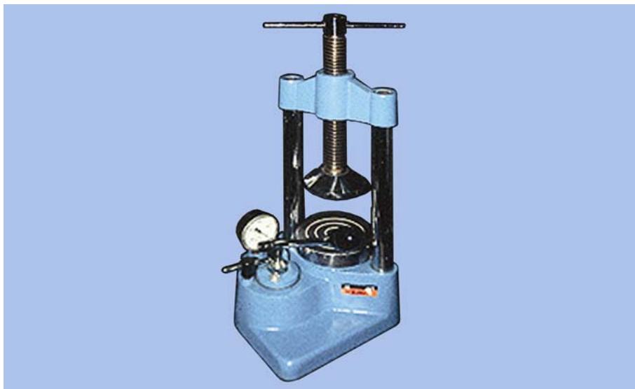
Figure 9.43. Pneumatic Flask Press.
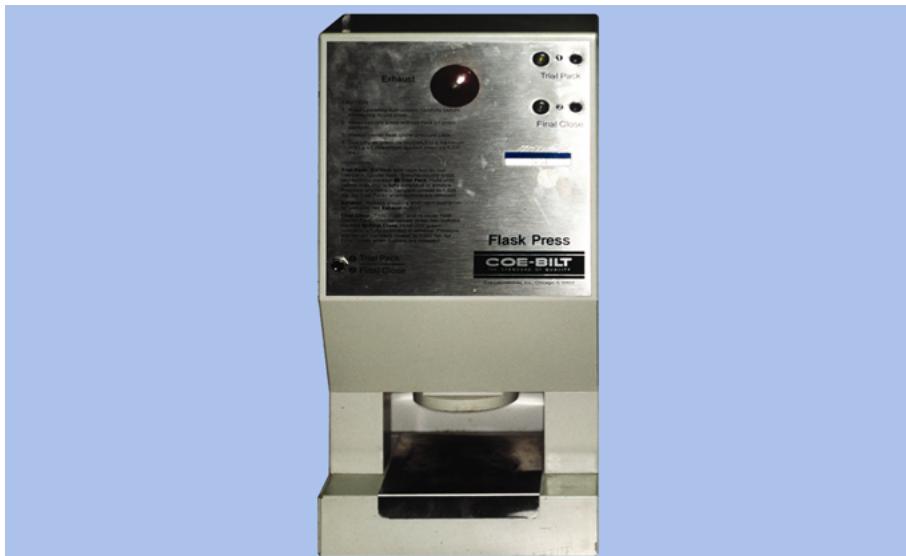
9.38.2. Maintenance. Only general cleaning is required.
9.38.3. Safety Considerations. Never operate the press without a flask. Always center the flask under the press. Use only air pressure regulated to manufacturer’s recommendations.
¶ 9.39. Biostar® Pressure-Moulding Machine
9.39.1. Purpose. This machine (Figure 9.45) is used to adapt round or square acrylic resin blanks onto casts by downward pressure from a pressure chamber located above the cast. Interim partial dentures, mouthguards, and orthodontic appliances can be processed with this machine.
9.39.2. Maintenance. Clean or replace block out pellets as needed. Do not exceed the optimal working pressure of 5 bars. Ensure the seal area between the pressure chamber and the ring on the working platform remains clean for proper seal during pressurizing. Clean the exterior of the machine regularly.
Figure 9.44. Ivocap® Pneumatic Press.
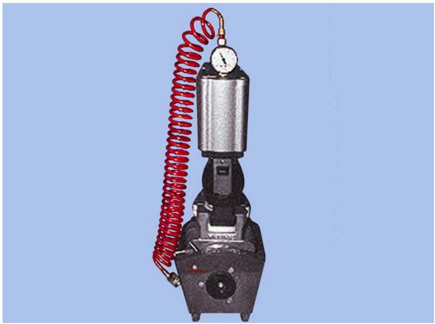
Figure 9.45. Biostar® Pressure-Moulding Machine.
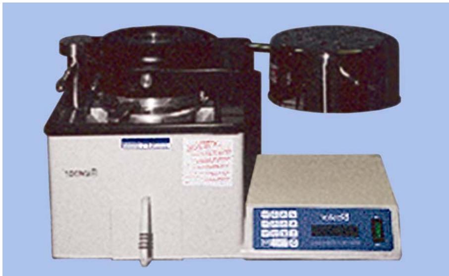
9.39.3. Safety Considerations. Wear safety glasses while operating the machine. Always use the handle when moving the heating element. Check the power cord periodically for fraying or other damage.
¶ 9.40. Vacuum Pump
9.40.1. Purpose. The vacuum pump (Figure 9.46) and similar other pumps are used to evacuate air from the firing chamber of porcelain firing furnaces. Vacuum pressure achieved is normally measured in inches of mercury.
Figure 9.46. Vacuum Pump.
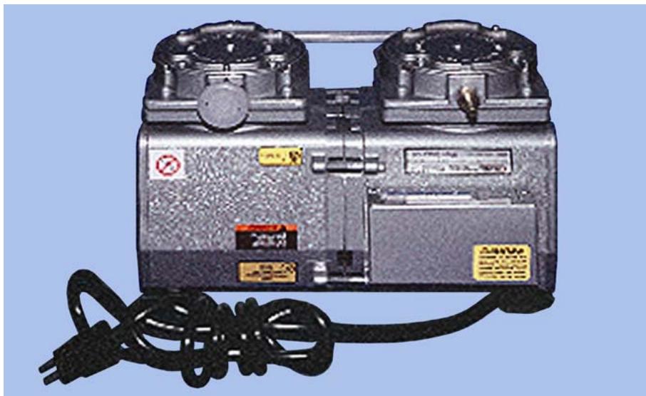
9.40.2. Maintenance. Read the manufacturer’s recommendations for maintenance on each type of pump. Most pumps require the intake and exhaust filters to be periodically checked and cleaned. If applicable, the oil in the vacuum pump should be replaced every 90 days or any time a change in color is noted in the inspection eye.
9.40.3. Safety Considerations. When performing maintenance on the pump, disconnect the power cord and vent all air lines to avoid personnel injury.
¶ 9.41. Laboratory Electronic Scale
9.41.1. Purpose. This scale (Figure 9.47) is used to weigh wax patterns to estimate the amount of metal required for casting. It can also be used to weigh dental stone and investments in the laboratory.
Figure 9.47. Laboratory Electronic Scale.
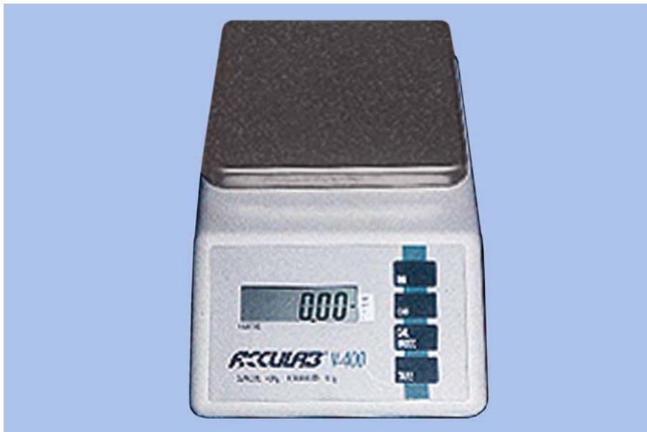
9.41.2. Maintenance. Keep the housing and pan free of dust and debris to ensure accurate weighing. Avoid rough treatment to the scale because it can damage the internal sensor. Because lengthy exposure to extreme heat or cold can affect its accuracy, the scale should be operated at room temperature. Calibration is preset at the factory. If recalibration is necessary, return it to an authorized service center.
¶ 9.42. Precious Metal Balance Scale
9.42.1. Purpose. This scale (Figure 9.48) is used for weighing precious metals in the laboratory. The scale readout is in grams.
Figure 9.48. Precious Metal Balance Scale.

9.42.2. Maintenance. The instrument must be cleaned after each weighing and covered with a dust protector when not in use. The precision measurement evaluation laboratory (PMEL) may periodically evaluate the accuracy of the scale.
¶ 9.43. Electric Soldering Unit
9.43.1. Purpose. The electric soldering unit (Figure 9.49) is used to solder RPD frameworks.
9.43.2. Maintenance. Keep the unit clean. Replace the carbon holders and carbon and ground prongs when they are no longer fit for use. Ensure electrical connections are kept clean.
9.43.3. Safety Considerations. Check the power line and plug before use. Wear safety glasses when soldering.
¶ 9.44. Hydroflame® Soldering Unit
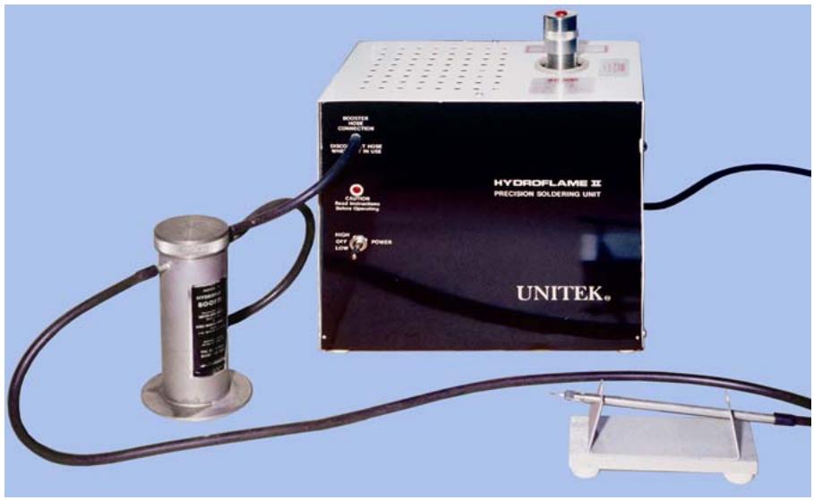
9.44.1. Purpose. The Hydroflame® soldering unit (Figure 9.50) converts water into hydrogen and oxygen to the correct proportion for ideal combustion. An alcohol booster unit is also used in the unit’s operation to lower the flame temperature to a more practical point. The hydroflame soldering unit is particularly suited for delicate soldering operations.
Figure 9.49. Electric Soldering Unit.
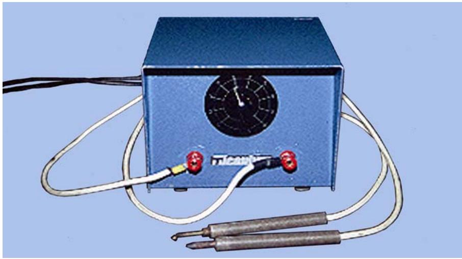
Figure 9.50. Hydroflame® Soldering Unit.
9.44.2. Maintenance.
9.44.2.1. Before each day’s use, run the cleaning wire through the torch tip. Check the generator electrolyte and booster fluid levels daily. Replenish fluid levels as necessary. When replacing the friction-fit torch tops, insert the tip with a pushing and twisting motion until it is tightly held on the torch handle.
9.44.2.2. Thoroughly clean and dry (or change) the stainless steel filter assembly every 3 months or 250 operating hours. Disconnect the booster hose from the gas generator outlet after extinguishing the flame and turn off the unit. (If it is not disconnected within 5 minutes, a vacuum will be created. The vacuum will then draw the booster fluid back into the generator and contaminate the electrolyte.)
9.44.2.3. Replace the electrolyte when it becomes contaminated or before 1,500 operating hours have elapsed. When you switch from “low” to “high,” pause momentarily at the center “off” position to avoid overloading the fuse.
9.44.3. Safety Considerations. Unplug the power cord from the wall outlet when you are not using the unit, and before you check the electrolyte and booster fluid levels. Avoid skin contact with the electrolyte fluid because it is extremely caustic. Do not place your face, particularly your eyes, close to or over an open filler tube or booster. Never allow an open flame, lit cigarette, or other hot, glowing material near the open mouth of the filler tube or booster because hydrogen and oxygen gases remain inside the generator for an hour after the electricity has been turned off. Wear safety glasses when you solder.
¶ 9.45. Steam Cleaner
9.45.1. Purpose. The steam cleaner (Figure 9.51) is used to clean using pressurized steam. It can be used on metal-ceramic frameworks and full gold crowns and to remove wax and debris from casts.
Figure 9.51. Steam Cleaner.
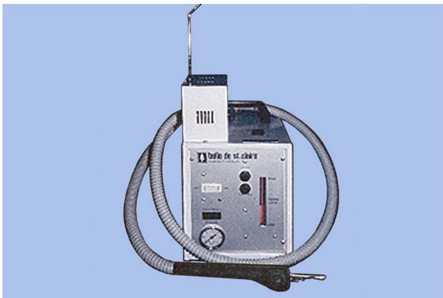
9.45.2. Maintenance. Drain the steam under pressure at the end of each workday. Once a month, turn the steamer off, disconnect the power cord from the electrical outlet, and check all internal electrical connections for tightness.
9.45.3. Safety Considerations. Always keep the steam nozzle pointed in a safe direction. Do not allow the water level to fall below the lower red line on the gauge glass because a reduced water level ultimately causes premature element failure.
¶ 9.46. Boilout Tanks
9.46.1. Purpose. Boilout tanks (Figure 9.52) are used primarily to soften and remove wax from invested denture flasks. Tanks can also be used to clean instruments and other metal objects.
9.46.2. Maintenance. Be sure the standpipe is in place before the pump is operated to eliminate stone and debris from being drawn through the pump. Allow the tank to cool and excess wax to be removed before draining and cleaning. Lubrication of the three oil cups on the pump is necessary every 4 months. Use 2 to 3 teaspoons in the front cup (for pump bearings) and 10 to 12 drops in each of the rear cups on motor. Always have at least 5 inches of water in the tank before igniting the burners. If the tank is equipped with a wax or plaster trap, clean it at least monthly.
Figure 9.52. Boilout Tanks.
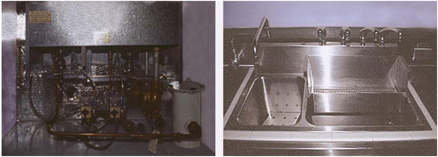
9.46.3. Safety Considerations. Always wear safety glasses and heat resistant gloves when operating the tank. If, during the lighting procedure, the pilot will not stay lit after several tries, turn the gas completely off and call a service technician. Stand clear of the facets when the pump is turned on to avoid being burned by splashing hot water.
¶ 9.47. Gas and Air Casting Torch (Multiorifice Blowpipe)
9.47.1. Purpose. This torch (Figure 9.53) is used primarily to melt and solder metals and alloys. The gas to air ratio is easily adjusted to provide the required heat intensity. Figure 9.53 shows the blowpipe with a casting tip attached. A smaller tip is used during soldering procedures to provide a smaller, more concentrated flame.
Figure 9.53. Gas and Air Casting Torch.
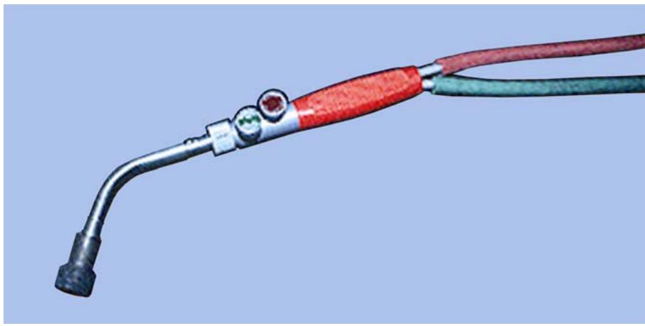
9.47.2. Maintenance. Periodically inspect the adjustment knobs of the torch for gas and air leaks. Check the casting or soldering tip before using it to ensure it is not clogged with dirt and debris.
9.47.3. Safety Considerations. Use noncollapsible-type hoses for the gas and air connections. Inspect the hoses for defects before each use. Never leave the torch unattended while lit.
¶ 9.48. Alcohol Torch
9.48.1. Purpose. This hand-operated torch (Figure 9.54) is ideal for setting up teeth, waxing, light soldering, and a variety of uses demanding accurate control of a pointed flame.
Figure 9.54. Alcohol Torch.
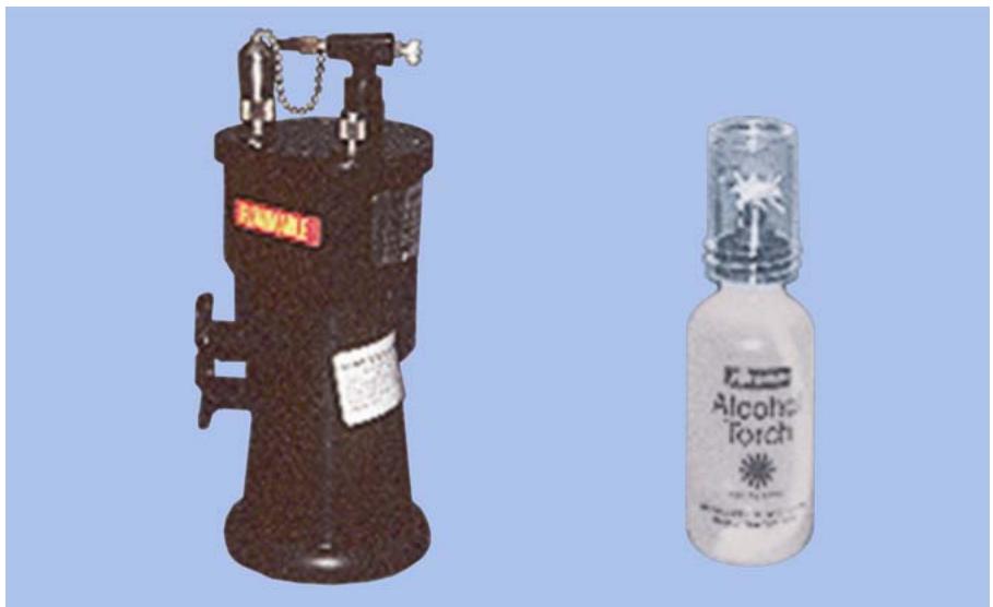
9.48.2. Maintenance. Check the nozzle tip to ensure it is free of obstructions. Replace the bellows diaphragm as needed. Clean the exterior of the pump daily to prevent accumulation of waxes and compounds.
9.48.3. Safety Considerations. Extinguish the torch when it is not in use by covering the wick with the attached wick shield. Do not leave the torch unattended while lit.
¶ 9.49. Cast Trimmer
9.49.1. Purpose. The cast trimmer (Figure 9.55) is used to trim and contour the casts to a workable size.
Figure 9.55. Cast Trimmer.
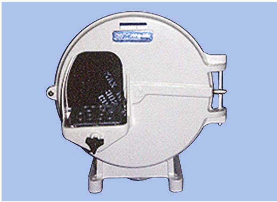
9.49.2. Maintenance. If applicable, lubricate the wheel shaft by placing two drops of medium grade oil in each of the two exposed oil cups every 2 weeks. Use sufficient water to prevent clogging the trimmer wheel with gypsum grindings. Let the water run at least 1 minute after the grinding is complete to flush all particles out of the drain. Clean the trimmer at least monthly or more frequently, depending on the amount of usage. Do not allow the trap or drain to become clogged before cleaning it. Check connecting hoses for water leaks. Apply only light pressure while trimming the cast. If the wheel does not cut, follow the manufacturer’s directions to replace it. If the unit does not run smoothly, call the medical equipment repair personnel.
9.49.3. Safety Considerations. Wear safety glasses when operating the cast trimmer. Check the cord for wear or damage. Keep your fingers away from the wheel.
¶ 9.50. Ticonium® Twin Controller
9.50.1. Purpose. The twin controller (Figure 9.56) is an electronic device that automatically operates the Ticonium Super Oven or a vertical loading oven. When properly adjusted, it activates an oven, maintains a predetermined maximum burnout temperature for specific time periods, and deactivates the oven after the programmed burnout time elapses.
Figure 9.56. Ticonium® Twin Controller.
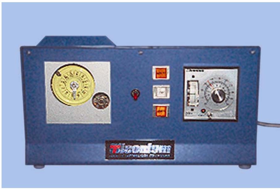
9.50.2. Maintenance. Do not subject the instrument to excessive shock, vibration, dust, moisture, or oil seepage. Make sure the ambient temperature where the controller is located does not exceed 130 °F.
9.50.3. Safety Considerations. Inspect the power line and plug daily for defects.
¶ 9.51. Vacuum Former
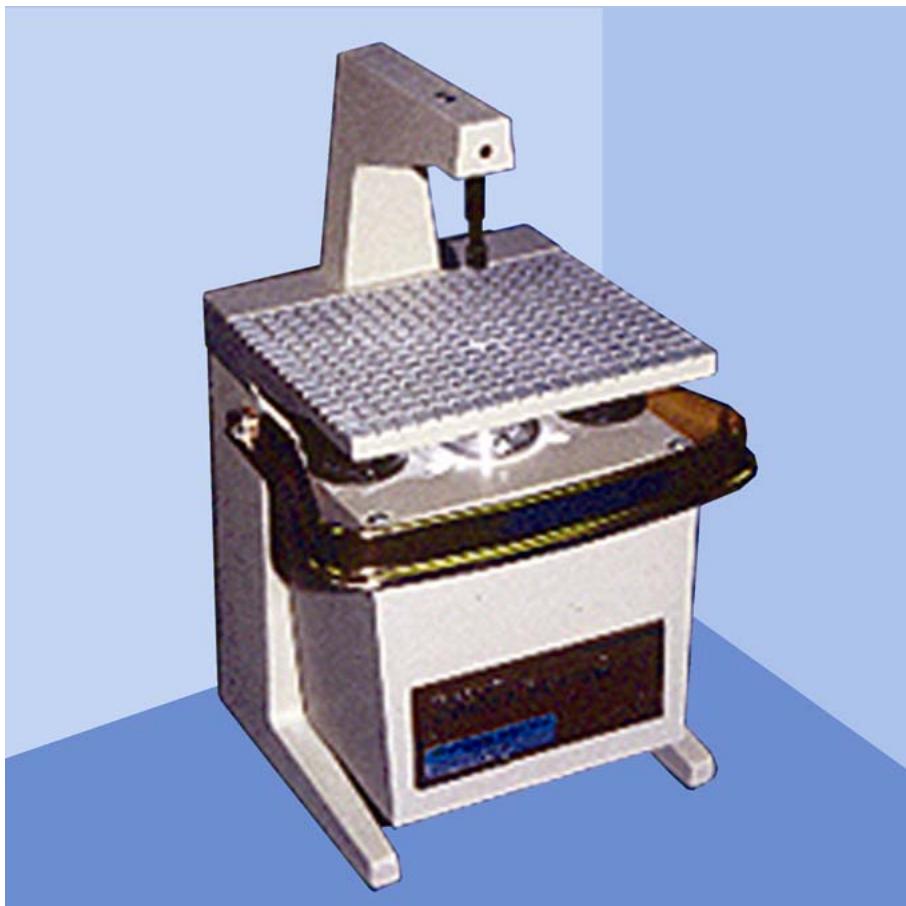
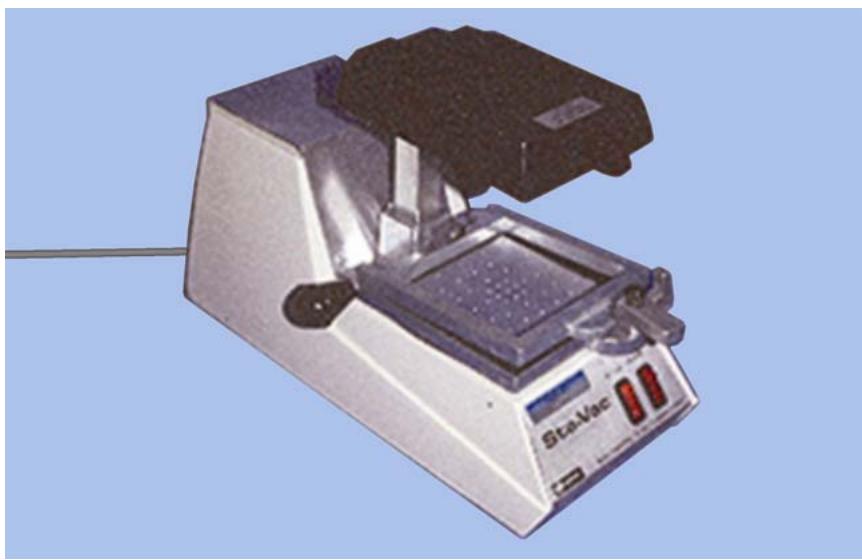
9.51.1. Purpose. This unit is a vacuum adapter of sheet plastic (Figure 9.57). It is used for rapid fabrication of record bases, custom impression trays, surgical bases, mouth guards, night guards, and temporary FPDs.
9.51.2. Maintenance. Inspect the rubber sealing gasket for cracks and deterioration and replace as necessary. Inspect the vacuum holes in the platform to ensure they are free of obstruction. Clean the exterior of the unit.
9.51.3. Safety Consideration. Inspect the electrical cord and plug daily for defects. Use the handle of the machine to raise and lower the heating coil.
Figure 9.57. Vacuum Former.
¶ 9.52. Vibrator
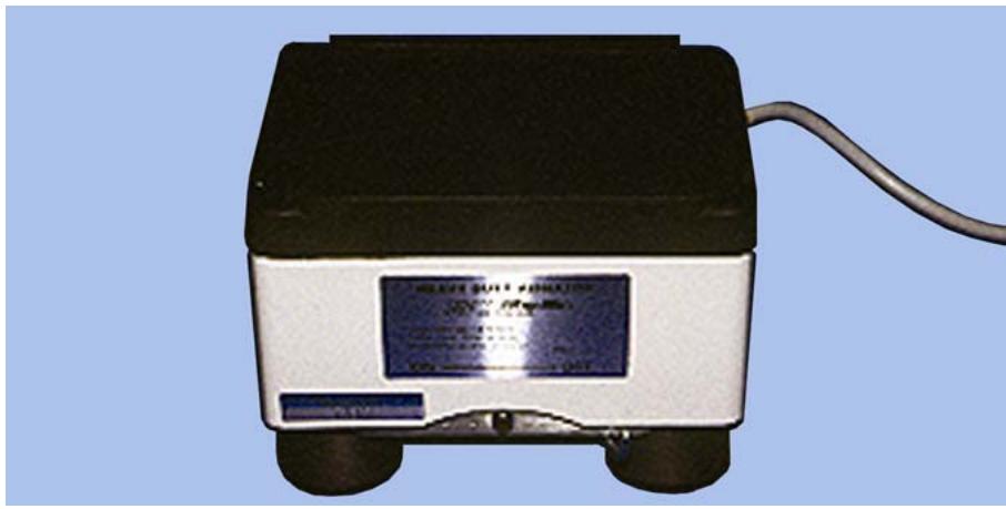
9.52.1. Purpose. The vibrator (Figure 9.58) is used to get a mix of a gypsum product to move when you pour impressions and perform various investing procedures. It is also used to increase the density of the mix by eliminating air through vibration. A rheostat control is used to adjust the intensity of the vibration from a gentle agitation to a vigorous shaking. The intensity of the vibration is directly proportional to the viscosity of the mix.
Figure 9.58. Vibrator.
9.52.2. Maintenance. General cleaning of the pouring platform and body of the vibrator should be done every day.
9.52.3. Safety Considerations. Check the power line and plug for defects before each use. Always turn the unit to the lowest setting on the rheostat after each use.
¶ 9.53. Electric Waxing Unit
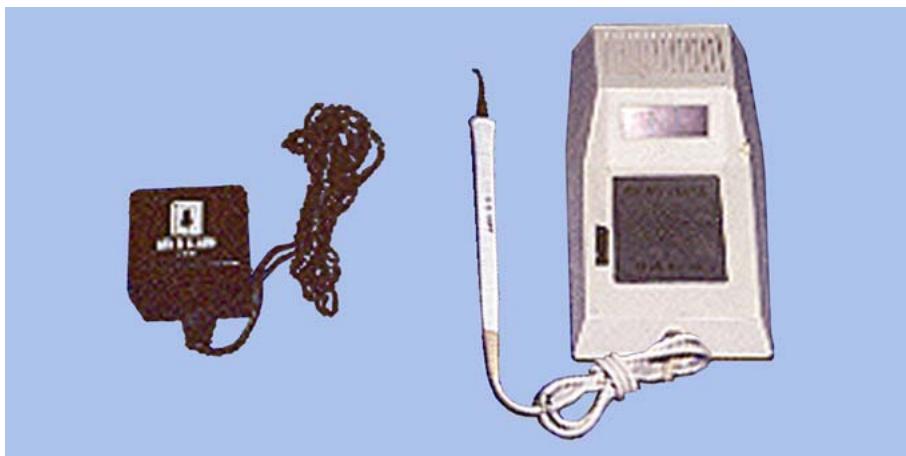
9.53.1. Purpose. This unit (Figure 9.59) is a precision electronic waxing instrument. It has several different waxing tips that correspond to the conventional hand instruments used for waxing and carving. The temperature of the tip can be controlled to suit the operator’s needs.
Figure 9.59. Electric Waxing Unit.
9.53.2. Maintenance. Never cover the top vent holes. Do not allow wax or debris to enter the unit through the vent holes. Only a qualified technician should open the unit for any repairs. Do not set the temperature higher than necessary. Do not use the standard waxing tip holder above 450 °F. Keep the spatula tips clean and free of carbonized wax.
9.53.3. Safety Considerations. Turn the unit off when it is not in use. Do not mount the spatula stand on the waxing unit.
Surgeon
GEORGE P. TAYLOR, JR., Lt Gen, USAF, MC, CFS General
DentalTechnology.org is dedicated to preserving, teaching, and advancing the craft of dental technology.
This resource is made possible by Russellville Dental Lab, a full-service dental laboratory in Russellville, Kentucky, serving clinicians across the USA for more than 70 years.